1
SeeGull® MX
SeeGull® MX Scanning Receiver
Hardware Reference Manual
Document Number: 100070-00
Revision F
June 2012
SeeGull® MX Hardware Reference Manual
COMMENT ON DEFECTS AND OTHER ERRATA
PCTEL is committed to releasing defect free products, and appreciates any reports of issues or
assistance in the identification of issues. Problems are prioritized and queued for remedy.
PCTEL is always interested in your feedback concerning our products, and the features or
additions that would make them better. Please feel free to contact PCTEL using the support
information below with any suggestions for improvements.
Trademarks
®
®
®
© 2012 PCTEL, Inc. All rights reserved. PCTEL, SeeGull , SeeHawk , CLARIFY , the
®
CLARIFY and PCTEL logos are trademarks of PCTEL, Inc. All other trademarks are property
of their respective owners.
Notices and Warranty Information
The information in this document is subject to change without notice and should not be
construed as a commitment by PCTEL. PCTEL assumes no responsibility and makes no
warranties for any errors that may appear in this document and disclaims any implied warranty
of merchantability or fitness for a particular purpose.
Copyright Information
No part of this document may be used or copied in any form or any means without prior written
consent of PCTEL.
All Rights Reserved
Copyright 1997-2012
PCTEL, Inc.
RF Solutions
20410 Observation Drive, Suite 200
Germantown, MD 20876 USA
Phone: +1 301 515 0036
Fax: +1 301 515 0037
PCTEL, Inc.
Page ii
Rev. F
SeeGull® MX Hardware Reference Manual
Table of Contents
1. 1.1. 1.2. 1.3. 1.4. 2. 2.1. 2.2. 2.3. 3. 3.1. 3.2. 4. 4.1. 4.2. 4.3. 5. 5.1. 5.2. 5.3. 6. 6.1. 6.2. 7. 7.1. 7.2. 8. 8.1. 8.2. 8.3. 8.4. 9. 9.1. 9.2. Preface ............................................................................................................................................................ 1 Purpose ............................................................................................................................................................ 1 Applicability .................................................................................................................................................... 1 Compliance ..................................................................................................................................................... 2 Copyrights and Restrictions ............................................................................................................................ 3 Overview and System Requirements ........................................................................................................... 4 General Description......................................................................................................................................... 4 Measurement Options ..................................................................................................................................... 4 System Requirements ...................................................................................................................................... 6 Installation ..................................................................................................................................................... 8 Integration ....................................................................................................................................................... 8 Setup................................................................................................................................................................ 8 Operation ..................................................................................................................................................... 11 Calibration ..................................................................................................................................................... 11 Software Upgrades ........................................................................................................................................ 11 Controlling the Scanner and Acquiring Data ................................................................................................ 11 RF Antenna Information ............................................................................................................................ 12 Antenna Verification ..................................................................................................................................... 12 Cellular Antennas .......................................................................................................................................... 12 GPS Antenna Information ............................................................................................................................. 13 Indoor Kit Information ............................................................................................................................... 14 Indoor Kits .................................................................................................................................................... 14 RF Indoor Antenna Information .................................................................................................................... 14 Troubleshooting ........................................................................................................................................... 15 No Power: Receiver LED not Illuminated .................................................................................................... 15 Received Signal Strength Appears Low ........................................................................................................ 15 Support ......................................................................................................................................................... 16 Contact Information ...................................................................................................................................... 16 Warranty Information .................................................................................................................................... 16 Calibration Notice ......................................................................................................................................... 17 Return Material Authorization Procedure for the SeeGull MX Scanning Receivers .................................... 17 Accessories and Service Options ................................................................................................................ 18 Accessories .................................................................................................................................................... 18 Service Options ............................................................................................................................................. 18 PCTEL, Inc.
Page iii
Rev. F
SeeGull® MX Hardware Reference Manual
List of Figures
Figure 1. SeeGull MX Scanning Receiver ..................................................................................................................... 4 Figure 2. Display from SeeHawk, SeeGull’s Optional Drive Test Software Suite ........................................................ 7 Figure 3. SeeGull MX Scanning Receiver Bottom View ................................................................................................ 8 Figure 4. SeeGull MX Scanning Receiver Air Intake (Right Side View) ....................................................................... 8 Figure 5. SeeGull MX Scanning Receiver Air Exhaust (Left Side View) ....................................................................... 8 Figure 6. Label Identifying Antenna Locations ............................................................................................................. 9 Figure 7. Connections and Switches for SeeGull MX.................................................................................................. 10 Figure 8. Connections and Switches for SeeGull MX Setup with 4 MIMO ports ........................................................ 10 Figure 9. OP078H & OP216 ....................................................................................................................................... 12 Figure 10. OP079H & OP217H .................................................................................................................................. 13 Figure 11. OP034H ..................................................................................................................................................... 13 Figure 12. MX Indoor Kit ............................................................................................................................................ 14 Figure 13. SeeGull MX Scanning Receiver Power ...................................................................................................... 15 List of Tables
Table 1: Phone Numbers ............................................................................................................................................. 16 Table 2: Email Addresses ............................................................................................................................................ 16 Table 3: SeeGull MX Cables and Connectors ............................................................................................................. 18 Table 4: SeeGull MX Antennas.................................................................................................................................... 18 Table 5: SeeGull MX Indoor Kit Accessories .............................................................................................................. 18 Table 6: SeeGull MX Calibration Service ................................................................................................................... 18 Table 7: SeeGull MX Repair Service ........................................................................................................................... 19 Table 8: SeeGull MX Warranty Options...................................................................................................................... 19 PCTEL, Inc.
Page iv
Rev. F
SeeGull® MX Hardware Reference Manual
1. Preface
1.1.
Purpose
This document is a user’s manual for the
SeeGull MX Scanning Receiver. It
describes the main features and options
available for the SeeGull MX and provides
instructions related to setup, operation, and
maintenance of the scanners. This
document may be supplemented by other
documentation for the SeeGull MX or
related PCTEL products and applications.
1.2.
The following bands are supported for TDLTE:
E-UTRA 38 (IMT Extension 2.5G)
E-UTRA 39 (1.8 TDD)
E-UTRA 40 (2.3 TDD)
E-UTRA L41 (Lower 41 2.5G)
Applicability
The SeeGull MX Scanning Receiver
conducts drive test and site-specific
measurements of mobile networks around
the world to optimize wireless network
performance, survey tower sites, monitor
base stations, demodulate RF signals and
analyze wireless market data.
The SeeGull MX Scanning Receiver is a
software-defined receiver, capable of
supporting multiple protocols and up to 8
frequency ranges. It can be configured for
TD-LTE, LTE-FDD, WCDMA, CDMA, EVDO and GSM technologies. The following
bands are supported for LTE-FDD with a
subset of these bands supported for
WCDMA, CDMA, EV-DO and GSM:
E-UTRA 25 (1990 MHz [Ext. 1900])
E-UTRA 4 (2100 MHz AWS)
E-UTRA 1 (2100 MHz UMTS)
E-UTRA 7 (2600 MHz IMT)
E-UTRA 12 (Lower 700 MHz A/B/C)
E-UTRA 17 (Lower 700 MHz B/C)
E-UTRA 13 (Upper 700 MHz C)
E-UTRA 18 (Lower 800 MHz Japan)
E-UTRA 19 (Upper 800 MHz Japan)
E-UTRA 20 (800 MHz EU)
E-UTRA 5 (850 MHz)
E-UTRA 26 (Upper Ext 850 MHz)
E-UTRA 27 (Lower Ext 850 MHz)
E-UTRA 8 (900 MHz UMTS)
E-UTRA 11 (1500 MHz Japan)
E-UTRA 21 (1510 MHz Japan)
E-UTRA 9 (1700 MHz Japan)
E-UTRA 3 (1800 MHz)
E-UTRA 2 (1900 MHz)
PCTEL, Inc.
For more information about the SeeGull MX,
please contact your sales or marketing
representative (contact information provided
in Section 8.1).
Features
Fast scanning speeds
High dynamic range
Low false detection rate
Scans multiple bands without
performance degradation
Concurrent measurements in:
o LTE/WCDMA/GSM
o LTE/CDMA/EV-DO
Built-in GPS
LTE Measurement Averaging
Outdoor and Indoor Modes
USB Interface
Plug-and-play capabilities
Compatibility with industry-leading
drive test, data analysis, and RF
planning tools
Modular architecture for easy
upgrades
Ignition sense
Sleek, durable design
Page 1
Revision F
SeeGull® MX Hardware Reference Manual
Supported Measurements
LTE (FDD and TDD)
Top N and Top N Reference Signal
Scan
P-SCH/S-SCH
RSRP, RSRQ
CINR
Cyclic Prefix
Time Offset
Multi-Path Delay Spread
Averaging Modes
TD-LTE Specific
Uplink/Downlink Configuration #
DwPTS Symbol
GSM
BSIC Decoding Scan
RSSI Channel Scan
C/I (Co-Channel Interference)
WCDMA
Top N Scan
P-SCH/S-SCH Scan
Ec
Ec/Io and Aggregate Ec/Io
Signal to Interference Ratio (SIR)
Rake Finger Count
RSSI Channel Scan
CDMA
Top N Scan
Ec
Ec/Io and Aggregate Ec/Io
Pilot Delay and Delay
RSSI Channel Scan
EV-DO
Top N Scan
Ec
Ec/Io and Aggregate Ec/Io
Pilot Delay and Delay
RSSI Channel Scan
MULTI-TECHNOLOGY
Aggregate Power Measurement
(RSSI, EPS or Spectrum Analysis)
PCTEL, Inc.
Delay and Signal Strength of
neighboring cells
Peak Preamble Power measurement
RSSI Channel Scans
Spectrum Analyzer Measurements
High Performance GPS Receiver
For more information please visit
www.pctel.com.
WARNING: These devices have no
protection against lightning. Please turn off
the scanning receiver during a thunderstorm
and, if applicable, take antennas inside the
vehicle before a thunderstorm approaches.
The scanning receiver itself is not intended
for “in weather” outdoor use.
NOTICE: There are no user serviceable
parts inside the SeeGull MX Scanning
Receivers.
1.3.
Compliance
CE Safety Compliance
PCTEL SeeGull MX Scanning Receivers
are compliant to EN 60950 Information
Technology Equipment-Safety- Part 1:
General Requirements.
EMC Compliance
PCTEL SeeGull MX Scanning Receivers
are compliant to EN 301 489-1
Electromagnetic compatibility
and Radio spectrum Matters (ERM);
ElectroMagnetic Compatibility (EMC)
standard for radio equipment and services;
Part 1: Common Technical Requirements.
RoHS Compliance
Page 2
Revision F
SeeGull® MX Hardware Reference Manual
PCTEL SeeGull MX Scanning Receivers
delivered to participating European nations
are compliant to EU Directive 2002/95/EC
(RoHS).
PCTEL SeeGull MX Scanning Receivers
are compliant to "Administrative Measure on
the Control of Pollution Caused by
Electronic Information Products" ("China
RoHS").
ISO Compliance
RF Solutions Quality Management System
has been certified to be compliant with ISO
9001:2008.
Restrictions
This document contains proprietary
information that is protected by copyright; it
is intended for use by PCTEL customers
only and is not to be disclosed to any third
party. All rights reserved. No part of this
document may be photocopied or
reproduced in any way without the prior
written permission of PCTEL, Inc. The
information contained in this document is
subject to change without notice. PCTEL,
Inc. makes no warranty of any kind with
regards to this document. PCTEL, Inc. shall
not be liable for errors or omissions
contained herein or for incidental or
consequential damages in connection with
the use of this document.
Trademarks
© 2012 PCTEL, Inc. All rights reserved.
®
®
®
PCTEL, SeeGull , SeeHawk , CLARIFY ,
®
the CLARIFY logo and the PCTEL logo are
trademarks of PCTEL, Inc. All other
trademarks are property of their respective
owners. Specifications are subject to
change without notice.
1.4.
Copyrights and Restrictions
Copyright Information
No part of this document may be used or
copied in any form or any means without
prior written consent of PCTEL.
All Rights Reserved
Copyright 2012
PCTEL, Inc.
RF Solutions
20410 Observation Drive
Suite 200
Germantown, MD 20876 USA
Phone: +1 (301) 515-0036
Fax: +1 (301) 515-0037
PCTEL, Inc.
Page 3
Revision F
SeeGull® MX Hardware Reference Manual
2. Overview and System
Requirements
This section describes the SeeGull MX
Scanning Receiver, including the applicable
system configuration and software
requirements.
2.1.
General Description
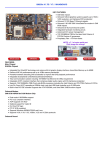
The SeeGull MX Scanning Receiver (Figure
1) is a tool for signal strength and
modulation measurement, engineered for
the rigors of mobile network testing during
planning, installation, and maintenance of
wireless networks. It supports
LTE/WCDMA/GSM or LTE/CDMA/EV-DO
protocols with either 4 or 8 band-designated
receive antenna (RX) ports.
contents are incomplete or the SeeGull MX
Scanning Receiver appears damaged,
please call the Technical Support line at
(240) 460-8833.
2.2.
Measurement Options
Optional multi-technology measurements
available for the SeeGull MX are described
below. These options can be installed at the
time of purchase or later on as a field
upgradeable option. Please contact your
PCTEL sales or marketing representative
for pricing and delivery information.
Enhanced Power Scan (EPSTM) Option
(OP514)
EPS Mode provides customizable power
measurements, improving flexibility and
precision over RSSI and Spectrum Analyzer
measurements for highly-tuned analysis of
individual parts of the RF signal. EPS
features include:
Figure 1. SeeGull MX Scanning Receiver
The USB communication link allows the
host to control the operation of the scanner
and to receive measurement results. (Refer
to Section 4 for more details).
Initial Inspection
Upon receipt of the scanning receiver,
inspect the shipping container and verify
that the contents are complete and match
the packing list. The receiver should look
similar to the picture in Figure 1. If the
PCTEL, Inc.
Absolute Time Stamp
Auto and Immediate Measurement
Modes
Ability to set both Time and Frequency
parameters
Measure Frequency Spans from 7.5 kHz
to 20 MHz user selectable in multiples of
2.5 kHz
Measures Time Periods from 1 chip (50
µs) to 20,000 chips (1sec)
Spectrum Analyzer Option (OP513)
The built-in Spectrum Analyzer feature
provides an effective means to detect and
troubleshoot frequency-related problems.
The Spectrum Analyzer shows a wealth of
information about the signal spectrum that is
not obtainable from the standard channel
power measurement.
Page 4
Revision F
SeeGull® MX Hardware Reference Manual
The Spectrum Analyzer measures and
reports power spectral density using
frequency domain techniques (a segmented
FFT approach that ensures various
resolution bandwidths and fast update
rates), whereas RSSI measurements use
analog and digital filters to select the right
frequency band and subsequently measure
total power.
One advantage of this approach is that the
Spectrum Analyzer can analyze the fastchanging spectrum of an unstable
transmitter. The RSSI measurement in this
case will most often show a normal smooth
picture, as it averages a limited set of data
over time. The Spectrum Analyzer,
however, if used with an appropriate
resolution bandwidth, will reveal erratic
signal behavior due to its fast update rate
and unaveraged data.
The user may set the resolution bandwidth
to 5, 10, 20, 40 or 80 kHz. Output data may
be set to an average of 1, 2, 4, 8, or 16
sweeps.
LTE Power Analysis (OP516)
LTE Power Analysis is available for TD-LTE
and provides power of the resource block
and slot of the TD-LTE frame. This enables
users to identify interference that is time
(slots) or frequency (RBs)-selective, to
obtain a snapshot of overall traffic levels,
and to determine whether base station is
properly using the available resources.
Layer 3 Options
(OP522 All Layer 3 Options)
(OP522-GSM)
(OP522-TD-LTE)
(OP522-WCDMA)
Layer 3 decoding is available for GSM, TDLTE, and WCDMA technologies. This
option, provides decoding for:
Blind Scan Options
(OP521 All Blind Scan Technologies)
(OP521-GSM)
(OP521-WCDMA)
(OP521-FD-LTE)
(OP521-TD-LTE)
Blind Scan is available for LTE-FDD, TDLTE, WCDMA and GSM technologies. This
feature scans the selected band and
provides the active channel numbers. Blind
Scan is useful for conducting a full band
network search where prior knowledge
about active channels is incomplete or
unknown. It is also beneficial for network
benchmarking to obtain a first-glance view
of the RF infrastructure density and
configuration.
PCTEL, Inc.
GSM BCCH (Broadcast Control
Channel) messages
WCDMA BCH (Broadcast Control
Channel) Type 3 messages
TD-BCH (Broadcast Control
Channel)
In the GSM BCCH, types 1, 2, 3, 4, 9, and
type 13 messages are supported. In the
WCDMA BCH, the Master Information Block
(MIB) and the System Information Blocks
(SIBs) 1, 2, 3, 5, 7, 11 and 19 are
supported. In the GSM BCCH and the
WCDMA BCH, these messages contain the
Cell Identity and Local Area Identification
information broadcast by the network
infrastructure. This information includes
the:
Page 5
MCC (Mobile Country Code),
MNC (Mobile Network Code),
LAC (Location Area Code)
RAC
Revision F
SeeGull® MX Hardware Reference Manual
These messages also contain significant
information on the configuration, activity and
performance of the network. This includes
information concerning:
Neighbor list
Mobility management (handovers,
etc.)
Group and broadcast call control
GPRS mobility management,
transparent transport and session
management
Radio resource management
SMS messages
Location services
Uplink Interference parameters
(WCDMA only).
TD-LTE BCH layer 3 messages convey
system information about the cell. These
messages contain the cell identity, channel
bandwidth, mobility management
(handovers), neighbor lists, barred cells,
intra-frequency selection, public safety
messages, etc. It supports decoding of the
MIB and SIBs 1-13.
The SeeGull MX supports scanning of
numerous GSM BCCH and WCDMA/TDLTE BCCH channels during the same test.
2.3.
System Requirements
This section describes the system
requirements for the SeeGull MX Scanning
Receiver.
Typical System
Various hardware and software components
may be used in the scanning system along
with the SeeGull MX Scanning Receiver.
However, a typical configuration will include
a host PC running the user’s application
software with a USB cable connection to the
scanner.
PCTEL, Inc.
Antenna Requirements
Use a 50 Ohm impedance antenna with an
SMA male connector at the end of the
cable. Refer to PCTEL’s product offering
matrix in Section 9 for part number
information.
Note: Outdoor antennas, including those
used by other devices, should be placed a
minimum of 6 in. (15 cm) apart, with a
recommended distance of 34 in. (86 cm).
Refer to the Instructional Guide: SeeGull
Antennas for MIMO and MISO Antenna
Schemes for further details.
Power Source Requirements
The SeeGull MX Scanning Receiver uses 8
to 16 VDC using the cigarette lighter cable
and 10 to 16 VDC for the 12 foot
battery/fuse box cable (measured at the
battery connector) and draws 6.0 amps
(nominal) @ 12 VDC. The maximum current
rating is 10 amps. The scanner can be
powered by a vehicle battery, a 12-volt
battery, or an AC/DC adapter. The power
source must be capable of supplying the
receiver with the voltage and current levels
as above. PCTEL HIGHLY recommends
that the power supply voltage not exceed
the working range of the SeeGull MX
Scanning Receiver. Applying excessive
voltage to the receiver will void the unit’s
warranty.
The scanning receiver must be powered
through the power cable provided by
PCTEL. The power cable is equipped with
an additional tab to sense the voltage drain
of the vehicle’s battery or if the vehicle’s
ignition is turned off. This feature is called
Ignition Sense Feature and is very useful
to prevent the vehicle’s battery from
discharging if the scanner is left on when
the vehicle is turned off. In order to prevent
the scanner from draining the vehicle’s
battery, the ignition sense wire turns off the
Page 6
Revision F
SeeGull® MX Hardware Reference Manual
scanner when it senses the vehicle ignition
has been off for 30 minutes or the available
power drops below the usable voltage. The
wire connects to any fuse socket on the
vehicle that has power when the vehicle’s
ignition is turned on.
Use of another power cord will void any
warranties and may result in an unsafe
condition. Refer to Section 7.1 for further
details on power cord troubleshooting.
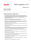
Software Requirements
Option 1:
SeeHawk
PCTEL’s SeeHawk (Figure 2), a data
collection software package, allows for
control of PCTEL’s receivers and data
acquisition without the need for users to
develop their own software. Contact your
PCTEL sales representative for more
information.
Option 2:
Windows Based Control
For users planning to develop proprietary
software to control the SeeGull MX
Scanning Receiver using the Windows OS,
PCTEL can provide the SeeGull MX
Scanning Receiver Applications
Programmers Interface (API) and Reference
or ASN.1 Reference documents.
Figure 2. Display from SeeHawk, SeeGull’s Optional Drive Test Software Suite
PCTEL, Inc.
Page 7
Revision F
SeeGull® MX Hardware Reference Manual
3.
Installation
This section describes how to set up the
SeeGull MX Scanning Receiver.
3.1.
Integration
There are four (4) mounting holes (4-40
screw) on the chassis of the unit that are used
for mounting in the user’s enclosure/rack.
Avoid obstructing airways when mounting this
unit in a system enclosure, rack, or case.
Unobstructed convection airflow is
recommended.
7.850”
1.000”
5.625”
0.252”
Figure 5. SeeGull MX Scanning Receiver Air
Exhaust (Left Side View)
3.2.
Setup
Follow the steps below to connect the unit
to the host PC and power source before
collecting data. See Figure 7 for the
locations of connections and switches on
the front of the SeeGull MX.
Front
4.344”
5.406”
Rear
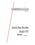
1. Connect the antennas to the SMA
RF connectors on the unit. The
antenna ports RF1 to RF4 (or RF1
to RF6 or RF8 for MIMO-enabled
units) on the label (in Figure 6)
show the frequencies supported
on each RF port. The frequency
range of the antenna must include
the frequency band of the RF port
to which it is connected. For
example, the “RF4” box on the
label in Figure 6 lists 850 and L
700 ABC bands (where “L” stands
for Lower). Therefore, connect
PCTEL’s 698-2300 MHz low band
antenna to this port (for outdoor
use).
Figure 3. SeeGull MX Scanning Receiver Bottom
View
Note: Do not obstruct air intakes or exhaust
on unit. Do not place the unit intakes next to
the exhaust of another heat source.
Airway intakes are located on the right, and
airway exhaust is located on the left, as
shown in Figure 4 and Figure 5.
Note: Refer to the Instructional
Guide: SeeGull Antennas for MIMO
and MISO Antenna Schemes for
further detail on connecting the
proper antenna type to the correct
antenna port.
Figure 4. SeeGull MX Scanning Receiver Air Intake
(Right Side View)
PCTEL, Inc.
Page 8
Revision F
SeeGull® MX Hardware Reference Manual
The scanner will operate normally
whether or not the ignition sense
wire is used.
6. Turn the SeeGull MX scanner on
by moving the Indoor/Outdoor
switch (5) from the OFF position to
the INDOOR or ON position. ON
mode is used for normal outdoor
operation. INDOOR mode reduces
the fan noise emanating from the
scanner for indoor operation.
Future plans include reducing
power consumption for indoor
mode.
Figure 6. Label Identifying Antenna Locations
2. Connect the GPS antenna (or input) to
the GPS SMA connector (4). An SMA
to SMB adapter is shipped in a bag
labeled OP225 with the SeeGull MX to
allow the OP034H SMB connector on
the GPS antenna to mate with the
SeeGull MX GPS port.
Note: The GPS LED colors indicate
the following states:
Green: GPS module locked to GPS
signal
Amber: GPS module unlocked
Flashing Amber: Lost GPS lock
within past 5 seconds
Red: System Error
Purple: GPS not trained (may take
up to 20 minutes and will only
occur after a software upgrade
from early software versions)
3. Connect the USB data connector (2)
to a PC USB port with the USB cable.
4. Connect the power cable to the
scanner’s power connector (6) and to
the vehicle’s cigarette lighter adapter.
Make sure to line up the red dots on
the cable and the power connector.
5. Optionally, connect the ignition sense
wire, a wire on the power cable which
can be used to sense power to your
ignition. Refer Section 2.3 for further
details of the ignitions sense feature.
PCTEL, Inc.
Page 9
Revision F
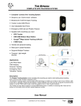
SeeGull® MX Hardware Reference Manual
1. SMA
Connectors to
RF antennas
2. USB data
connector
3. Status
Indicator
7. During power-up, the status LED
(3) is amber for up to several
minutes. After initialization is
complete the status LED turns
green. If the LED turns dark red,
the unit has failed the power-up
test. Please contact Technical
Support.
8. Install and start your PC drive test
program. If you are using
SeeHawk, refer to the SeeHawk
User Manual for specific
instructions.
4. SMA Connector
to GPS antenna
(use SMA to SMB
adapter)
9. The system is ready for use.
Afterwards, please turn the
Indoor/Outdoor switch (5) to OFF
and disconnect all cables.
5. Indoor /
Outdoor switch
6. Power
connector
Figure 7. Connections and Switches for SeeGull MX
1. SMA
Connectors to
RF antennas
Figure 8. Connections and Switches for SeeGull MX
Setup with 8 MIMO ports
PCTEL, Inc.
Page 10
Revision F
SeeGull® MX Hardware Reference Manual
Windows XP, or Windows 7 use
PCTEL’s Application Programming
Interface (API).
4. Operation
This section discusses calibration, software
upgrades, and integration of the SeeGull MX
Scanning Receiver into the user’s test
system.
4.1.
Calibration
SeeGull MX Scanning Receivers are
calibrated at the factory. Recalibration is
recommended every two years in order to
maintain specified accuracy levels. The date
of the last calibration is listed on a label
attached to the SeeGull MX. Please refer to
the Calibration Notice in Section 8.3 for more
information. Re-calibration is available as an
optional service from PCTEL.
If the user has a system that runs on
an operating system other than
Windows, use the description of the
USB interface and messages found in
the SeeGull MX Product Reference.
Note: PCTEL recommends having the
SeeGull MX Scanning Receiver
recalibrated every 2 years.
4.2.
Software Upgrades
The SeeGull MX Scanning Receiver stores
the application program in internal, nonvolatile memory, enabling software-based
upgrades to the scanner. Upgrades may be
needed to incorporate new features or bug
fixes. Please note that some upgrades can
only be performed at PCTEL’s factory.
4.3.
Controlling the Scanner and
Acquiring Data
Once the SeeGull MX has been set up (see
Section 3), software such as PCTEL’s
SeeHawk may be used to control the scanner
and acquire data.
A unit is controlled and the measurement data
are received, via the USB communication link.
If the user incorporates the scanner into a
test system that runs on Windows Vista,
PCTEL, Inc.
Page 11
Revision F
SeeGull® MX Hardware Reference Manual
5.
RF Antenna Information
This section discusses antennas that are
used with the SeeGull Scanning Receiver
system.
5.1.
Antenna Verification
Verify that all the necessary antennas are
included in the shipment and that each is
marked. Each antenna comes in a bag
labeled by the antenna’s model and its
corresponding frequency range, while the
antenna itself is labeled by frequency range
only.
5.2.
Cellular Antennas
PCTEL offers four antennas that are industry
superior antennas supporting low-loss cable,
extended temperature ranges and a
frequency range wide enough to cover
PCTEL’s SeeGull MX scanning receiver.
The OP078H is a High Performance antenna
supporting a wide frequency range from 698
MHz to 2.3 GHz as shown in Figure 9. It
supports 850, 900, 1800, 1900 and 2100 MHz
band scanning receivers and provides a gain1
of >2 dBi @ 698 - 1990 MHz and >1 dBi @
1990 - 2300 MHz. The antenna comes
standard with a magnetic mount base and a
male SMA connector for the RF.
OP078H
OP216
The OP216, is a high performance multimode antenna that supports upper
frequency bands, including the 1700,
1800, 1900, 2500 and 2600 MHz band
scanning receivers. It provides a gain2 of 4
dBi across the entire spectrum. The
antenna comes standard with a magnetic
mounting base and a male SMA
connector for the RF, as shown in Figure
9.
The OP079H, as shown in Figure 10, has
a built-in High Performance GPS base
and a High Performance antenna which
supports a wide frequency range from 698
MHz to 2.3 GHz. It supports 850, 900,
1800, 1900 and 2100 MHz band scanning
receivers and provides a gain1 of >2 dBi
@ 698 - 1990 MHz and >1 dBi @ 1990 2300 MHz. The antenna comes standard
with a male SMA connector for the RF
and an SMB (push-on/pull-off) adapter for
the GPS.
The OP217H, as shown in Figure 10, has
a built-in High Performance GPS base
and a high performance multi-mode
antenna. It supports upper frequency
bands for the 1700, 1800, 1900, 2500 and
2600 MHz band scanning receivers. It
provides a gain2 of 4dBi across the entire
spectrum. The antenna comes standard
with a male SMA connector for the RF
and an SMB (push-on/pull-off) adapter for
the GPS.
Figure 9. OP078H & OP216
1
dBi gain includes both base and cable losses
PCTEL, Inc.
2
dBi gain DOES NOT include base or cable losses
Page 12
Revision F
SeeGull® MX Hardware Reference Manual
OP079H
OP217H
Figure 10. OP079H & OP217H
Note: The SeeGull MX Receiver typically
requires multiple antennas.
5.3.
GPS Antenna Information
In addition to the built-in GPS antennas
described in the previous section, PCTEL
offers a separate GPS antenna, as shown in
Figure 11. The OP034H is a High Gain GPS
standalone antenna which comes standard
with a magnetic mounting base and an SMB
connector, as well as an SMA to SMB adapter
to connect the GPS plug to the scanning
receiver.
OP034H
Figure 11. OP034H
PCTEL, Inc.
Page 13
Revision F
SeeGull® MX Hardware Reference Manual
6.
Indoor Kit Information
Deployment of wireless data services is
resulting in further increases in indoor traffic
and coverage requirements. The
measurement, enhancement and optimization
of indoor coverage are now an increasingly
important aspect of wireless engineering.
The PCTEL SeeHawk Indoor Kit comprises a
complete set of accessories that enable the
indoor use of the PCTEL SeeGull scanning
receivers. The Indoor Kit provides a cost
effective solution for evaluating existing inbuilding coverage and for planning, deploying
and testing indoor coverage systems.
The PCTEL Indoor Kit provides the right
solution for indoor “Walk Testing” that enables
wireless engineers to address the three key
steps of indoor coverage assessment and
planning:
6.1.
Evaluating Indoor Coverage from
Outside Networks
Planning New In-Building Networks
Coverage Validation for New or
Existing In-Building Networks
Figure 12. MX Indoor Kit
Indoor Kits
The indoor kit for the SeeGull MX consists of
a backpack (shown in Figure 12) and related
accessories for convenient indoor
measurements using the SeeGull scanning
receiver for indoor measurements. Battery life
is approximately 4 hours. The OP153 Indoor
Kit consists of
Backpack
Battery with integrated charger
MX USB data cable
MX Power cord
AC power cord
EU adapter for AC power cord
PCTEL, Inc.
6.2.
RF Indoor Antenna Information
PCTEL offers wideband rubber duck style
antennas for indoor use. There are two
models depending on the frequency
required.
Page 14
OP228: Indoor Ant. 700-1050
MHZ, 1550-2300 MHZ
OP229: Indoor Ant., 2300-2700
MHZ
Revision F
SeeGull® MX Hardware Reference Manual
7.
Troubleshooting
Pressure Clips
Positive Connection
This section includes suggested procedures
for addressing potential user-serviceable
problems with SeeGull MX operation.
7.1.
No Power: Receiver LED not
Illuminated
When the scanning receiver is turned on and
receiving power, the Status Indicator LED
located on the face of the scanner lights up. If
the scanner is not receiving power, follow
these steps:
1. Check the connection to the power
source.
2. If the connection is secure, check the
fuse, which is located in the cigarette lighter
end of the power cord. Remove the cigarette
lighter plug end from the power source. Refer
to Figure 13 for an illustration of the power
plug.
Note: Check The Fuse in the Cigarette
Lighter Plug Before Sending the Scanner
for Service
The fuse can be “blown” by a surge in the
portable or mobile battery system. A
temporarily shorted wire can also cause other
problems.
The fuse is the first line of defense should any
short circuit, large spike, or other problems
occur within the power wiring circuitry. If the
fuse is not operating normally, it will open up,
thereby disconnecting the input power from
the SeeGull MX Scanning Receiver. When
the fuse “blows”, there will be no power to the
receiver.
3. Loosen the fuse-holding finger nut by
turning it counter-clockwise until the plug
comes apart. The fuse is inside the power
plug housing and can be removed.
PCTEL, Inc.
Fuse Holding Nut
(Turn Counter-Clockwise to Open)
Figure 13. SeeGull MX Scanning Receiver Power
4. Replace the fuse with an identical 12amp fast blow fuse.
Note: Only use a 12-amp fast blow fuse;
any other fuse value may cause severe
problems with the unit and void the
warranty. In order not to violate the safety
approval of the receiver, the fuse must be
safety approved.
5. Insert the new fuse in the housing and
re-assemble the plug by turning the
knurled finger nut in a clockwise direction.
Tighten this nut as tight as you can with
your fingers.
Note: Do Not Use Tools to Tighten
7.2.
Received Signal Strength
Appears Low
A received signal strength that appears to
be lower than expected is likely caused by
one of the following problems:
1. an incorrect antenna is being used
2. an antenna is not properly
connected
3. the antenna or antenna cable is
damaged.
Check that the antenna is properly
connected to the scanner, and that the
antenna is of the correct frequency.
Page 15
Revision F
SeeGull® MX Hardware Reference Manual
8. Support
8.2.
This section provides support information,
including PCTEL contacts, warranty
information, calibration notice, and technical
specifications.
WARRANTY
PCTEL warrants that the SeeGull MX will
be free from defects in material and
workmanship for a period of three (3)
years from the date of shipment under
normal use and operation. PCTEL’s sole
and exclusive obligation under the
foregoing warranty shall be, at its option,
to repair or replace any defective Product
which fails during the warranty period,
provided that PCTEL receives written
notice of the defect during the warranty
period. The expense of removal and
reinstallation of any item(s) of equipment
is not included in this warranty. This
warranty shall only apply to the Product
purchased or licensed and shall not apply
to any other equipment and its removal
and reinstallation. THE FOREGOING
WARRANTY IS EXCLUSIVE AND IN
LIEU OF ALL OTHER WARRANTIES,
EXPRESS OR IMPLIED, INCLUDING
THE IMPLIED WARRANTIES OF
MERCHANTABILITY OR FITNESS FOR
A PARTICULAR PURPOSE. Repair or
replacement in the manner provided
above shall be the sole and exclusive
remedy of Buyer for breach of warranty
and shall constitute fulfillment of all
liabilities of PCTEL with respect to the
quality and performance of the Products.
PCTEL shall have no obligation to make
repairs or replacement necessitated by
catastrophe, fault, negligence, misuse,
abuse or accident of Buyer or other users.
IN NO EVENT SHALL PCTEL BE LIABLE
FOR ANY SPECIAL, INCIDENTAL OR
CONSEQUENTIAL DAMAGES TO
BUYER OR ANY THIRD PARTY
ARISING OUT OF THESE TERMS AND
CONDITIONS OR ANY DEFECTIVE
PRODUCT WHETHER THE DEFECT IS
WARRANTED AGAINST OR NOT,
WHETHER THE CLAIM IS BASED UPON
CONTRACT, TORT, STRICT LIABILITY
8.1.
Contact Information
For more information, visit
http://rfsolutions.pctel.com.
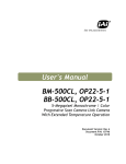
Phone Numbers
Departments
Contact
Information
MARKETING/PRODUCT
FEEDBACK
+1-301-444-2006
CUSTOMER SUPPORT /
RMA REQUESTS
+1-240-460-8833
QUALITY MANAGER
+1-301-444-2045
SALES
+1-301-515-0036
Table 1: Phone Numbers
Email Addresses
Departments
Contact Information
PRODUCT FEEDBACK
[email protected]
CUSTOMER SUPPORT /
RMA REQUESTS
[email protected]
QUALITY MANAGER
[email protected]
SALES
[email protected]
Table 2: Email Addresses
PCTEL, Inc.
Page 16
Warranty Information
Revision F
SeeGull® MX Hardware Reference Manual
OR OTHERWISE, NOR SHALL PCTEL BE
LIABLE TO BUYER FOR ANY AMOUNT
EXCEEDING THE PURCHASE PRICE OF
THE PRODUCT.
8.4.
Return Material Authorization
Procedure for the SeeGull MX
Scanning Receivers
NOTICE: There are no user serviceable parts
inside the SeeGull Receiver. Any tampering with
the components within the unit will void any
applicable warranties.
Warranty Procedures
See Return Material Authorization (RMA)
Process further below.
8.3.
Calibration Notice
Note: PCTEL recommends having the
SeeGull MX Scanning Receiver recalibrated
every 2 years.
SeeGull MX Scanning Receivers are
calibrated at the factory as an optional service
from PCTEL. PCTEL recommends
recalibration every 2 years in order to
maintain specified accuracy levels.
SeeGull Scanning Receivers are calibrated
for several sources of variations, including
amplitude levels, ambient temperature, input
frequency, and internal noise levels for
narrow and wide channel bandwidths.
Automated test and calibration stations use
proprietary software which performs the
calibration process with minimum human
intervention. Calibration is followed by a fully
automated production test. The test results
are stored in a central quality database and
then extracted and used for periodic quality
audits.
Every unit that passes the calibration and test
process successfully receives a Certificate of
Calibration. This Certificate is shipped back
with the unit.
The complexity of the calibration process
precludes field calibration. PCTEL
recommends returning scanning receivers to
the factory biennially to maintain the units’
exceptional measurement capability.
PCTEL, Inc.
All repairs must be performed by PCTEL
in accordance with the procedure outlined
below:
1. Complete the RMA form on the
website at:
http://rfsolutions.pctel.com/rfs_rma_form.cgi
Alternatively, send the information
(your name and contact information,
the company’s name and address, the
serial number and protocol of the unit,
and a description of the problem) via
email to “[email protected]”.
2. A response including an RMA number
and in-warranty or out-of-warranty
information will be provided within 24
hours, or the next working day.
3. Please ship the unit to:
PCTEL, Inc.
RF Solutions
Attn: RMA Coordinator
20410 Observation Drive
Suite 200
Germantown, MD 20876
+1 240.460.8833
4. Reference PCTEL’s RMA number on
all shipping documentation.
Note: Units returned to PCTEL without an RMA
number cannot be processed.
Page 17
Revision F
SeeGull® MX Hardware Reference Manual
9. Accessories and Service Options
9.1.
Accessories
Indoor Kits, Battery Packs
Part
Number
SeeGull MX Scanning Receiver Accessories
OP154
UNIV INPUT AC/12VDC ADPT.
OP153
INDOOR KIT – MX
INCLUDES BACKPACK, BATTERY KIT AND
PC TO SCANNING RECEIVER CABLE;
MUST PURCHASE INDOOR ANTENNA
SEPARATELY
OP156
BATTERY KIT - MX
INCLUDES BATTERY WITH INTEGRATED
CHARGER, BATTERY CABLE, US POWER
CORD AND ADAPTER FOR EU
OP158
SPARE BATTERY/CHARGER CABLE– MX
Cables
Part
Number
Description
OP152
MX POWER CABLE, BATTERY KIT – 12
FEET (3.7 METERS)
OP157
MX POWER CABLE, BATTERY KIT – 8
FEET (2.4 METERS)
OP223
MX POWER CABLE, VEHICLE LIGHTER – 9
FEET (2.75 METERS)
OP224
MX USB A-MINI DATA CABLE – 6 FEET (1.8
METERS)
OP225
ADAPTER, SMA PLUG TO SMB JACK
Description
Table 5: SeeGull MX Indoor Kit Accessories
9.2.
Service Options
Table 3: SeeGull MX Cables and Connectors
SeeGull MX Service Option
Antennas
Part Number
Calibration Services
Description
OP034H
ANT, GPS HIGH GAIN
OP078H
ANT, 698-2300 MHZ MULTIBAND MAG. MOUNT,
HIGH PERFORMANCE
OP079H
ANT, 698-2300 MHZ MULTIBAND MAG. MOUNT W/
GPS, HIGH
PERFORMANCE
OP216
ANT, 1700-2700 MHZ
MULTI-BAND MAG MOUNT
OP217H
ANT, 1700-2700 MHZ
MULTI-BAND MAG MOUNT
W/ GPS
Part
Number
Description
OPS103
CALIBRATION CHECK:
SEEGULL MX 4 BAND RECEIVER
OPS92
CALIBRATION CHECK:
SEEGULL MX 8 BAND RECEIVER
OPS104
FULL CALIBRATION FOLLOW-ON:
SEEGULL MX 4 BAND RECEIVER
OPS93
FULL CALIBRATION FOLLOW-ON:
SEEGULL MX 8 BAND RECEIVER
OPS105
FULL CALIBRATION:
SEEGULL MX 4 BAND RECEIVER
OP228
INDOOR ANTENNA 7001050, 1550-2300 MHZ
OPS94
FULL CALIBRATION:
SEEGULL MX 8 BAND RECEIVER
OP229
INDOOR ANTENNA 23002700 MHZ
OPS106
EXTENDED CALIBRATION REPORT:
SEEGULL MX 4 BAND RECEIVER
OPS95
EXTENDED CALIBRATION REPORT:
SEEGULL MX 8 BAND RECEIVER
Table 4: SeeGull MX Antennas
Table 6: SeeGull MX Calibration Service
PCTEL, Inc.
Page 18
Revision F
SeeGull® MX Hardware Reference Manual
Fixed Cost Repair Service
Part
Number
Description
OPR05
RMA EVALUATION FEE:
QUOTED TO CUSTOMERS WITH UNITS
OUTSIDE OF WARRANTY WHO SEND
UNITS IN FOR EVALUATION.
ONLY CHARGED IF UNIT DOES NOT NEED
REPAIR.
IF REPAIR IS NEEDED, THE CUSTOMER
PAYS THE FIXED COST REPAIR PRICE.
THE EVALUATION FEE IS CREDITED
TOWARDS THE REPAIR.
OPR29
FIXED COST REPAIR:
SEEGULL MX 4 BAND RECEIVER
OPR24
FIXED COST REPAIR:
SEEGULL MX 8 BAND RECEIVER
Table 7: SeeGull MX Repair Service
Warranty Extensions
Part
Number
Description
OPS107
1 YR EXTENDED WARRANTY:
SEEGULL MX 4 BAND RECEIVER
OPS96
1 YR EXTENDED WARRANTY:
SEEGULL MX 8 BAND RECEIVER
Table 8: SeeGull MX Warranty Options
For further information please contact your
PCTEL sales or marketing representative.
PCTEL, Inc.
Page 19
Revision F
PCTEL, Inc.
RF Solutions
20410 Observation Drive, Suite 200,
Germantown, MD 20876 USA
Phone: +1 301 515 0036 Fax: +1 301 515 0037
www.rfsolutions.pctel.com