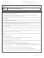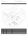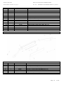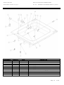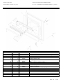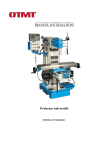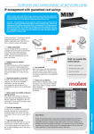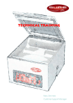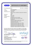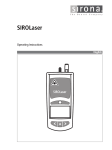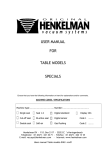
1
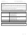
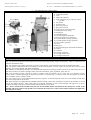
MANUAL CODE: 00861
SFERA VACUUM PACKING CHAMBER MACHINE
DATE OF ISSUE: 20/05/2010 vers_00_03
Rev. 00.01
REFERRED TO THE FIRWARE VERSION : 02_03/02.04
Vacuum Pack Chamber
Machine
Instruction manual
Use and Maintenance Manual
BUFFALO SFERA CD581
VACUUM PACKING CHAMBER MACHINE
EN
Page 1
of 28
MANUAL CODE: 00861
SFERA VACUUM PACKING CHAMBER MACHINE
DATE OF ISSUE: 20/05/2010 vers_00_03
Rev. 00.01
REFERRED TO THE FIRWARE VERSION : 02_03/02.04
CONTENTS
0.0 MANUAL SYMBOL KEY ________________________________________________________________________________ 4
1.0 GENERAL INFORMATION ____________________________________________________________________________ 4
1.1 PRODUCT INFORMATION ____________________________________________________________________________ 4
1.2 MANUFACTURER INFORMATION ______________________________________________________________________ 4
1.3
IDENTIFICATION OF PRODUCT VIA THE IDENTIFICATION LABEL ________________________________________ 5
2.0
WARNINGS _________________________________________________________________________________________ 5
2.1
EXPLOSIVE HAZARD ________________________________________________________________________________ 6
2.2
ENVIRONMENTAL HAZARD __________________________________________________________________________ 6
2.3
LESSER HAZARDS ___________________________________________________________________________________ 6
2.4
ELECTRICAL HAZARD _______________________________________________________________________________ 7
2.5
BURN HAZARD _____________________________________________________________________________________ 7
2.6
CORROSIVE HAZARD ________________________________________________________________________________ 7
2.7
USER OBLIGATIONS_________________________________________________________________________________ 8
2.8 ASSISTANCE AND MAINTENANCE _____________________________________________________________________ 8
3.0
TECHNICAL SPECIFICATIONS ________________________________________________________________________ 9
4.0
FIELD OF USE______________________________________________________________________________________ 9
4.1
MACHINE DETAIL DESCRIPTION _____________________________________________________________________10
5.0 INSTALLATION ______________________________________________________________________________________10
6.0 CONTROL PANEL DESCRIPTION _______________________________________________________________________11
6.1 KEY OF THE SYMBOLS ON THE CONTROL PANEL ________________________________________________________11
7.0 OPERATION DESCRIPTION ___________________________________________________________________________12
7.1 CYCLE PRESSURE PROGRAMMING ____________________________________________________________________12
7.2 PROGRAMMING THE WORKING CYCLE AND PROGRAMME SELECTION ____________________________________13
7.3 PROGRAMMING THE EXTRA VACUUM TIME ____________________________________________________________13
7.4 KEYBOARD FUNCTIONS AND MEMORIES _______________________________________________________________13
7.4.1 SAVE BUTTON - DATA SAVING ________________________________________________________________________13
7.4.2 STOP BUTTON ______________________________________________________________________________________13
7.4.3 OK BUTTON ________________________________________________________________________________________13
7.4.5 ON/STANDBY BUTTON _______________________________________________________________________________14
7.4.6 SELECT BUTTON ___________________________________________________________________________________14
7.4.7 STANDBY FUNCTION ________________________________________________________________________________14
7.5 FUNCTION AND PROGRAMMING OF GAS INLET _________________________________________________________14
7.6 TABLE OF PERCENTAGES OF GAS BASED ON FOOD AND GAS MIXTURES ___________________________________15
7.7 SETTING THE SEALING TIME __________________________________________________________________________16
7.8 CYCLE NUMBER DISPLAY _____________________________________________________________________________16
7.9 SOFT START FUNCTION ACTIVATION ___________________________________________________________________16
7.10 ACTIVATING THE PIECE-COUNTING FUNCTION ________________________________________________________16
7.11 RESETTING FACTORY SETTINGS, LOADING DEFAULTS __________________________________________________17
Page 2
of 28
MANUAL CODE: 00861
SFERA VACUUM PACKING CHAMBER MACHINE
DATE OF ISSUE: 20/05/2010 vers_00_03
Rev. 00.01
REFERRED TO THE FIRWARE VERSION : 02_03/02.04
7.12 LAMP ON / OFF AND ADJUSTMENT (FOR VERSIONS WITH LAMP) _________________________________________17
8.0 SUCTIONING VAPOUR AND LIQUIDS, HIGH MOISTURE CONTENT PRODUCTS, SEMI-LIQUIDS OR FOAMY
PRODUCTS _____________________________________________________________________________________________17
8.1 PUMP OIL DEHUMIDIFICATIO CYCLE __________________________________________________________________18
8.2 CALIBRATING THE VACUUM SENSOR __________________________________________________________________18
8.3 VESSEL VACUUM ASPIRATION VACUUM OR EXTERNAL VACUUM WITHOUT BAG SEALING ____________________18
8.4 PUMP OIL REPLACEMENT ____________________________________________________________________________19
9.0 CLEANING _________________________________________________________________________________________19
10.0
Guarantee _________________________________________________________________________________________20
11.0 IF THE MACHINE DOES NOT WORK ___________________________________________________________________21
12.0 EXPLODED VIEW OF SFERA CD581 ___________________________________________________________________22
OVERALL EXPLODED VIEW GRID _________________________________________________________________________22
12.1 EXPLODED VIEW OF LAMP FOR ALL MODELS __________________________________________________________23
EXPLODED VIEW GRID OF LAMP _________________________________________________________________________23
12.2 EXPLODED VIEW OF BASE ___________________________________________________________________________24
EXPLODED VIEW GRID OF BASE __________________________________________________________________________24
12.3 EXPLODED VIEW OF CHAMBER ______________________________________________________________________25
EXPLODED VIEW GRID OF CHAMBER _____________________________________________________________________25
12.4 EXPLODED VIEW OF COVER _________________________________________________________________________26
EXPLODED VIEW GRID OF COVER ________________________________________________________________________26
12.5 EXPLODED VIEW OF SEALING BAR ___________________________________________________________________27
EXPLODED VIEW GRID OF SEALING BAR __________________________________________________________________27
13.0 DECLARATION OF CONFORMITY _____________________________________________________________________28
Page 3
of 28
MANUAL CODE: 00861
SFERA VACUUM PACKING CHAMBER MACHINE
DATE OF ISSUE: 20/05/2010 vers_00_03
Rev. 00.01
REFERRED TO THE FIRWARE VERSION : 02_03/02.04
0.0 MANUAL SYMBOL KEY
IMPORTANT WARNING!
CONSULT THE MANUAL!
ATTENTION !
DANGER !
BURN HAZARD !
HOT SURFACE!
KEEP AWAY FROM
CHILDREN!
RECYCLING
RISK OF ELECTRIC
SHOCK
EXPLOSIVE
HAZARD
CORROSIVE
HAZARD
ENVIRONMENTA
L HAZARD
ASSISTANCE AND
MAINTENANCE
1.0 GENERAL INFORMATION
Congratulations for purchasing a high quality Italian product. The manufacturer thanks you for choosing its products and is
pleased and proud to include you among its loyal customers. The manufacturer is confident that the use of this product will
bring you full satisfaction. This product has been designed with special attention to the environment. The continuing search for
environmentally friendly solutions put this product in the top of their class, the power saver function is a privilege of such an
innovative product as the one which you have purchased. When not using the machine for a few minutes, the electronic control
is set to standby, an energy saving function, to safeguard the environment, the durability of the machine over time and product
operating and maintenance costs.
Please contact us in the way and at the addresses stated in this manual. Our operators will be happy to provide all the
information necessary for proper use of the product. If you should need to contact us, we kindly ask you to please have handy
this manual, the product model you purchased and serial number of the same. This manual contains confidential information
and images and use of the information contained within is allowed only by the holder of the product. Dissemination and
duplication of all or part of the images and information contained herein without prior written permission from the
manufacturer is prohibited by law. The manufacturer, who owns the rights to this manual, reserves the right to modify to the
documentation whenever necessary without prior notice for the improvement and technological development of the product.
1.1 PRODUCT INFORMATION
This document has been created and tested with great care to provide information in a clear and reliable manner. However, express
or implied responsibility cannot be attributed to the manufacturer for writing errors or any unintended omissions contained herein.
Possible errors or omissions due to the translation of manuals in a foreign language may not be attributable to the producer of the
product, as the reference language is the original language and therefore Italian.
This manual was prepared by the manufacturer of the product and contains confidential information regarding use of the product.
You may not disclose information contained herein for any reason without prior permission from the manufacturer.
This document is protected by applicable laws relating to copyright.
The user has the obligation of reading this document carefully and following the requirements contained therein to better use the
machine and protect it for a longer time.
1.2 MANUFACTURER INFORMATION
Fourth Way, Avonmouth
Bristol,BS11 8TB
United Kingdom
Page 4
of 28
MANUAL CODE: 00861
SFERA VACUUM PACKING CHAMBER MACHINE
DATE OF ISSUE: 20/05/2010 vers_00_03
Rev. 00.01
1.3
REFERRED TO THE FIRWARE VERSION : 02_03/02.04
IDENTIFICATION OF PRODUCT VIA THE IDENTIFICATION LABEL
1) Batch number
2) Ean Code
3) product serial number
4) product model
5) manufacturer address
6) EC conformity marking
7) Waste disposal symbol
8) Machine operation voltage
9) Machine operating frequency
10) Machine power
2.0
WARNINGS
The equipment described in this manual should be installed in dry areas, sheltered from sun and rain.
Installation must be carried out by specialised personnel who are well informed about the potential dangers involved.
Use of the equipment by operators that disregard basic safety rules can cause harm to themselves or others and immediately
voids the product guarantee.
Use of this machine is reserved to well-instructed personnel who are aware of current regulations and informed about
instructions contained in this manual.
This product has been designed using the latest manufacturing technologies known today and according to existing
regulations; however, conditions which are hazardous to persons or property may arise if operating and maintenance
requirements are not complied with and necessary routine maintenance is not provided.
This machine is equipped with a suction inlet. No objects or liquids of any kind should be suctioned, including anything
gaseous, liquid or solid. Do not insert objects in the suction inlet, do not cover the suction inlet and do not suction water
vapour.
There are some openings for suction pump ventilation along the perimeter of the machine. Do not block these side openings of
the machine. In the event that the machine is set alongside other machines, leave a minimum space of 10 cm per side.
When cleaning the machine with special substances suitable for stainless steel, disconnect the machine from the mains.
Do not turn the machine over, as pump oil may leak or damage parts that should not come into contact with oil.
Do not suction liquids in the Pump, do not suction water vapour. The Suction pump is equipped with lubrication oil that, if
contaminated with other liquids, loses its original properties, with consequent destruction of the suction pump.
If using the machine in a cold location, the morning before starting a working cycle, switch on the machine, start up the cycle
lowering the cover and when the display reads that pressure has reached or exceeded -05kpa, interrupt the cycle by pressing
the stop button. Repeat this 4 / 5 times so as to heat engine oil.
Whenever it may become necessary to replace the fuse installed on the machine, only use standard fuses of the type and power
of the fuse which was previously installed on the machine. Using repaired fuses or systems that bypass the fuse is strictly
prohibited. The fuse is a protection element that is essential to proper machine operation and in preventing damage to persons
or property.
Page 5
of 28
MANUAL CODE: 00861
SFERA VACUUM PACKING CHAMBER MACHINE
DATE OF ISSUE: 20/05/2010 vers_00_03
Rev. 00.01
REFERRED TO THE FIRWARE VERSION : 02_03/02.04
IMPORTANT !! Always switch off the machine first from the ON/Standby button and then from the
power switch located on the side of the machine.
IMPORTANT! Do not run the vacuum cycle with live animals or live fish inside the chamber, as doing
so causes severe suffering to animals and results in certain death, constituting a serious violation of
fundamental rights of animal life.
2.1
EXPLOSIVE HAZARD
Do not install the machine in explosive or potentially explosive environments. Do not install the machine near flammable
materials. Ventilate the environment fully before using the machine when using solvents, alcohol-based products or
flammable sprays.
Do not suction substances or products containing solvents, alcohol, gasoline or other explosive or potentially explosive
products, do not suction substances or products with a low boiling point that can generate explosive vapours or gases,
potentially explosive or harmful to human health. During sealing, very high temperatures are reached, creating very
dangerous and explosive situations.
Never use flammable or explosive gases with devices equipped with a gas injection system, as doing so can be very dangerous.
Follow gas supplier directions for proper use. Gases listed for preservation and that can be used without risk to the safety of
persons and property: nitrogen N2 , carbon dioxide CO2, mixtures of nitrogen and carbon dioxide N2 - CO2.
Do not run the vacuum cycle with cylinders or spray cans inside the chamber as they may explode.
2.2
ENVIRONMENTAL HAZARD
This product complies with EU Directive 2002/96/EC. The wheeled bin WEEE symbol indicates that the product,
at the end of its useful life, must be handled separately from normal household products and should be taken to a
recycling centre specialising in the recovery of electric and electronic products, or to the reseller when purchasing
a similar appliance. The user is responsible for delivering the equipment to the recycling centre at the end of its
life.
Proper collection for ensuing recycling, treatment and environmentally compatible disposal helps to prevent
possible negative environmental and health effects and promotes the recycling of materials which make up the
product. For further information regarding available collection systems, contact your local waste disposal service.
At the end of product life, dispose of the product according to regulations in force at the time of disposal in the country where
registered. Before being disposed of , the product must be free of all components that must be disposed of in different ways. Do
not open the gas springs used to open the cover, as they are sealed at a very high pressure, around 200 bar, and therefore
attempting to open them can be extremely dangerous. Gas springs are to be disposed of after being emptied and therefore it is
necessary to rely on a disposal centre for hazardous waste.
2.3
LESSER HAZARDS
Keep out of reach of children. The machine is not suitable for use by children or adolescents.
Page 6
of 28
MANUAL CODE: 00861
SFERA VACUUM PACKING CHAMBER MACHINE
DATE OF ISSUE: 20/05/2010 vers_00_03
Rev. 00.01
2.4
REFERRED TO THE FIRWARE VERSION : 02_03/02.04
ELECTRICAL HAZARD
Before powering up the machine, check that everything is in accordance with the use made of it. Verify that any safety
protections are efficient and that, in the country of machine use, the outlet complies with the plug mounted on the machine
and complies with voltage, frequency and outlet power, with respect to reported data contained on the machine identification
label. The machine can be connected to the mains supply only after these checks have been performed. Failure to comply with
these requirements will void the guarantee.
Electrical connection of the machine to the mains is allowed only by qualified personnel. Regularly check the electrical
machine parts to verify conditions. In the event of any scratching, crushing, abrasions or burning of the network cable or
other electrical conductor, immediately unplug the machine from the mains and call for service. Do not use the machine until
the problem has been resolved. If the operation is considered too dangerous, immediately contact an electrician or technical
assistance. Do not operate the machine; damaged electrical equipment should be replaced immediately by qualified personnel.
There are some openings for suction pump ventilation along the perimeter of the machine. Never place objects into the slits as
this causes a risk of electric shock. Do not wash the machine with steam, running water or water jets, which are prohibited in
the perimeter of machine use, risk of electric shock. When cleaning the machine, disconnect the machine from the mains.
Before each oil change or any technical intervention, disconnect machine power from the mains.
Do not touch metal machine parts with damp or wet hands.
Do not pull the power cable to disconnect it from the mains
Verify that the machine is connected to the electrical outlet and that the outlet is connected to grounding as required by
applicable law. The machine must never be used without grounding for any reason. The manufacturer cannot be held
responsible for any damage to persons or property due to lack of connection to grounding of the electrical system..
Keep the mains cable installed on the machine away from heat sources as they may melt, becoming irreparably damaged.
In the event that the machine becomes inoperative with serious malfunctions or exposed electrical parts, with danger to
persons or property, notify receiving personnel to make the machine harmless. Use a sign to clearly mark the problem and
hazard of with machine operation run without repair.
2.5 BURN HAZARD
Do not touch the sealing bar immediately after a cycle, burn hazard. Avoid touching the sealing bar in any case .
2.6
CORROSIVE HAZARD
Clean the machine with products suitable for material used for its construction. Do not use acids or aggressive substances
which may damage the machine structure and cause damage to persons or property. For better identification of products
suitable for cleaning, see the maintenance and cleaning section.
Page 7
of 28
MANUAL CODE: 00861
SFERA VACUUM PACKING CHAMBER MACHINE
DATE OF ISSUE: 20/05/2010 vers_00_03
Rev. 00.01
2.7
REFERRED TO THE FIRWARE VERSION : 02_03/02.04
USER OBLIGATIONS
This document is considered an integral part of the equipment that you have purchased and as such should be treated and
kept for the lifetime of the product. In the event of sales of the product, this document must be provided to the new owner.
The buyer must read and have all operators making use of the machine read this document. Its consultation must be permitted
whenever necessary.
Not complying with the instructions in this manual may impair the proper functioning of the system and can severely damage
the equipment, effectively reducing its operating life. The incorrect installation of equipment can cause severe and permanent
damage to persons and/or property. Incorrect installation can also cause electrocution to operators.
Failure to comply with these requirements will void the guarantee.
It is important to read the instructions in this manual carefully before installing and powering the equipment. All operations
must be restricted to specialised personnel who understand the risks and danger that can result from improper installation, by
not respecting the rules and non-compliance with the instructions in this manual. It is also important to make the correct
connections in order to prevent malfunctions caused by electrostatic discharges or false contacts. Lack of knowledge of the
information contained in the machine manual limits the use and full performance operation of the machine.
The machine manual must be kept near the machine and always available to personnel for any necessary consultations. The
manufacturer allows the buyer to keep a copy of this manual for internal use only within the buyer's factory, to prevent
degradation of the manual over time.
This document was prepared and checked with great care to give you accurate and reliable information. The manufacturer
disclaims any implicit and explicit responsibility for any omissions or alterations in it.
The contents of this manual, descriptions, images and product specifications are not binding for the manufacturer, who
reserves the right to modify without prior notice if necessary. Any errors or inaccuracies due to errors in translation into
various languages cannot be cause for complaint or attribution of responsibility borne by the manufacturer.
Removing the EC label or other labels or plates installed on the machine is strictly prohibited. In the event that this should
happen, the product guarantee will be immediately void, as well as EEC compliance. It is therefore the responsibility of the
customer and owner of the machine to ensure that this does not happen. If the EC label should break or become illegible, the
manufacturer should be informed immediately.
2.8 ASSISTANCE AND MAINTENANCE
Perform maintenance and cleaning consistently and in a timely manner. Repairs must be performed by qualified service
assistance.
Periodically change the pump oil every 4 months in case of little activity, or every 10,000 cycles or about every 200 working
hours.
Replace pump oil with the same type of oil shown on the pump information plate. Use of a different oil will damage the pump
irreparably.
Before each oil change or any technical intervention, disconnect machine power from the mains. Perform maintenance and
cleaning consistently and in a timely manner. Repairs must be performed by qualified service assistance.
No partial or substantial changes of any kind to the machine are allowed without prior authorisation from the manufacturer.
Any malfunctioning, defective, worn or broken parts must be replaced immediately for proper machine operation and for
safety of personnel using the machine. All changes and repairs must be performed by qualified personnel only. Repairs under
guarantee shall be valid and recognised as such only if performed by personnel who are qualified and expressly authorised by
the manufacturer.
Clean the machine regularly. Suitable cleaning contributes to improved conservation, better product hygiene, and greater
durability.
Page 8
of 28
MANUAL CODE: 00861
SFERA VACUUM PACKING CHAMBER MACHINE
DATE OF ISSUE: 20/05/2010 vers_00_03
Rev. 00.01
REFERRED TO THE FIRWARE VERSION : 02_03/02.04
For products with a three phase pump, connect all three phases. Connecting only two of the three will cause the engine to
damage irreparably.
For three phase products, pay attention to the direction of engine rotation, verifying that the rotation is as indicated by the
arrow on the engine. Whenever the rotation is opposite to the arrow, try reversing the connection of the two outer phases (R
and T) and try again. If the direction is reversed again, try to invert other two phases, until the motor rotates in the correct
direction.
Be careful not to run the engine for a long time in the wrong rotation, as the pump will break down irreparably. During the
rotation test, the engine should not run for more than a few seconds (max2 /3).
Verify that the machine is connected to the electrical outlet and that the outlet is connected to grounding as required by
applicable law. The machine must never be used without grounding for any reason. The manufacturer cannot be held
responsible for any damage to persons or property due to lack of connection to grounding of the electrical system..
3.0 TECHNICAL SPECIFICATIONS
230 VAC +/- 5% 50 / 60 Hz single phase
400 VAC +/- 5% 50 / 60 Hz three phase
Maximum absorbed current
with 4mq3 ,6mq3, 8mq3 single phase pump = 3 A
with 12 mq3, 18 mq3, 25 mq3 single phase pump = 5 A
with 40mq3 single phase pump = 7 A
with 40mq3 three phase pump = 7 A
with 60mq3 three phase pump = 10 A
with 100mq3 three phase pump = 15 A
Working temperature
from 10 to 40°C
Maximum power
with 4 mq3, 6 mq3, 8 mq3 single phase pump = O.6 kw
with 12 mq3,18mq3, 25mq3 single phase pump = 1.0 kw
with 40mq3 single phase pump = 1.5 kw
with 40mq3 three phase pump = 1.5 kw
with 60mq3 three phase pump = 2.0 kw
with 100mq3 three phase pump = 3.0 kw
Maximum pressure
with pump from 4 to 18 mq3 = 2 mbar / hpa
with pump from 25 to 100 mq3 = 0.5 mbar / hpa
Relative humidity
from 10 to 80 %
Oil change
every 4 months or every 200 hours of operation / every 10,000 cycles
Special versions can be created on request with customised supply voltages or dimensions.
Voltages
4.0
FIELD OF USE
SFERA was created to vacuum pack food or other products requiring vacuum in bags or containers suitable to the specific use.
Therefore, any other applications do not conform to the purpose for which the Sfera packaging machine lines were designed.
Non-compliance with the scope of use immediately voids the guarantee and cannot ensure the proper functioning of the machine
Page 9
of 28
MANUAL CODE: 00861
SFERA VACUUM PACKING CHAMBER MACHINE
DATE OF ISSUE: 20/05/2010 vers_00_03
Rev. 00.01
4.1
REFERRED TO THE FIRWARE VERSION : 02_03/02.04
MACHINE DETAIL DESCRIPTION
1) stainless steel structure
2) command keyboard
3) cover
4) LED lamp (optional)
5) rapid connection for gas injection system
(cylinder)
6) start switch
7) protective fuse
8) gas injection nozzle
9) gas injection nozzle
10) right side bag positioning limit
11) Sealing bar cover casing
12) Sealing bar
13) Chamber Bottom
14) left side bag positioning limit
15) Suction nozzle for air extraction
16) Cylinder holder carriage (optional)
17) Cylinder holder carriage (optional)
18) Gas cylinder (optional)
19) Cover
20) Bag stop
21) Patented sealing bar movement mechanism
22) Gasket
23) Chamber
24) Carriage (optional)
25) Carriage closure door
26) Carriage closure lock
5.0 INSTALLATION
5.1- Before powering up the machine, check that the pump contains oil inside to prevent irreparable damage.
5.2 - The electrical connection of the machine must be set with an appropriate voltage and frequency, which is contained on the
machine identification label.
5.3 - Do not protect the machine with fuses of a greater value than the value indicated on the machine identification label.
5.4 - The product identification label is installed on one side of the machine. To check engine oil, open the door at the rear of the
machine, see section ENGINE OIL REPLACEMENT.
5.5 - SFERA vacuum packing machines were designed and constructed to package products which are dry and moisture-free. It is
therefore possible to use them to package salami, seasoned cured meats, pasta, vegetables, meat, fish, etc.
5.6 - The operating principle is based on creating a vacuum inside the chamber, up to a value close to an absolute vacuum.
Conservation is carried out through the injection of products in a special bag or container which will subsequently be inserted
into a chamber where a vacuum is made.
5.7 - The vacuum cycle is performed automatically and in sequence, its duration depends on the size of the chamber and the flow
rate of the pump used for the vacuum.
5.8 - Sfera machines are equipped with an Buffalo patented sealing system. This mechanism is located on the machine cover and
not on the chamber bottom. This system offers an important advantage in terms of functionality and hygiene, as it allows
complete cleaning of the bottom of the chamber without hindrance of any kind.
5.9 - Always switch off the machine first from the ON/STANDBY button and then from the main power switch. If the
machine will not be used for long periods, turn it off from the main power switch. Switch off the machine each night from
the main power switch.
Page 10
of 28
MANUAL CODE: 00861
SFERA VACUUM PACKING CHAMBER MACHINE
DATE OF ISSUE: 20/05/2010 vers_00_03
Rev. 00.01
REFERRED TO THE FIRWARE VERSION : 02_03/02.04
6.0 CONTROL PANEL DESCRIPTION
6.1 KEY OF THE SYMBOLS ON THE CONTROL PANEL
1) LED for reserved functions.
2) LED indicating the ignition of the extra vacuum timer
function .
3) LED indicating machine standby.
4) LED indicating power On (machine on).
5) 3-digit working pressure display quadrant.
6) LED indicating display of pressure in Kpa.
7) LED indicating display of pressure in Bar.
8) LED indicating display of pressure in Psi.
9) LED indicating display of pressure in mmHG.
10) 2-digit extra Vacuum time display quadrant.
11) LED indicating vacuum cycle start upon pump ignition.
12) 2-digit extra display of time or percentage of Gas
injection.
13) When lit, LED indicating gas inlet cycle start.
14) 2-digit extra Sealing time display quadrant.
15) When lit, LED indicating sealing cycle start.
16) Quadrant of user-programmable memories. LED light
corresponds to the relative memory.
17) SAVE button used to update data in memory
following programming.
18) ON/Standby button indicating machine on and
off.
19) STOP button used to interrupt a working cycle or
cancel an operation.
20) OK button for confirmation and acceptance of an
operation.
21) SELECT button to select functions and menu.
22) MEMORY button to retrieve memories.
23) Welding Timer DOWN BUTTON reduces sealing
time.
24) Welding Timer UP BUTTON increases sealing
time.
25) Gas Injection Timer DOWN BUTTON reduces
gas injection time/percentage.
26) Gas Injection Timer UP BUTTON increase gas
injection time/percentage.
27) Vacuum Timer DOWN BUTTON reduces extra
vacuum time.
28) Vacuum Timer UP BUTTON increase extra
vacuum time.
29) Pressure Meter DOWN BUTTON reduces
working pressure value.
30) Pressure Meter UP BUTTON increases working
pressure value.
Page 11
of 28
MANUAL CODE: 00861
SFERA VACUUM PACKING CHAMBER MACHINE
DATE OF ISSUE: 20/05/2010 vers_00_03
Rev. 00.01
REFERRED TO THE FIRWARE VERSION : 02_03/02.04
7.0 OPERATION DESCRIPTION
Connect the mains cable to a mains socket with appropriate
Fig.7.0.1
voltage for the voltage indicated on the device identification
plate. Press the power switch so that it lights up.
To start a working cycle:
1) Insert a bag with the product to be preserved, resting the bag
with the open side on the sealing bar Fig. 1
2) Put the two upper and lower Gas injection nozzles inside the
bag between the two seals, as per Fig. 1.
3) Set desired parameters.
4) Close the cover and wait until the end of the cycle, indicated
by the message "end" on the display and by the opening of
the cover
1) maximum bag positioning limit
ATTENTION!! sharp or pointed products can
2) gas injection nozzle
puncture the bag: remove tips or sharp edges
3) gas injection nozzle
before putting the product under vacuum.
7.1 CYCLE PRESSURE PROGRAMMING
Proceed as follows to programme working pressure:
1) with the machine on and the cover open (cycle off)
2) press the + button (fig.7.2.1) on the Pressure Meter quadrant to increase the value, maximum-99 Kpa
3) press the - button (fig.7.2.1) on the Pressure Meter quadrant to reduce the value, minimum -50 Kpa
4) press the Save button to update data.
The machine must be used at -99 Kpa for an ideal vacuum cycle.
The machine mode can be changed from pressure cycle to time cycle.
The pressure cycle is preferable because the electronic control measures the vacuum level of the chamber and
establishes when the cycle is complete. In the time cycle, it is the operator who determines the machine cycle time
by assigning an operating time. In this case, pressure control is ignored by the system, but still appears on the
pressure meter quadrant.
Proceed as follows to pass from pressure control to time control and vice-versa:
1) with the machine on and the cover open (cycle off)
2) press the + e – (fig. 7.2.1) buttons on the Pressure Meter at the same time for about 3 seconds.
The time function is selected when the pressure meter quadrant indicates 0 while the vacuum bag (fig. 7.2.2)
indicates the cycle time ( default 99 seconds). Upon cycle start-up, the pressure meter quadrant (fig. 7.2.1) displays
the pressure, while the vacuum timer quadrant (fig. 7.2.2) displays the decreasing working timer. When this timer
gets to zero, the suction cycle ends and the functions sequence finishes. To return to pressure control, repeat the
operation described above.
Time operation can be particularly useful in the unlikely event that the pressure sensor should break, passing to the
time procedure, as the machine will not stop.
If the time cycle mode is selected, proceed as follows to set cycle time:
1) with the machine on and the cover open (cycle off)
2) press the + button (fig.7.2.2) on the Vacuum Timer quadrant to increase the value.
3) press the - button (fig.7.2.2) on the Vacuum Timer quadrant to reduce the value.
4) Press the SAVE button to update data.
In the event of time cycle setting, some test cycles are necessary to test the effectiveness of the working cycle. A
time that is too low cannot guarantee a good vacuum cycle and the cycle time depends on the volume of the
chamber and the size of the suction pump. SFERA chambers are among the largest chambers on the market with
the same kind of sealing bar and pump.
Fig.7.2.1
Fig.7.2.2
Pressure can be displayed in 4 units of measure Fig. 7.2.1: Kpa, Bar, Psi and mmHG. Proceed as follows to pass
from display from one unit of measure to another:
1) press the SELECT button with the machine on and the vacuum cycle running and with the cover down.
Attention !! Not setting the machine to its optimum settings can affect proper food
preservation.
Page 12
of 28
MANUAL CODE: 00861
SFERA VACUUM PACKING CHAMBER MACHINE
DATE OF ISSUE: 20/05/2010 vers_00_03
Rev. 00.01
REFERRED TO THE FIRWARE VERSION : 02_03/02.04
7.2 PROGRAMMING THE WORKING CYCLE AND PROGRAMME SELECTION
The SFERA vacuum packing chamber machine series is equipped with
Fig.7.1.1
sophisticated control logic which is able to manage automatic working
cycles. The digital volumetric sensor it is equipped with measure the
vacuum level inside the chamber with great precision and reliability.
Thanks to the programmable digital electronic control, the operator can
choose up to 13 custom operating programmes, different from each other for
all the parameters that the machine uses for the working cycle.
As can be seen in figure Fig. 7.1.1 the control panel is easy and intuitive and
contains all the information necessary for the user.
7.3 PROGRAMMING THE EXTRA VACUUM TIME
Extra vacuum time is a very useful time for optimising the vacuum level inside the chamber. When the system
detects maximum pressure of -99 Kpa, it interprets that the vacuum has been reached and therefore that the cycle
can end. However, there is still a small percentage of air inside the chamber, activating the extra vacuum timer
function to continue to suction the pump for the set amount of seconds in order to extract as much air as possible.
The Sfera series is set to obtain an ideal time/performance ratio with the extra vacuum timer set to 10 seconds.
Obviously, increasing this time increases the volume of air to be extracted. It may seem paradoxical that such a
high amount of time is necessary, but it is not, as the more the vacuum increases, the less air remains inside the
chamber, so the pump has to work for a long time to extract small amounts of residual air, since the air in this case
is very thin.
Fig. 7.3.1
Proceed as follows to programme extra vacuum time:
1) with the machine on and the cover open (cycle off)
2) press the + (fig.7.3.1) button on the Vacuum Timer quadrant to increase value.
3) press the - (fig.7.3.1) button on the Vacuum Timer quadrant to reduce the value.
Press the SAVE button to update data.
Attention !! Extra vacuum time is only active if the pressure value is set to -99Kpa. In case
of time cycle activation, it will not be possible to set an extra vacuum time.
7.4 KEYBOARD FUNCTIONS AND MEMORIES
The Sfera control keyboard is composed of different buttons, some + and - to change associated quadrant
parameters and other general and specific functions. The general and specific function buttons are as follows:
SAVE button : to save selected parameters, to update in memory
STOP button : to interrupt a programme, to interrupt a working process or cycle
OK button : to confirm a selection or to end a suction cycle during a working cycle
when pressure exceeds -50Kpa
MEMORY button : to recall programme memories.
ON/STANDBY button : to switch the machine on and off, before switching off the main switch, to
reactivate after standby.
SELECT button : to select parameters or access menus
FIG. 7.4.1
FIG. 7.4.2
7.4.1 SAVE BUTTON - DATA SAVING
Press the SAVE button after programming to update data in the memory
7.4.2 STOP BUTTON
Press the STOP button to interrupt a process. The menu will be exited or the working cycle interrupted. In this
case, the cycle will immediately stop and the bag will not be sealed.
7.4.3 OK BUTTON
Press the OK button to confirm a selection. When a vacuum exceeds -50 Kpa during a suction cycle, press the OK
button and the machine will interrupt suction and seal the bag. In this case, verify proper bag sealing as there may
be little pressure for a good sealing.
7.4.4 MEMORY BUTTON
Press the MEMORY button to retrieve various memories. SFERA is equipped with 13 user-programmable
memories. The base memory plus other 12. The base memory is indicated by 12 off LEDs on the MEMORY
panel. Each time MEMORY is pressed, the following memory is suggested, indicated by the lighting of the
corresponding LED. The memories are useful for immediate access to the most appropriate cycle for the product to
Page 13
of 28
MANUAL CODE: 00861
SFERA VACUUM PACKING CHAMBER MACHINE
DATE OF ISSUE: 20/05/2010 vers_00_03
Rev. 00.01
REFERRED TO THE FIRWARE VERSION : 02_03/02.04
be packaged, without having to change the parameters each time.
Memories can be customised to liking. Move to the desired memory by means of the MEMORY button, change
the data in their respective quadrants and press the SAVE button to update the previously selected current memory.
Use of memories is particularly appropriate if different size or thickness bags are used, or if preservation uses inert
gas. Depending on the size of the bag or food to be preserved, more or less gas can be inserted into the bag.
7.4.5 ON/STANDBY BUTTON
Press the ON/STANDBY button with the cover open. If the machine is on, it will switch off and go into standby. If
the machine is already in standby, it will reactivate for working cycle operation. When not using the machine for
more than 5 minutes, the standby function will become automatically activated as an energy saving function.
7.4.6 SELECT BUTTON
PRESS the SELECT button with the cover open to enter into the function selection menu. Press it repeatedly to
move to various parameters. If this button is pressed during the cycle, the display changes viewing of pressure in
different units of measure
7.4.7 STANDBY FUNCTION
To switch the machine on or off, press the ON/STANDBY button. If the machine will not be used for long periods,
turn it off also from the main power switch located on the side of the machine.
The ON/STANDBY button activates standby and therefore a low absorption conditions, but the electrical and
electronic parts of the machine are however powered by the mains. If this condition is not desired, switch the
machine off completely by pressing the ON/STANDBY button and then the switch on the side.
IMPORTANT !! Always switch off the machine first from the ON/Standby button and then
from the power switch located on the side of the machine. If the machine is in standby, switch
it off from the main switch
7.5 FUNCTION AND PROGRAMMING OF GAS INLET
The Sfera series is provided with a gas injection system. This function is useful in the event that the user wishes to
preserve food needing inert gas to improve storage or if the user wishes not to flatten the product with the vacuum
strength. Gases normally used are Carbon Dioxide CO2, Oxygen O2 and Nitrogen N2 or mixes of these three
gases. Table 7.6 gives an indication of the possible gas compositions based on the type of food. It is however
necessary to establish the type of gas to be used. Contact your Gas supplier, as all types of food require specific
gas or a specific mixture.
Fig. 7.5.1
The gas injection function can be disabled in two ways:
1) Setting the timer on the Timer Gas Injection quadrant to zero Fig. 7.5.1, In this case the display shows a 0
2) With the machine on and the cover open, pressing the + and - buttons on the Timer Gas Injection quadrant for
about 3 seconds Fig. 7.5.1, in this case, the display turns off completely. Repeat this operation to reactivate this
function.
There are 2 possible ways to insert gas: time and percentage modes.
The time mode functions so that, when the Timer Gas Injection is set to zero Fig. 7.5.1, the gas is injected at a
determined value for that amount of time regardless of quantity.
The percentage mode (default setting) works in such a way that, setting a certain percentage in the range from 1%
to 60%, the system automatically inserts the percentage of gas requested. The display value is the same, so the
operator must be familiar with the selected mode at the time of use.
In both cases, the operator will have to perform some tests before deciding whether the required gas inside the bag
is suitable for the request. It is not possible to insert a volume of gas exceeding -0.40 kPa, as there would not be
sufficient power for bag sealing. If a high percentage of gas over 40% is required, check that the machine properly
seals the bag as the pressure could be too low for sealing.
Adjust the gauge located on the cylinder to a maximum pressure of 1 Bar. The lower the pressure, the higher the
injection precision of the quantity of gas in the bag. The regulation of gas output from the cylinder is essential for
increased gas injection precision. Some verification tests are therefore recommended.
Fig. 7.5.2
Fig. 7.5.3
Proceed as follows to enable time or percentage modes:
1) With the machine cover open, repeatedly press the SELECT button Fig. Fig. 7.5.2, until you reach the
“GAS PErCn” symbol that indicates gas injection in percentage, or “GAS tInEr” that indicates gas
injection in time.
2) press the + and - buttons on the WELDING TIMER quadrant Fig. 7.5.3, to move from “GAS PErCn” in
percentage to “GAS tInEr” gas in time.
3) Press SAVE to confirm the desired mode.
Page 14
of 28
MANUAL CODE: 00861
SFERA VACUUM PACKING CHAMBER MACHINE
DATE OF ISSUE: 20/05/2010 vers_00_03
Rev. 00.01
REFERRED TO THE FIRWARE VERSION : 02_03/02.04
Select “GAS PErCn” for percentage injection.
Select “GAS tInEr” for time injection.
Proceed as follows to vary gas injection time or percentage based on the previous selection (percentage is the
default setting):
1) with the machine on and the cover open.
2) press the + (Fig.7.5.1) button on the Timer Gas Injection quadrant to increase value.
3) press the - (Fig.7.5.1) button on the Timer Gas Injection quadrant to reduce value.
4) Press the SAVE button to update data.
To use the gas injection function, connect the cylinder to the machine. See 4.1 MACHINE DETAIL
DESCRIPTION to identify the attachment nozzle for gas injection. Adjust cylinder output pressure by means of
the reducer gauge on the cylinder. Pressure must be regulated between 0.5 and 1 bar maximum.
Attention !! to determine the percentage of gas to insert, whether with the time or percentage
mode, some test cycles must be carried out. All foods require a specific gas for better
preservation. In this respect and to avoid using unsuitable gas, contact companies that
specialise in preserving food with inert gases.
7.6 TABLE OF PERCENTAGES OF GAS BASED ON FOOD AND GAS MIXTURES
(O2) OXYGEN
(CO2)
PRODUCT
%
CARBON DIOXIDE %
(N2)
NITROG
EN %
80
-
Sliced salami / cured meats
20
Roasted meat
80
20
Canned drinks
100
Biscuits, baked goods, coffee, sandwich bread / bread,
100
chocolate,
Yogurt, pasta dough, trout, farmed fish
Fresh meat
70 – 80
30-20
Freeze-dried meat and spices, minced meat, fruit juices,
100
Potatoes, chips, snacks, pasta, oil, wine
Chicken
75
25
Fresh mozzarella cheese
20-0
80-100
Cheese, cream, butter, margarine, hard cheese
100
Salad, parsley
50
50
Powder milk, pizza
30
70
Dry and powder yeast
100-0
0-100
Apples
2
1
97
Sliced bacon
35
65
Toast / toasted bread, pre-cooked
80
20
Fresh pasta, tortellini, lasagne
70-100
30-0
Anchovy, sardines
60
40
Whitefish
30
40
30
tomatoes
4
4
92
Sliced cutlets
70
20
10
Attention! The above table is for information purposes only and purely indicative and should not be used as
an outline for food preservation. For proper food preservation, contact your gas supplier who will present an
actual analysis of your needs.
Page 15
of 28
MANUAL CODE: 00861
SFERA VACUUM PACKING CHAMBER MACHINE
DATE OF ISSUE: 20/05/2010 vers_00_03
Rev. 00.01
REFERRED TO THE FIRWARE VERSION : 02_03/02.04
7.7 SETTING THE SEALING TIME
It is possible to customise the bag sealing time depending on the thickness of the bag to be used. The higher the set
time, the higher the bag sealing temperature, therefore sealing thicker bags. It is important to set an appropriate
value so that the bag does not melt in the sealing area or that it does not seal properly. Therefore, after having
changed the sealing time, at the end of some sealing cycles, wait about 10 seconds until the bag is cooled down
and try to open it with force along the back of the seal. If you cannot open it, the time set is correct. Also verify
that there are no gaps along the seal and that the seam is uniform. Small imperfections along the seal can be a
source of slow air infiltration into the bag with consequent damage to products.
Fig. 7.7.1
Proceed as follows to vary sealing:
1) with the machine on and the cover open.
2) press the + (fig.7.7.1) button on the WELDING TIMER quadrant to increase value.
3) press the - (fig.7.7.1) button on the WELDING TIMER quadrant to reduce value.
4) Press the SAVE button to update data.
7.8 CYCLE NUMBER DISPLAY
The Sfera series is equipped with two cycle counters. One counts total cycles and is non-resettable, the other is
resettable and counts partial cycles.
The partial cycle counter can be particularly useful in cases of machine hire.
Proceed as follows to view the total cycle counter:
1) press the + button in the VACUUM TIMER panel Fig. 7.8.2 together with the + button on the
PRESSURE METER panel FIG. 7.8.1
Proceed as follows to view the partial cycle counter:
1) press the - button in the VACUUM TIMER panel Fig. 7.8.2 at the same time a button - on the PRESSURE
METER panel FIG. 7.8.1
Proceed as follows to reset the partial cycle counter:
1) with the machine off and the cover open, press the STOP button, the - button on the PRESSURE METER panel
and the - button on the VACUUM TIMER panel at the same time for about 2 seconds.
7.9 SOFT START FUNCTION ACTIVATION
The Sfera series is equipped with a double control for the slow introduction of air into the chamber: one a default
electronic control and one a mechanical Optional, with greater performance than the electronic system.
The mechanical system has a knob on the front or side of the machine, which rotates both clockwise and
counterclockwise to adjust the rate of return of air in the chamber at the end of the cycle.
The electronic system chokes the air return solenoid valve with very fast on/off cycles. The knob mechanical
system is more efficient than the electronic system.
The mechanical or electronic soft air systems are particularly useful to prevent that the bag has too rapid a
withdrawal around the product at the end of the cycle. If, for example, an especially edged or cutting bag was
introduced: when the bag is withdrawn too suddenly at the end of the cycle, the bag could become punctured.
Activating the SOFT AIR function, the air solenoid valve is choked. In this way, the bag wraps around the product
more slowly.
Proceed as follows to activate this function:
1) with the machine off and the cover open, press the SELECT button FIG. 7.9-1 until you reach the SoFtAir
menu. The message On will appear on the WELDING TIMER if it has been enabled, or OFF if it is
disabled.
2) press the + button on the WELDING TIMER panel to activate the function or the - button on the same
quadrant to deactivate the function FIG.7.9.2
3) Press the SAVE button to confirm and stop to exit the menu.
Attention !! Before putting products that may contain sharp or cutting parts in the vacuum,
such as meat on the bone or hard cheese with skin, such as Parmigiano Reggiano, eliminate
these points or sharp edges to prevent puncturing the bag.
7.10 ACTIVATING THE PIECE-COUNTING FUNCTION
The Sfera series is equipped with a piece-counting function. If the user would like to package a certain number of
pieces, this function can be set so that the operator is free from having to continually check the number of pieces
worked. Proceed as follows to activate the piece-counting function:
1) with the machine stopped and the cover open, press the SELECT button until you reach menu 000
CYCLES, 7.10.2
2) to set the desired number of cycles, press the + and - buttons on the PRESSURE METER quadrant, 7.10.2
Fig. 7.8.1
Fig. 7.8.2
Fig. 7.9.1
Fig. 7.9.2
Fig. 7.10.1
Fig. 7.10.2
Page 16
of 28
MANUAL CODE: 00861
SFERA VACUUM PACKING CHAMBER MACHINE
DATE OF ISSUE: 20/05/2010 vers_00_03
Rev. 00.01
REFERRED TO THE FIRWARE VERSION : 02_03/02.04
3) press the Save button to update data FIG. 7.10.1
4) Press STOP to exit from the menu.
After each working cycle, the number of remaining cycles is shown in a decreasing number. When all cycles have
been carried out, the message "End CYCLES" will appear. Press the STOP button to unlock, otherwise the control
will remain locked and no other functions can be performed.
7.11 RESETTING FACTORY SETTINGS, LOADING DEFAULTS
Factory settings can be reset at any time. This can be useful in the event of machine malfunction or erred settings.
Proceed as follows to load DEFAULT data:
1)
switch off the machine
2)
press SELECT, switch on the machine keeping the SELECT button pressed. As soon as
"DEFAULT" appears, release the button. FIG.7.11.1
Default data has been reset.
7.12 LAMP ON / OFF AND ADJUSTMENT (FOR VERSIONS WITH LAMP)
The compartment lamp (optional) lights up every time the machine is powered and stays lit during the working
cycle and during working breaks. If the machine is not used for about 5 minutes, the lamp switches off and the
machine is placed in standby. Lamp brightness can be switched on, off or adjusted as desired. Proceed as follows
to programme the lamp:
1) with the cover open and the machine stopped, press the SELECT button until you reach the LIGHT
parameter on the WELDING TIMER quadrant. The value of light brightness will be shown, from a
minimum of 0 to a maximum of 40 units. FIG.7.12.2
2) press the + and - buttons on the WELDING TIMER quadrant can increase or reduce brightness or turn off
the lamp if put on OFF. FIG.7.12.2
3) Press the SAVE button to update data. FIG.7.12.1
4) press STOP to exit from the menu. FIG.7.12.1
The next time the machine will be switched on, the last programmed brightness value will be kept. If set to OFF,
the lamp will remain switched off
ATTENTION !! always switch off the machine first from the ON/STANDBY button and then
from the main power switch. If the machine will not be used for long periods, turn it off from
the main power switch. Switch off the machine each night from the main power switch.
FIG 7.11.1
FIG 7.11.1
FIG. 7.12.1
8.0 SUCTIONING VAPOUR AND LIQUIDS, HIGH MOISTURE CONTENT PRODUCTS, SEMI-LIQUIDS OR FOAMY
PRODUCTS
Special attention should be paid when running cycles with liquid, foamy, or hot products containing water vapours, as the suction
pump circuit contains oil and is particularly vulnerable to liquid and vapour suction. In fact, the main cause of suction pump
failure is due to the intake of liquids or water vapour. Whenever preserving products containing liquids, vacuum settings must be
changed to avoid suctioning the water vapour generated by the product, even if it is cold, and due to a physical process for which
the boiling point of water decreases with increasing the percentage of the vacuum. Therefore, set a value appropriate for avoiding
boiling the water contained within the product, such as -0.95 kPa, to therefore avoid that water vapour generated from boiling,
even if cold, become suctioned by the pump, possibly causing damage.
Avoid suctioning cooked products that are still hot and which spontaneously generate vapour. Allow products to cool before
suctioning. Avoid suctioning products with an elevated moisture content with maximum vacuum settings. Also in this case, set
the vacuum value in such a way that the vapour generated by liquid boiling, even if cold, become suctioned. In the event that
products containing liquids should be suctioned, dehumidify the engine oil through an engine oil dehumidification cycle (see
paragraph 8.1 PUMP OIL DEHUMIDIFICATIO CYCLE). Water boiling inside the chamber shows, however, proper function
of the machine. If any doubts remain regarding the operation and level reached of the vacuum, simply place a pan or bag with
100ml of water inside the chamber, set the maximum vacuum value to -99 Kpa and start the cycle. When the water starts to boil,
the maximum vacuum has been reached. Obviously, the boiling point of the water depends also on the altitude where the machine
is located. See paragraph 8.2 CALIBRATING THE VACUUM SENSOR. When boiling starts, immediately stop the cycle to
prevent water vapour becoming suctioned by the pump.
Prepare for suction of liquid, semi-liquid or foamy products in such a way that the bag become filled only 50% of its maximum
total capacity. Keep in mind that, during the suction phase, any foamy products can increase volume considerably; therefore, said
products could come out from the bag and pour into the chamber. Use the maximum possible difference in level, removing all
possible internal chamber shelves. Set the machine so that the liquid does not boil.
Attention !! Before starting packaging of any liquids, run 2 or 3 vacuum cycles or, even better, start up a
pump oil dehumidification cycle to heat up the pump and the oil. In this case, set the maximum vacuum value.
Then, set the vacuum value which does not allow liquid boiling, for example -0.97 kpa or less. This value
depends on the liquid to be preserved and by the altitude of the machine location. Start a packaging cycle and
Page 17
of 28
MANUAL CODE: 00861
SFERA VACUUM PACKING CHAMBER MACHINE
DATE OF ISSUE: 20/05/2010 vers_00_03
Rev. 00.01
REFERRED TO THE FIRWARE VERSION : 02_03/02.04
in any case avoid suctioning vapours and liquids directly into the pump.
8.1 PUMP OIL DEHUMIDIFICATIO CYCLE
The pump oil dehumidification cycle is very important and is to be carried out periodically. It helps to protect the pump from any
breakage in the event of vapour or liquid suction. This cycle allows an empirical remedy if small amounts of vapour or liquids
should be suctioned.
The solution to the problem of liquid or vapour suction is to change the oil, preserving the life of the pump over time.
Proceed as follows to carry out a dehumidification cycle:
1) with the machine stopped and the cover open, press the SELECT button until you reach message "“dEu Fo IL PP”,
2) press the OK button to confirm and STOP to exit
3) "PUS HC OU ER" will be displayed
4) lower the cover, the cycle will begin and last for 15 minutes
5) when the cycle starts, the message “ –xx DE UD PP" will appear, where xx indicates the remaining time until the cycle ends.
At the end of the cycle, the machine can be used normally. Press STOP to interrupt the cycle.
8.2 CALIBRATING THE VACUUM SENSOR
SFERA is equipped with an accurate reading digital vacuum sensor digital that is influenced by atmospheric pressure at various
altitudes, so anytime the machine is to be moved to a different altitude as well as at first installation, it is advisable to calibrate the
pressure sensor to reflect the parameters of the machine workplace.
Proceed as follows to calibrate the machine:
1) with the cover open, switch off the machine from the main mains switch, press the + and - buttons on the PRESSURE
METER quadrant,
2) switch on the machine keeping the buttons pressed and the message "SEttInG" will appear.
3) Release buttons,
4) close the cover, the machine will start the calibration cycle, which will last about 3 minutes, and will end when the cover
opens.
The machine will now be calibrated for use in its location. Whenever the machine is moved and positioned to a different altitude,
repeat calibration.
8.3 VESSEL VACUUM ASPIRATION VACUUM OR EXTERNAL VACUUM WITHOUT BAG SEALING
With the Sfera series, it is possible to suction outside the chamber through a special accessory. This feature is
Fig. 8.3.1
particularly useful to create a vacuum in Gastronom vessels and containers.
Proceed as follows to activate the external suction function:
1) remove the suction filter located on the suction outlet inside the chamber, Fig. 83.3
2) Apply the special accessory for vessel vacuums,
3) press the SELECT button until you reach the “ Con t U ac” menu, Fig 8.3.1
4) then press the OK button to confirm selection,
Fig. 8.3.2
5) you will then enter into the “-xx St rU AC “ menu where xx indicates the desired vacuum value. It is
possible to vary this value as desired with the + and – buttons on the PRESSURE METER quadrant,
from a minimum of -50 to a maximum of -99 kpa.
6) To start up the suction cycle, press the OK buttons on the PRESSURE METER quadrant. The value of
the vacuum reached will be indicated and the message “-xx Es tU AC “, will be displayed. When the
desired vacuum is reached, suction will stop automatically,
7) or else press STOP to stop suction.
Fig. 8.3.3
8) Press STOP several times to exit from the menu.
If during this cycle, the system detects pressure lower than -30 kpa for more than 5 seconds, suction will stop to
prevent pump damage. The maximum suction time per vacuum cycle is about 4 minutes. After this time, suction
will be terminated automatically.
It is also possible to carry out bag suction from outside. In this case, you will need the use of embossed bags.
The bag should be placed outside the sealing bar with the product outside the chamber. Close the cover and wait
until the end of the cycle. Vacuum suction by means of a bag outside the chamber does not work if plain bags
are used.
Page 18
of 28
MANUAL CODE: 00861
SFERA VACUUM PACKING CHAMBER MACHINE
DATE OF ISSUE: 20/05/2010 vers_00_03
Rev. 00.01
REFERRED TO THE FIRWARE VERSION : 02_03/02.04
8.4 PUMP OIL REPLACEMENT
The Sfera series is equipped with an hour counter that signals when it is time to change pump oil. The first signal is give at 9,900
working cycles. To cancel the message, press any button. When the machine reaches 10,100 cycles, the machine will stop and no
other working cycles can be carried out.
The fact that the machine is equipped with a separate cycle counter for the oil change does not mean that other parameters
regulating the oil change mechanism should be ignored. The cycle counter is an additional help but is not actually a justification
not to change oil based on other parameters described above. If you suction liquids or vapour, change the oil more frequently and
periodically carry out the pump oil dehumidification cycle.
To change the engine oil:
1) open the rear casing (5)
2) unscrew the oil filler cap (1) above the pump with a
special spanner
3) position the oil drain conduit under the oil drain
plug (5) positioned at the bottom of the pump
4) put the oil drain conduit inside an oil collection tray
5) unscrew the Pump drain plug and let all the oil
drain from the pump
6) close the Pump oil drain plug (4)
7) check the pump oil type to be filled on the label (2)
8) Pour the oil in the Oil Filling inlet (1), keeping an
eye on the level, which should not exceed half the
level, via the transparent porthole (3).
9) pour oil into the pump, keeping an eye on the level
(6 and 7) through the transparent window positioned
at the centre of the pump, up until just over half of
the window and not beyond the maximum level (7)
10) close the oil filler cap (1)
11) close the casing behind the machine
12) Close the oil changing opening door (6)
To unlock the machine from the oil change lock, press the
STOP button for 3 seconds with the machine on and the
cover open.
1)Pump oil filler cap
2) Pump oil type identification label
3) oil level indicator, porthole
5) oil changing opening door
4)Pump oil drain plug
6)Pump oil minimum level
7)Pump oil maximum level
The oil change should be performed with the machine off and the power plug disconnected from the mains.
The oil change is a delicate operation and requires the intervention of competent personnel.
Change pump oil every 4 months or about every 200 hours of operation, or every 10,000 working cycles.
Replace pump oil with the same type of oil shown on the pump information plate. Use of a different oil will
damage the pump irreparably.
9.0 CLEANING
Before cleaning the machine, make sure the power plug is disconnected from the socket. Regularly clean the machine after each
use.
9.1 CLEANING THE PLEXIGLASS COVER
To clean the Plexiglas cover, use a soft cloth moistened with nonabrasive drinking water and, if necessary, a product suitable for
cleaning the Plexiglas. If you use hot water for cleaning the Plexiglas cover, it should not exceed a temperature of 50 degrees.
9.2 CLEANING THE CHAMBER
To clean the chamber, use a soft and non-abrasive cloth soaked in clean water, detergent or an appropriate disinfectant to clean
the stainless steel. Clean the surfaces of the chamber taking care that the liquid in the cloth does not go in the air suction inlet,
otherwise damage can be caused to the pump.
9.3 CLEANING THE SEALING BAR
Page 19
of 28
MANUAL CODE: 00861
SFERA VACUUM PACKING CHAMBER MACHINE
DATE OF ISSUE: 20/05/2010 vers_00_03
Rev. 00.01
REFERRED TO THE FIRWARE VERSION : 02_03/02.04
To clean the sealing bar, remove the guard, unscrew the bar locking screws, lift and clean using a soft, non-abrasive cloth
dampened with clean water, detergent or a suitable disinfectant. After cleaning, replace the bar following the disassembly
procedure in reverse.
ATTENTION!! While cleaning, do not introduce liquids or solids into the suction and gas injection inlets
as doing so can irreparably damage the pump.
10.0 Guarantee
10.1- All Buffalo products undergo rigorous Testing cycles during their design and stringent testing cycles during production, to
protect the safety of personnel who will use the product and to ensure a long life.
All products come factory inspected and tested.
10.2 - Buffalo guarantees its products for the duration of the guarantee period, and is committed to the free replacement
of any parts found to be defective or malfunctioning by the manufacturer.
10.3 - Buffalo guarantees its products for the duration of 12 (twelve) months from the date of purchase shown on the product
purchase document.
10.4 - The guarantee provides solely and exclusively for free replacement of defective components as approved by Buffalo, by its
agents and Buffalo technical assistance network.
10.5- The defect of a component that is replaced under guarantee does not constitute an admission of guilt and does not give the
customer any right to claim damages. Buffalo responsibility is therefore limited to the replacement of defective parts. Under no
circumstances shall Buffalo recognise complaints or compensation of or other nature.
10.6 - Buffalo is equipped with product liability insurance for which damages recognised as eligible for compensation are those
allowed by product liability.
10.7 – The cost of transport of returned, challenged or defective components to the establishment Buffalo shall be charged to the
customer.
10.8- Any damage occurring in the transport of goods are not covered under guarantee. Goods travel at the customer's own risk.
10.9 – All normal wear to parts are not covered under guarantee.
10.10 – Any repairs during the guarantee period do not result in automatic extension of the guarantee period, which remains
unchanged.
Forfeit of the guarantee period
10.20 – The guarantee period lapsed after 12 months from product purchase. The guarantee is also void:
10.21 – in the absence of product use and maintenance manual
10.22 - in case of tampering with or removal of the product identification label, whenever the manufacturer has not been informed
in writing by registered mail, fax or email
10.23 - when modifications are made without the written permission of the manufacturer
In case of tampering with equipment or parts thereof. In these cases, in addition to the immediate invalidation of the
guarantee period, Buffalo shall be released from any liability arising from damage
caused to persons or property.
10.24 - in case of non-compliance with instructions contained in the use and maintenance manual
10.25 - in case of improper use of the product or use other than that indicated in the use and maintenance manual.
10.26 - in case of damage caused to the equipment due to external causes or weathering, such as lightning, floods, earthquakes,
etc.
Page 20
of 28
MANUAL CODE: 00861
SFERA VACUUM PACKING CHAMBER MACHINE
DATE OF ISSUE: 20/05/2010 vers_00_03
Rev. 00.01
REFERRED TO THE FIRWARE VERSION : 02_03/02.04
10.27 - when any operations, repairs, maintenance are performed by unqualified personnel
10.28 - when using cleaning products unfit for materials used to build the product.
10.29 - in the event of failure to timely report any operating malfunctions of the machine.
10.30 - in the event of failure to perform routine or special maintenance of the product.
11.0 IF THE MACHINE DOES NOT WORK
If the machine does not switch on :
1) check that the plug has been connected to the mains.
2) check that the plug has been thoroughly inserted into the socket.
3) check that the voltage, current and frequency of the mains are consistent with data contained on the machine plates
4) check that the illuminated switch on the side of the machine is on; if lit, this indicates that the machine is on.
5) Verify that the machine is not in Standby mode; if it is, press the ON/standby button
6) In the case of three-phase machines, remove the plug from the socket, open the rear casing and check that the fuses are
in good condition. Also check that any magneto-thermal protection switch is enabled.
If it does not seal:
1) check that the timer on the Welding Timer quadrant is not at zero
2) verify that the Welding Timer timer value is adequate for the type of bag used
3) verify that it is positioned on the sealing bar and that it is not coming off by itself during the suction cycle
4) increase sealing time to adapt to the type of bag used
5) make sure that you have not inserted an excessive percentage of gas
6) raise the Teflon from the sealing bar and verify that the resistance is not broken.
If the bag melts
1) decrease sealing time to adapt to the type of bag being used
The machine does not perform the requested working cycle:
1) Verify that you have selected the correct programme for your needs
The machine does not insert gas:
1) verify that the gas injection timer has been enabled
2) verify that the gas cylinder closure valve is open.
The machine inserts too much gas:
1) verify that the pressure of the gas cylinder is adjusted between 0.5 and 1 bar max.
2) Verify that the gas injection time or gas percentage selected is not too high.
The machine does not reach a vacuum:
1) perform a machine calibration cycle using the procedure described in this manual
2) verify that the gasket on the cover is not damaged
3) Verify that the inert gas injection inlet is not open
4) Verify that gas is not being inserted in a cycle where it is not required
5) Verify if pump oil needs to be changed
6) Verify that chamber cover has not been punctured or have any microfractures
If all inspections have been performed but the machine is still not working, contact the nearest service assistance or the
manufacturer.
Page 21
of 28
MANUAL CODE: 00861
SFERA VACUUM PACKING CHAMBER MACHINE
DATE OF ISSUE: 20/05/2010 vers_00_03
Rev. 00.01
REFERRED TO THE FIRWARE VERSION : 02_03/02.04
12.0 EXPLODED VIEW OF SFERA CD581
OVERALL EXPLODED VIEW GRID
REF.
1
2
3
3
4
5
6
QUANTITY
1
1
1
1
2
1
1
CODE
01088
01089
00503
00504
00518
01087
00693
DESCRIPTION
Front and side closure casing
rear closure casing
Inputs/outputs Power Board for Sfera EL_0006_07_INP_A_V03
Display Board for Sfera EL_0006_07_INP_A_V03
Gas spring 200 NM stroke 100mm EXT.265,5
Front board holder
0-1 illum. switch 32X25mm 2x16A250V GREEN - PRINT. 0-1
Page 22
of 28
MANUAL CODE: 00861
SFERA VACUUM PACKING CHAMBER MACHINE
DATE OF ISSUE: 20/05/2010 vers_00_03
Rev. 00.01
7
8
9
10
11
12
13
14
15
16
17
18
19
20
21
22
23
24
25
1
1
1
1
12
29
1
1
1
1
2
6
2
1
2
2
2
2
1
PTFDAPAN-P2300
01090
01100
MIC-AC-15-5A-250V
01171
VITE4X10TTCRINOX
01172
01173
00309
00546
01164
01160
DADO-4MA-INOX
ROND-DENT-INOX4MA
00145
REFERRED TO THE FIRWARE VERSION : 02_03/02.04
Fuse holder for panel-P2300 faston attachment 4.8 mm 10A 230V
oil change access door
Pressed chamber sfera CD581 334x394x102int
micro switch AC15 5A 250VAC with wheel
stainless steel screws 3X8 TSP+
stainless steel screws 4X10 TC+
Control valve for soft air 1/2"Gas F-F 2810 1/2
Cover assembly
Lamp assembly
Complete Bar assembly
stainless steel screws 6X50 TSP+
Stainless steel nut 6MA standard
Stainless steel toothed washer 6 A2 EST6798A
exploded view of Base assembly
Stainless steel screws 6X25 button ISO A2
stainless steel screws 4X35 TC+
A2 medium stainless steel 4MA nut UNI5588/DIN934
Stainless steel 4 toothed washer
Polycarbonate keyboard for Sfera
12.1 EXPLODED VIEW OF LAMP FOR ALL MODELS
REF.
1
2
3
4
5
6
7
8
QUANTITY
1
1
1
2
1
2
1
2
EXPLODED VIEW GRID OF LAMP
CODE
DESCRIPTION
01126
Stainless steel LED lamp support for sfera
00453
Sfera lamp Steel Casing
TO-3MA-8MF
Column 3ma 8mm M/F nickel plated brass
VITE4X10TTCRINOX Stainless steel screws 4X10 TC+
00504
LED Illum. board for sfera EL000607LED_V03
00529
Stainless steel screws 3X8 TSP+
00470
Plexiglas transp. Sfera Lamp Glass
VITE3X10INOXTTC Stainless steel screws 3X10 TC+
Page 23
of 28
MANUAL CODE: 00861
SFERA VACUUM PACKING CHAMBER MACHINE
DATE OF ISSUE: 20/05/2010 vers_00_03
Rev. 00.01
REFERRED TO THE FIRWARE VERSION : 02_03/02.04
12.2 EXPLODED VIEW OF BASE
REF.
1
2
3
4
5
6
7
8
9
10
11
12
13
14
15
16
17
18
19
20
20
20
20
20
20
QUANTITY
1
1
1
1
4
1
1
1
1
2
1
4
6
4
2
1
4
4
4
1
1
1
1
1
1
EXPLODED VIEW GRID OF BASE
CODE
DESCRIPTION
TRASF-43090370
Transformer VIN-0-230- 50/60 Hz
00927
Solenoid valve 1/4"Gas 2/2 way 230V-50Hz Type 6013
00606
Solenoid valve 1/8"Gas 2/2 way 230V-5'Hz Type 6013
00607
Solenoid valve 1/8"Gas 3/2 way 230V-50Hz Type 6014
00679
Quick coupling ø6 1/8"Gas 6512 6-1/8
01169
Quick coupling ø8 1/4" Gas 6512 8-1/4
01112
Coup.distributor sfera 300 New Aluminium processed version
01110
Quick coupling ø8 1/8" Gas 6512 8-1/8
00928
Quick coupling ø4 1/8"Gas 6512 4-1/8
01158
Rubber holder ø17 1/2"Gas 2601 17-1/2
01109
Quick coupling F ø4 1/8"Gas 6463 4-1/8
01159
Stainless steel screws 4x60 TC+
VITE4X10TCRINOX
Stainless steel screws 4X10 TC+
00415
Rubber suction cup foot 8 screws
01160
Stainless steel screws 4X35 TC+
01098
Sfera base CD581
01001
Stainless steel screws 6X20 TE
ROND-DENT-INOX4MA Stainless steel toothed washer
Rond-PIANA-6MA
Flat washer 6ma 6X18
00355
vacuum pump 6 MQ3 220-240V 50-60 HZ oil bath pump
00353
vacuum pump 8 MQ3 220-240V 50-60 HZ oil bath pump
00356
vacuum pump 12 MQ3 220-240V 50-60 HZ oil bath pump
00357
vacuum pump 18 MQ3 220-240V 50-60 HZ oil bath pump
00358
vacuum pump 25 MQ3 220-240V 50-60 HZ oil bath pump
00553
vacuum pump 40 MQ3 220-240V 50-60 HZ oil bath pump
Page 24
of 28
MANUAL CODE: 00861
SFERA VACUUM PACKING CHAMBER MACHINE
DATE OF ISSUE: 20/05/2010 vers_00_03
Rev. 00.01
REFERRED TO THE FIRWARE VERSION : 02_03/02.04
12.3 EXPLODED VIEW OF CHAMBER
REFERENCE
1
2
3
4
5
6
7
8
9
10
11
12
QUANTITY
1
1
1
1
1
2
2
2
4
2
4
1
EXPLODED VIEW GRID OF CHAMBER
CODE
DESCRIPTION
01107
Reducer 3/8-1/4 F-F 2530 3/8-1/4
00986
Rubber holder 17 3/8"Gas 2601 17-3/8
01108
Coupling 90° 3/8 2013 3/8
01070
Quick coupling 90° ø8 1/8"Gas 6522 6-1/8
01109
Quick coupling F ø4 1/8"Gas 6463 4-1/8
00539
Coupling 90° 1/8 F-F 2013 1/8
00679
Quick coupling ø6 1/8"Gas 6512 6-1/8
01156
Rubber holder 1/8"Gas inlet 7 2601_7_1_8
01115
Round insulator sfera CD581 in Teflon
01104
Bar Support Passwall sfera CD581
00088
STAINLESS STEEL SCREWS 4X12 TSP+
01100
Pressed chamber sfera CD581 334x394x102int
Page 25
of 28
MANUAL CODE: 00861
SFERA VACUUM PACKING CHAMBER MACHINE
DATE OF ISSUE: 20/05/2010 vers_00_03
Rev. 00.01
REFERRED TO THE FIRWARE VERSION : 02_03/02.04
12.4 EXPLODED VIEW OF COVER
REFERENCE
1
2
3
QUANTITY
1
2
1
4
1
5
6
7
1
1
1
8
9
10
11
12
13
14
6
2
1
1
4
4
6
EXPLODED VIEW GRID OF COVER
CODE
DESCRIPTION
01086
Cover Sfera CD581 Transparent Plexiglas 15mm
rubber foot 12X6X7.5 soft dome screw cover cap
PIED-FNT12X6X7.5
00821
expanded silicone rubber 21X10 for Sfera CD581
bearing/rubber holder closure frame for Sfera CD581
01092
Polished steel aisi 304
Bearing support base frame Sfera CD581 Polished steel aisi
01096
304
01111
Quick coupling for tube ø4 7555 4-4
01125
pvc mercury tube ø19 30cm for bowl
Traction spring F,0.4 stainless steel aisi 302 For machine
00632
Chamber mechanism
01099
Connection hook for cover gas spring Polished steel aisi 304
01093
Mousse rubber 10x10 for SFERA CD581- 1,8mt
00923
passwall coupling ø4 M10X1 6590 4-10
blind nut A2 stainless steel M6
DADO-6MA-INOX
01163
stainless steel screws 6X25 TE
00445
stainless steel 4X6 button ISO 7380 A2 round allen head
Page 26
of 28
MANUAL CODE: 00861
SFERA VACUUM PACKING CHAMBER MACHINE
DATE OF ISSUE: 20/05/2010 vers_00_03
Rev. 00.01
REFERRED TO THE FIRWARE VERSION : 02_03/02.04
12.5 EXPLODED VIEW OF SEALING BAR
REFERENCE
7
6
9
8
5
2
1
QUANTITY
8
2
2
2
2
1
1
4
1
3
1
EXPLODED VIEW GRID OF SEALING BAR
CODE
DESCRIPTION
VITE3X10INOXTTC Stainless steel screws 3X10 TC+
01101
Teflon cover sheet Sfera CD581 Polished steel aisi 304
01175
Wide resistance stop plate Sfera CD581 Steel aisi 304
01176
Narrow resistance stop plate Sfera CD581 Steel aisi 304
01114
Resistance insulator sfera in Teflon
01180
SILIC. RUBBER LGTH.30Cm SP.2mm WID.9mm
01113
Aluminium sealing bar 273mm 20x20 for Sfera CD581
Adhesive Teflon wdth. 40mm lgnth. 35 Cm thick 0.127mm
01181
for Sfera CD581
Nickel resistance L 6X0.2 Lngth.35Cm 0.614 OHM X linear
01182
metre 9.5GR per metre
Page 27
of 28
MANUAL CODE: 00861
SFERA VACUUM PACKING CHAMBER MACHINE
DATE OF ISSUE: 20/05/2010 vers_00_03
Rev. 00.01
REFERRED TO THE FIRWARE VERSION : 02_03/02.04
13.0 DECLARATION OF CONFORMITY
MANUFACTURER DATA
BUFFALO
Fourth Way
Avonmouth
Bristol
BS11 8TB
United Kingdom
DECLARES UNDER ITS RESPONSIBILITY THAT THE PRODUCTS:
VACUUM PACK MACHINE:
SFERA CD581
Meet the essential requirements in accordance with Directive 2006/95 regarding the marking of electrical equipment for use
within the voltage limits 2004/108 relating to electromagnetic compatibility, and DPR July 4, 1996 n459 art. 2 paragraph 2 letter
A Machinery Directive EN 291/1-En292/2 relative to mechanical risk, Machinery Directive 2006/42 of the European Parliament
and Council of 05.17.2006 on the approximation of legislation of Member States as regards the directives on machines. It further
states that regulations 89/332/EEC-91/368/EEC (art. 1) -93/44/EEC-93/68/EEC (Article 6) were repealed by the EU by Directive
EEC/CCEA/CE/NR.37 of 22/06/98.
Location and date
Signature
Page 28
of 28