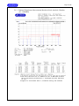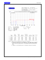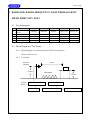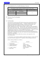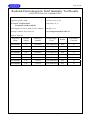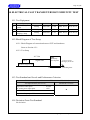
1
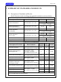
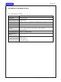
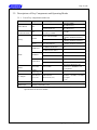
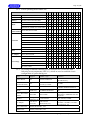
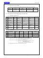
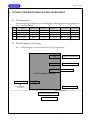
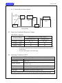
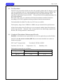
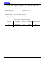
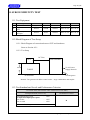
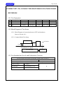
Page 1 of 69
CERTIFICATE OF CONFORMITY
For the following information
Product
Intel® Compute Stick
Test Model
STCK1A32WFC
Family Product Code
xSTCK1xFCx
Ref. File No.: C1M1503003
(Where x may be a combination of alphanumeric characters or
blank)
Brand Name
Intel®
Applicant
INTEL CORP.
Test Report Number
EM-E150125
Standards
EN 55022:2010 +AC: 2011, Class B
EN 61000-3-2:2014 and EN 61000-3-3:2008
EN 55024:2010
(EN 61000-4-2:2009, IEC 61000-4-2:Ed. 2.0:2008,
EN 61000-4-3:2006+A1:2008 +A2:2010,
IEC 61000-4-3 Ed.3.2:2010,
EN 61000-4-4:2012, IEC 61000-4-4 Ed. 3.0:2012
EN 61000-4-5:2006, IEC 61000-4-5 Ed. 2.0:2005,
EN 61000-4-6:2014, IEC 61000-4-6 Ed. 4.0:2013,
EN 61000-4-8: 2010, IEC 61000-4-8 Ed. 2.0:2009
EN 61000-4-11:2004, IEC 61000-4-11 Ed. 2.0:2004)
We hereby certify that the above product has been tested by us with the listed
standards and found in compliance with the council EMC directive 2004/108/EC.
The test data and results are issued on the EMC test report no. EM-E150125.
Signature
Allen Wang/Assistant General Manager
Date: 2015. 03. 17.
NVLAP Lab Code 200077-0
Test Laboratory:
AUDIX Technology Corporation, EMC Department
NVLAP Lab. Code: 200077-0
TAF Accreditation No.: 1724
FCC OET Designation: TW1004
Web Site: www.audixtech.com
The statement is based on a single evaluation of one sample of the above-mentioned products. It does not imply an
assessment of the whole production and does not permit the use of the test lab logo.
Page 2 of 69
EMC TEST REPORT
for
INTEL CORP.
Intel® Compute Stick
Test Model: STCK1A32WFC
Family Product Code: xSTCK1xFCx
(Where x may be a combination of alphanumeric characters or blank)
Brand: Intel®
Prepared for : INTEL CORP.
HF3-96, 5200 NE ELAM YOUNG PKY,
HILLSBORO, OR 97124 USA
Prepared by : AUDIX Technology Corporation
EMC Department
No. 53-11, Dingfu, Linkou Dist.,
New Taipei City 244, Taiwan
Tel: (02) 2609-9301, 2609-2133
Fax: (02) 2609-9303
File Number
Report Number
Date of Test
Date of Report
:
:
:
:
C1M1503003
EM-E150125
2015. 03. 04 ~ 16
2015. 03. 17
AUDIX Technology Corporation
Report No.: EM-E150125
Page 3 of 69
TABLE OF CONTENTS
Description
Page
EMC Test Report .............................................................................................................................6
1. DESCRIPTION OF VERSION .............................................................................................. 7 2. SUMMARY OF STANDARDS AND RESULTS .................................................................. 8 2.1. Description of Standards and Results .............................................................................................. 8 2.2. Description of Performance Criteria ................................................................................................ 9 3. GENERAL INFORMATION ............................................................................................... 10 3.1. Description of EUT ........................................................................................................................ 10 3.2. Descriptions of Key Components and Operating Modes ............................................................... 11 3.3. Description of Tested Supporting Unit and Cable.......................................................................... 13 3.4. Description of Test Facility ............................................................................................................ 14 3.5. Measurement Uncertainty .............................................................................................................. 14 4. CONDUCTED DISTURBANCE MEASUREMENT ......................................................... 15 4.1. Test Equipment .............................................................................................................................. 15 4.2. Block Diagram of Test Setup ......................................................................................................... 15 4.3. Limits for Conducted Emission Voltage (EN 55022, Class B) ...................................................... 16 4.4. Operating Condition of EUT.......................................................................................................... 16 4.5. Test Procedure ................................................................................................................................ 17 4.6. Conducted Disturbance Measurement Results............................................................................... 17 5. RADIATED DISTURBANCE MEASUREMENT.............................................................. 20 5.1. Test Equipment .............................................................................................................................. 20 5.2. Block Diagram of Test Setup ......................................................................................................... 20 5.3. Limits for Radiated Disturbance .................................................................................................... 22 5.4. Operating Condition of EUT.......................................................................................................... 22 5.5. Test Procedure ................................................................................................................................ 22 5.6. Radiated Disturbance Measurement Results .................................................................................. 24 6. HARMONICS CURRENT MEASUREMENT ................................................................... 29 6.1. Test Equipment .............................................................................................................................. 29 6.2. Block Diagram of Test Setup ......................................................................................................... 29 6.3. Test Standard .................................................................................................................................. 29 6.4. Deviation From Test Standard........................................................................................................ 29 6.5. Limit for Harmonics Current (Class D Equipment) ....................................................................... 30 6.6. Operating Condition of EUT.......................................................................................................... 30 6.7. Test Procedure ................................................................................................................................ 30 6.8. Test Results .................................................................................................................................... 30 7. VOLTAGE FLUCTUATION AND FLICKER MEASUREMENT.................................. 33 7.1. Test Equipment .............................................................................................................................. 33 7.2. Block Diagram of Test Setup ......................................................................................................... 33 7.3. Test Standard .................................................................................................................................. 33 7.4. Deviation From Test Standard........................................................................................................ 33 7.5. Limit for Voltage Fluctuation and Flicker ...................................................................................... 34 7.6. Operating Condition of EUT.......................................................................................................... 34 7.7. Test Procedure ................................................................................................................................ 34 7.8. Test Results .................................................................................................................................... 34 8. ELECTROSTATIC DISCHARGE IMMUNITY TEST .................................................... 36 8.1. Test Equipment .............................................................................................................................. 36 8.2. Block Diagram of Test Setup ......................................................................................................... 36 8.3. Test Standard and Levels and Performance Criterion .................................................................... 36 8.4. Deviation From Test Standard........................................................................................................ 37 AUDIX Technology Corporation
Report No.: EM-E150125
Page 4 of 69
8.5. Test Procedure ................................................................................................................................ 37 8.6. Test Results .................................................................................................................................... 37 9. RADIATED, RADIO-FREQUENCY, ELECTROMAGNETIC FIELD IMMUNITY
TEST ........................................................................................................................................ 39 9.1. Test Equipment .............................................................................................................................. 39 9.2. Block Diagram of Test Setup ......................................................................................................... 39 9.3. Test Standard and Levels and Performance Criterion .................................................................... 40 9.4. Deviation From Test Standard........................................................................................................ 40 9.5. Test Procedure ................................................................................................................................ 40 9.6. Test Results .................................................................................................................................... 41 10. ELECTRICAL FAST TRANSIENT/BURST IMMUNITY TEST ................................. 43 10.1. Test Equipment .............................................................................................................................. 43 10.2. Block Diagram of Test Setup ......................................................................................................... 43 10.3. Test Standard and Levels and Performance Criterion .................................................................... 43 10.4. Deviation From Test Standard........................................................................................................ 43 10.5. Test Procedure ................................................................................................................................ 44 10.6. Test Results .................................................................................................................................... 44 11. SURGE IMMUNITY TEST ................................................................................................ 46 11.1. Test Equipment .............................................................................................................................. 46 11.2. Block Diagram of Test Setup ......................................................................................................... 46 11.3. Test Standard and Levels and Performance Criterion .................................................................... 46 11.4. Deviation From Test Standard........................................................................................................ 47 11.5. Test Procedure ................................................................................................................................ 47 11.6. Test Results .................................................................................................................................... 47 12. IMMUNITY TO CONDUCTED DISTURBANCES INDUCED BY RF FIELDS ........ 49 12.1. Test Equipment .............................................................................................................................. 49 12.2. Block Diagram of Test Setup ......................................................................................................... 49 12.3. Test Standard and Levels and Performance Criterion .................................................................... 49 12.4. Deviation From Test Standard........................................................................................................ 50 12.5. Test Procedure ................................................................................................................................ 50 12.6. Test Results .................................................................................................................................... 50 13. POWER FREQUENCY MAGNETIC FIELD IMMUNITY TEST ................................ 52 13.1. Test Equipment .............................................................................................................................. 52 13.2. Block Diagram of Test Setup ......................................................................................................... 52 13.3. Test Standard and Levels and Performance Criterion .................................................................... 52 13.4. Deviation From Test Standard........................................................................................................ 52 13.5. Test Procedure ................................................................................................................................ 53 13.6. Test Results .................................................................................................................................... 53 14. VOLTAGE DIPS/SHORT INTERRUPTIONS/VOLTAGE VARIATIONS
IMMUNITY TEST ................................................................................................................. 55 14.1. Test Equipment .............................................................................................................................. 55 14.2. Block Diagram of Test Setup ......................................................................................................... 55 14.3. Test Standard and Levels and Performance Criterion .................................................................... 55 14.4. Deviation From Test Standard........................................................................................................ 55 14.5. Test Procedure ................................................................................................................................ 56 14.6. Test Results .................................................................................................................................... 56 15. PHOTOGRAPHS ................................................................................................................. 58 15.1. Photos of Conducted Disturbance Measurement ........................................................................... 58 15.2. Photos of Radiated Disturbance Measurement at Semi-Anechoic Chamber (30-1000MHz) ........ 60 15.3. Photo of Radiated Disturbance Measurement at Semi-Anechoic Chamber (Above 1GHz) .......... 61 15.4. Photo of Harmonics Current Measurement.................................................................................... 62 15.5. Photo of Voltage Fluctuation and Flicks Measurement.................................................................. 62 15.6. Photos of Electrostatic Discharge Immunity Test .......................................................................... 63 15.7. Photos of Radiated, Radio-Frequency, Electromagnetic Field Immunity Test .............................. 66 15.8. Photos of Electrical Fast Transient/Burst Immunity Test ............................................................... 67 AUDIX Technology Corporation
Report No.: EM-E150125
Page 5 of 69
15.9. Photo of Surge Immunity Test ....................................................................................................... 67 15.10. Photos of Immunity to Conducted Disturbances Induced by RF Fields ..................................... 68 15.11. Photo of Power Frequency Magnetic Field Immunity Test ......................................................... 68 15.12. Photo of Voltage Dips/Short Interruptions/Voltage Variations Immunity Test............................... 69 APPENDIX (Photos of EUT)
AUDIX Technology Corporation
Report No.: EM-E150125
Page 6 of 69
EMC TEST REPORT
Applicant
:
EUT Description
:
(A) Test Model
:
(B) Family Product Code :
(C) Serial Number
(D) Brand Name
(E) Power Supply
(F) Test Voltage
:
:
:
:
INTEL CORP.
Intel® Compute Stick
STCK1A32WFC
xSTCK1xFCx
(Where x may be a combination of alphanumeric
characters or blank)
N/A
Intel®
DC 5V, 2A
AC 230V, 50Hz (Via AC Adapter)
Measurement Standard Used:
EN 55022:2010 +AC: 2011, Class B
EN 61000-3-2:2014 and EN 61000-3-3:2013
EN 55024:2010
(EN 61000-4-2:2009, IEC 61000-4-2:Ed. 2.0:2008,
EN 61000-4-3:2006 +A1:2008 +A2:2010, IEC 61000-4-3 Ed.3.2:2010,
EN 61000-4-4:2012, IEC 61000-4-4 Ed. 3.0:2012,
EN 61000-4-5:2006, IEC 61000-4-5 Ed. 2.0:2005,
EN 61000-4-6:2014, IEC 61000-4-6 Ed. 4.0:2013,
EN 61000-4-8: 2010, IEC 61000-4-8 Ed. 2.0:2009
EN 61000-4-11: 2004, IEC 61000-4-11 Ed. 2.0:2004)
The device described above was tested by AUDIX Technology Corporation to determine the
maximum emission levels emanating from the device, its ensured severity levels, and
performance criterion. This test report contains the measurement results, and AUDIX
Technology Corporation assumes full responsibility for the accuracy and completeness of
these measurements. Also, this report shows that the EUT is technically compliant with the
requirements of EN 55022, EN 61000-3-2, EN 61000-3-3 and EN 55024 standards.
This report applies to above tested sample only and shall not be reproduced in part without
written approval of AUDIX Technology Corporation.
Date of Test:
2015. 03. 04 ~ 16
Date of Report:
2015. 03. 17
Producer:
(Tina Huang/Administrator)
Signatory:
(Allen Wang/Assistant General Manager)
AUDIX Technology Corporation
Report No.: EM-E150125
Page 7 of 69
1. DESCRIPTION OF VERSION
Edition No. Date of Revision
0
2015. 03. 17
Revision Summary
Original Report.
AUDIX Technology Corporation
Report Number
EM-E150125
Report No.: EM-E150125
Page 8 of 69
2. SUMMARY OF STANDARDS AND RESULTS
2.1. Description of Standards and Results
The EUT has been tested according to the applicable standards as referenced below.
EMISSION
Description of Test Item
Standard
Conducted disturbance
EN 55022:2010 +AC: 2011
Conducted disturbance
(Telecommunication port)
EN 55022:2010 +AC: 2011
Radiated disturbance
(30-1000MHz)
EN 55022:2010 +AC: 2011
Limits
Results
Class B
PASS
Minimum passing margin is
13.69dB at 0.182MHz
Class B
N/A
Class B
PASS
Minimum passing margin is
4.28dB at 599.39MHz
Class B
PASS
Radiated disturbance
(Above 1GHz)
EN 55022:2010 +AC: 2011
Harmonic current emissions
EN 61000-3-2:2014
Class D
PASS
Voltage fluctuations & flicker
EN 61000-3-3:2013
Section 5
PASS
Minimum passing margin is
6.78dB at 1020.21MHz
IMMUNITY (EN 55024:2010)
Description of Test Item
Basic Standard
Standard EUT
Criteria Criteria
Results
Electrostatic discharge
EN 61000-4-2:2009/
IEC 61000-4-2:Ed. 2.0:2008,
B
A
PASS
Radiated, Radio-frequency,
electromagnetic file
EN 61000-4-3:2006
+A1:2008 +A2:2010/
IEC 61000-4-3 Ed.3.2:2010
A
A
PASS
Electrical fast transient/burst
EN 61000-4-4:2012/
IEC 61000-4-4 Ed. 3.0:2012
B
A
PASS
B
A
PASS
B
N/A
N/A
Surge (Input a.c. power ports)
EN 61000-4-5:2006/
Surge (Telecommunication ports) IEC 61000-4-5 Ed. 2.0:2005,
Immunity to conducted
disturbances, induced by
radio-frequency fields
EN 61000-4-6:2014/
IEC 61000-4-6 Ed. 4.0:2013
A
A
PASS
Power frequency magnetic field
EN 61000-4-8: 2010/
IEC 61000-4-8 Ed. 2.0:2009
A
A
PASS
B
A
PASS
C
A
PASS
C
A
PASS
Voltage dips, >95% reduction
Voltage dips, 30% reduction
Voltage interruptions
EN 61000-4-11: 2004/
IEC 61000-4-11 Ed. 2.0:2004
N/A is an abbreviation for Not Applicable.
AUDIX Technology Corporation
Report No.: EM-E150125
Page 9 of 69
2.2. Description of Performance Criteria
General Performance Criteria
Examples of functions defined by the manufacturer to be evaluated during testing include,
but are not limited to, the following:
─ essential operational modes and states;
─ tests of all peripheral access
(hard disks, floppy disks, printers, keyboard, mouse, etc.);
─ quality of software execution;
─ quality of data display and transmission;
─ quality of speech transmission.
2.2.1. Performance criterion A
During and after the test the EUT shall continue to operate as intended without
operator intervention. No degradation of performance or loss of function is
allowed below a minimum performance level specified by the manufacturer
when the EUT is used as intended. The performance level may be replaced by a
permissible loss of performance. If the minimum performance level or the
permissible performance loss is not specified by the manufacturer, then either of
these may be derived from the product description and documentation, and by
what the user may reasonably expect from the EUT if used as intended.
2.2.2. Performance criterion B
After the test, the EUT shall continue to operate as intended without operator
intervention. No degradation of performance or loss of function is allowed, after
the application of the phenomena below a performance level specified by the
manufacturer, when the EUT is used as intended. The performance level may be
replaced by a permissible loss of performance.
During the test, degradation of performance is allowed. However, no change of
operating state or stored data is allowed to persist after the test.
If the minimum performance level (or the permissible performance loss) is not
specified by the manufacturer, then either of these may be derived from the
product description and documentation, and by what the user may reasonably
expect from the EUT if used as intended.
2.2.3. Performance criterion C
During and after testing, a temporary loss of function is allowed, provided the
function is self-recoverable, or can be restored by the operation of the controls
or cycling of the power to the EUT by the user in accordance with the
manufacturer’s instructions.
AUDIX Technology Corporation
Report No.: EM-E150125
Page 10 of 69
3. GENERAL INFORMATION
3.1. Description of EUT
Product
Intel® Compute Stick
Test Model
STCK1A32WFC
Family Product Code
xSTCK1xFCx
(Where x may be a combination of alphanumeric characters or blank)
Serial Number
N/A
Brand Name
Intel®
Applicant
INTEL CORP.
HF3-96, 5200 NE ELAM YOUNG PKY, HILLSBORO,
OR 97124 USA
Power Supply Rating
Refer to AC adapter rating
Date of Receipt of
Sample
2015. 02. 26
HDMI Port *1
USB 2.0 Port *1
Interface Ports of EUT
Micro USB 2.0 *1
Micro SD Card Slot *1
AUDIX Technology Corporation
Report No.: EM-E150125
Page 11 of 69
3.2. Descriptions of Key Components and Operating Modes
3.2.1. List of key components under test
Item
Supplier
Model / Type
STCK1A32WFC-IS
Mother Board
Intel
STCK1A8LFC-IS
CPU
(Socket: BGA592)
Intel
Intel® Atom™ CPU
[email protected]
H5TC4G63AFR-PBA
HYNIX
Memory
H5TC2G63FFR
Micron
SAMSUNG
eMMC
TOSHIBA
KINGSTON
Wi-Fi +BT Combo
REALTEK
Module
MT41K128M16JT
Character
With 32G eMMC
and 2GB memory
With 8G Emmc
and 1GB memory
1.33 GHz
2GB
IC DDR3L SDRAM.256M*16
1GB
IC DDR3L SDRAM.128M*16
1GB
IC DDR3L SDRAM.128M*16
KLMBG4GEND-B031
32G
KLM8G1GEAC-B031
8G
THGBMBG8D4KBAIR
32G
THGBMBG6D1KBAIL
8G
EMMC32G-S100-WB9
32G
EMMC08G-S100
8G
RTL8723BS
802.11 b/g/n Wireless LAN
Bluetooth 2.1+EDR/BT4.0 for
BT peripherals
Antenna
Linking
T-543-8321061
Technology Inc.
PIFA Antenna, 2.95dBi
AC Adapter
Asian Power
Device Inc.
AC Input:
100-240V~, 50-60Hz, 0.4A Max.
DC Output:
5V, 2A
Micro USB Cable
Shielded, Detachable, 1.0m
HDMI Cable
Shielded, Detachable, 0.2m
WB-10G05R
(Wall-mount, 2C)
Remark: For a more detailed features description, please refer to the manufacturer’s
specifications or the user manual.
AUDIX Technology Corporation
Report No.: EM-E150125
Page 12 of 69
3.2.2. List of operating modes under test:
SKU #1 ~ 14
1
Mother Board Intel, STCK1A32WFC-IS
2
3
4
5
6
7
8
9 10 11 12 13 14
V V V V V V V V V V V V V V
CPU
Intel, Z3735F
V V V V V V V V V V V V V V
Memory
HYNIX, H5TC4G63AFR-PBA
V V V V V V V V V V V V V V
SAMSUNG, KLMBG4GEND-B031
V
TOSHIBA, THGBMBG8D4KBAIR
eMMC
V V V V V V V V V V V
V
KINGSTON, EMMC32G-S100-WB9
Wi-Fi +BT
REALTEK, RTL8723BS
Combo Module
V
V V V V V V V V V V V V V V
1920*1200 60Hz 32bit 200% Font Size V V V
1920*1080 60Hz 32bit 200% Font Size
V
1600*1200 60Hz 32bit 150% Font Size
Resolution
V V V V V
V
1400*1050 60Hz 32bit 150% Font Size
V
1280*1024 75Hz 32bit 125% Font Size
V
1024*768 75Hz 32bit 100% Font Size
V
800*600 75Hz 32bit 100% Font Size
with HDMI Cable
Cable
V
V V V V V V V V V
without HDMI Cable
AC Adapter
V V V V
V
Asian, WB-10G05R.
V V V V V V V V V V V V V V
AC 100V, 50Hz
V
AC 110V, 60Hz
Test Voltage
V V V V V V V V V V
AC 120V, 60Hz
V
AC 220V, 60Hz
V
AC 230V, 50Hz
V
3.2.3. According to radiated emission pre-test result, the EUT collocates with
following worst components (SKU #1), which are used to establish a basic
configuration of system during test:
Item
Supplier
Model / Type
Character
Mother Board
Intel
STCK1A32WFC-IS
With 32G eMMC
and 2GB memory
CPU
(Socket: BGA592)
Intel
Intel® Atom™ CPU
[email protected]
1.33 GHz
Memory
HYNIX
H5TC4G63AFR-PBA
2GB
IC DDR3L SDRAM.256M*16
eMMC
SAMSUNG
KLMBG4GEND-B031
32G
RTL8723BS
802.11 b/g/n Wireless LAN
Bluetooth 2.1+EDR/BT4.0 for BT
peripherals
Wi-Fi +BT Combo
REALTEK
Module
Antenna
Linking
T-543-8321061
Technology Inc.
AC Adapter
Asian Power
Device Inc.
Micro USB Cable
Shielded, Detachable, 1.0m
HDMI Cable
Shielded, Detachable, 0.2m
WB-10G05R
(Wall-mount, 2C)
PIFA Antenna, 2.95dBi
AC Input:
100-240V~, 50-60Hz, 0.4A Max.
DC Output: 5V, 2A
AUDIX Technology Corporation
Report No.: EM-E150125
Page 13 of 69
3.2.4. Description of Test Modes
The worst mode was reported for emission and immunity measurement.
Configuration
Mode
SKU #1
Memory
eMMC
Resolution
Test Voltage
HYNIX,
SAMSUNG,
1920*1200 60Hz
AC 230V, 50Hz
H5TC4G63AFR-PBA KLMBG4GEND-B031 32bit 200% Font Size
3.3. Description of Tested Supporting Unit and Cable
3.3.1. Support Peripheral Unit
No.
Product
Brand
Model No.
Serial No.
FCC ID
MY-0W217F-71619By DoC
058-1522-A01
CN-0PH5NY-74445By DoC
1CM-142L
A
USB Keyboard
DELL
SK-8175
B
LCD Monitor
DELL
U3011T
C
MICRO SD Card
Kingston
NSDC4/8GB
N/A
N/A
D
BT Mouse
Logitech
M-R0047-O
1443LZ0A1DDS
FCC ID:
JNZMR0047O
E
Notebook PC
Lenovo
TP00034A
895097
By DoC
F
Wireless Router
ASUS
RT-N53
N/A
FCC ID:
MSQ-RT-N53
Remarks
Provided by
LAB
Provided by
LAB
Provided by
LAB
Provided by
LAB
Provided by
LAB
Provided by
LAB
3.3.2. Cable Lists
No.
1
2
3
4
Note:
Descriptions
Qty.
Length (m)
Shielding
(Yes/No)
Cores (Qty.)
Remarks
USB Cable
1
1.8
Yes
0
Provided by LAB
HDMI Cable
1
0.2
Yes
0
Supplied by Client
Micro USB Cable
1
1.0
Yes
0
Supplied by Client
LAN Cable
1
10.0
No
0
Provided by LAB
1. Support Units B: Power Cord: Non-Shielded, Detachable, 1.8m
2. Support Unit E: AC Adapter: DVE, M/N DSA-12G-12 FUS 120120;
Power Cord: Non-Shielded, Detachable, 1.0m
3. Support Unit F: AC Adapter: Lenovo, M/N ADLX65NCT3A;
DC Power Cord: Non-Shielded, Undetachable, 1.8m,
Bonded a ferrite core
AC Power Cord: Non-Shielded, Detachable, 1.0m
4. The support units (E-F) are communicated partner system.
AUDIX Technology Corporation
Report No.: EM-E150125
Page 14 of 69
3.4. Description of Test Facility
Name of Firm
:
AUDIX Technology Corporation
EMC Department
No. 53-11, Dingfu, Linkou Dist.,
New Taipei City 244, Taiwan
Test Facility & Location
:
No. 7 Shielded Room &
No. 1 10m Semi-Anechoic Chamber &
Immunity Test Site
No. 53-11, Dingfu, Linkou Dist.,
New Taipei City 244, Taiwan
NVLAP Lab. Code
:
200077-0
TAF Accreditation No.
:
1724
3.5. Measurement Uncertainty
Test Item
Frequency Range
Uncertainty
Conduction Test
150kHz~30MHz
±3.5dB
Radiation Test
(Distance: 10m)
30MHz~1000MHz
±5.3dB
Radiation Test
(Distance: 3m)
1GHz ~ 6GHz
±4.8dB
80MHz~200MHz
±1.7dB
200MHz~1000MHz
±1.8dB
1GHz~6GHz
±1.7dB
Radiated, Radio-frequency,
Electromagnetic Field Test
Remark : Uncertainty = kuc(y)
AUDIX Technology Corporation
Report No.: EM-E150125
Page 15 of 69
4. CONDUCTED DISTURBANCE MEASUREMENT
4.1. Test Equipment
The following test equipment was used during the conducted disturbance measurement:
(No. 7 Shielded Room)
Item
Type
Manufacturer
Model No.
Serial No.
Cal. Date
1.
2.
Test Receiver
A.M.N.
R&S
R&S
ESCI
ESH2-Z5
101276
100366
2014. 04. 14
2014. 03. 11
3.
4.
L.I.S.N.
Pulse Limiter
Kyoritsu
R&S
KNW-407
ESH3-Z2
8-1539-3
101495
2015. 01. 22
2015. 01. 17
Cal. Due
2015. 04. 13
2015. 03. 10
2016. 01. 21
2016. 01. 16
4.2. Block Diagram of Test Setup
4.2.1. Block Diagram of connection between EUT and simulators
USB
HDMI
1
2
USB KEYBOARD (A)
LCD MONITOR (B)
MICRO SD MEMORY CARD (C)
Intel® Compute Stick (EUT)
AC ADAPTER
3
5V DC
AC POWER
SOURCE
BT MOUSE (D)
Partner System
WIRELESS ROUTER (E)
4
NOTEBOOK PC (F)
AUDIX Technology Corporation
Report No.: EM-E150125
Page 16 of 69
4.2.2. Shielded Room Setup Diagram
40cm
EUT
Peripherals
Test Receiver
80cm
Table
80 cm
Table
LISN
AMN
Ground Plane
4.3. Limits for Conducted Emission Voltage
(EN 55022, Class B)
Frequency Range
Maximum RF Line Voltage, dB(μV)
Quasi-Peak Level
Average Level
0.15MHz – 0.5MHz
66 – 56
56 – 46
0.5MHz – 5MHz
56
46
5MHz – 30MHz
60
50
Remark:
1. If the average limit is met when using a Quasi-Peak detector, the EUT shall
be deemed to meet both limits and measurement with the average detector
is unnecessary.
2. The lower limit applies at the band edges.
4.4. Operating Condition of EUT
EUT Exercise Program and Condition
Operating System
Windows 8.1
Test Program
EMC Test
Graphic Function
Display scrolling “H” pattern with respective resolution at
the same time.
WLAN Function
To transmit Data transfer to partner Notebook PC
BT Function
To transfer BT signal to Bluetooth mouse
Card reader
Read/Write operation to memory card
The other peripheral devices were driven and operated in turn during all testing.
AUDIX Technology Corporation
Report No.: EM-E150125
Page 17 of 69
4.5. Test Procedure
The EUT was put on table which was above the ground by 80cm and AC adapter’s power
cord was connected to the AC mains through an Artificial Mains Network (AMN). The
other peripheral devices power cord connected to the power mains through a line
impedance stabilization network (LISN). This provided a 50Ω coupling impedance for
the tested equipment.
Both sides of AC line were checked to find out the maximum conducted emission
according to EN 55022 regulations during conducted emission measurement.
The bandwidth of the R&S Test Receiver ESCI was set at 9kHz.
The frequency range from 0.15MHz to 30MHz was pre-scanned with a peak detector.
All the final readings from Test Receiver were measured with the Quasi-Peak detector
and Average detector. (Remark: If the Average limit is met when using a Quasi-Peak
detector, the Average detector is unnecessary)
4.6. Conducted Disturbance Measurement Results
PASSED. (All emissions not reported below are too low against the prescribed limits.)
The EUT with the worst test mode (SKU #1) was measured and the test results are
listed in next pages.
EUT: Intel® Compute Stick
Test Date: 2015. 03. 04
Test Model: STCK1A32WFC
Temperature: 21℃
Humidity: 62%
The details of test mode are as follows:
Configuration Mode
SKU #1
Reference Test Data No.
Neutral
Line
# 28
# 27
AUDIX Technology Corporation
Report No.: EM-E150125
Page 18 of 69
AUDIX Technology Corporation
Report No.: EM-E150125
Page 19 of 69
AUDIX Technology Corporation
Report No.: EM-E150125
Page 20 of 69
5. RADIATED DISTURBANCE MEASUREMENT
5.1. Test Equipment
The following test equipment was used during the radiated disturbance measurement:
5.1.1. For 30MHz~1000MHz Frequency (At No.1 10m Semi-Anechoic Chamber)
Cal. Date
Cal. Due
2014. 12. 23
2015. 03. 05
2015. 12. 22
2016. 03. 04
100922
187158
2014. 05. 06
2015. 03. 04
2015. 05. 05
2016. 03. 03
8447D
CBL6112D
2727A06166
33819
2015. 02. 05
2014. 04. 19
2016. 02. 04
2015. 04. 18
CBL6112D
33820
2014. 04. 19
2015. 04. 18
Item
Type
Manufacturer
Model No.
1.
2.
Spectrum Analyzer
Spectrum Analyzer
Agilent
Agilent
3.
4.
Test Receiver
Amplifier
R&S
Sonoma
ESCI7
310N
5.
6.
Amplifier
Bilog Antenna
HP
TESEQ
7.
Bilog Antenna
TESEQ
Serial No.
N9010A-503 MY52220119
N9010A-503 MY51250850
5.1.2. For Above 1GHz Frequency (At No.1 10m Semi-Anechoic Chamber)
Item
Type
Manufacturer Model No.
Serial No.
1. Spectrum Analyzer
Agilent
N9010A-526 MY51250943
2.
3.
Amplifier
Horn Antenna
Agilent
EMCO
8449B
3117
3008A02681
00114403
Cal. Date
2015. 02. 24
2014. 03. 27
2014. 03. 18
Cal. Due
2016. 02. 23
2015. 03. 26
2015. 03. 17
5.2. Block Diagram of Test Setup
5.2.1. Block Diagram of connection between EUT and simulators
Same as Section 4.2.1.
AUDIX Technology Corporation
Report No.: EM-E150125
Page 21 of 69
5.2.2. Semi-Anechoic Camber (10m) Setup Diagram for 30-1000MHz
ANTENNA TOWER
ANTENNA ELEVATION VARIES FROM 1 TO 4 METERS
10 METERS
EUT
PERIPHERALS
0.8 METER
TURN TABLE
GROUND PLANE
TEST RECEIVER
5.2.3. Semi-Anechoic Chamber (3m) Setup Diagram for Above 1GHz
ANTENNA TOWER
ANTENNA ELEVATION VARIES FROM 1 TO 4 METERS
3 METERS
EUT
PERIPHERALS
0.8 METER
ABSORBER
TURN TABLE
GROUND PLANE
TEST RECEIVER
AUDIX Technology Corporation
Report No.: EM-E150125
Page 22 of 69
5.3. Limits for Radiated Disturbance
(EN 55022, Class B)
5.3.1. Limit below 1GHz
Frequency
(MHz)
Distance
(Meters)
Quasi-Peak Limits
(dBμV/m)
30 ~ 230
10
30
230 ~ 1000
10
37
Note: (1) The tighter limit applies at the edge between two frequency bands.
(2) Distance refers to the distance in meters between the measuring instrument
antenna and the closed point of any part of the E.U.T.
5.3.2. Limit above 1GHz
Frequency
(GHz)
Distance
(Meters)
Average Limits
(dBμV/m)
Peak Limits
(dBμV/m)
1~3
3
50
70
3~6
3
54
74
Note: (1) The lower limit applies at the transition frequency.
(2) Distance refers to the distance in meters between the measuring instrument
antenna and the closed point of any part of the E.U.T.
5.4. Operating Condition of EUT
Same as conducted disturbance measurement which is listed in 4.4.
except the test set up replaced by section 5.2.
5.5. Test Procedure
5.5.1. For Frequency Range 30MHz-1000MHz, which was measuring at Semi-Anechoic
Chamber:
The EUT and its simulator were placed on a turn table which was 0.8 meter
above ground. The turn table rotated 360 degrees to determine the position of
the maximum emission level. EUT was set 10 meters away from the receiving
antenna which were mounted on an antenna tower. The antenna can move up
and down between 1 meter and 4 meters to find out the maximum emission level.
Broadband antennas (Bilog Antenna) were used as a receiving antenna. Both
horizontal and vertical polarization of the antenna was set on measurement. In
order to find the maximum emission, all of the interface cables were manipulated
according to EN 55022 requirements.
The bandwidth of the R & S Test Receiver ESCI7 was set at 120 kHz.
The frequency range from 30MHz to 1000MHz was checked with Peak detector
and all final readings of measurement were with Quasi-Peak detector at
Semi-Anechoic Chamber.
AUDIX Technology Corporation
Report No.: EM-E150125
Page 23 of 69
5.5.2. For Frequency Range Above 1GHz, which was measuring
at Semi-Anechoic Chamber:
The EUT and its simulators were placed on a turn table which was 0.8 meter
above ground. The portion of the test volume that was obstructed by absorber
placed on the floor (30cm maximum). The turn table rotated 360 degrees to
determine the position of the maximum emission level. EUT was set 3 meters
away from the receiving antenna which was mounted on an antenna tower.
The antenna moved up and down between 1 to 4 meters to find out the maximum
emission level. A calibrated Horn Antenna was used as a receiving antenna.
Both horizontal and vertical polarization of the antenna was set on measurement,
and both average and peak emission level were recorded form spectrum analyzer.
In order to find the maximum emission level, all the interface cables were
manipulated according to EN 55022 on radiated measurement.
The resolution bandwidth of the Agilent Spectrum Analyzer N9010A-526 was
set at 1MHz.
The frequency range above 1GHz was checked and all final readings of
measurement were with Peak and Average detector.
In chapter 7.6.6.1 the standard EN 55016-2-3:2010 requires to include the values
of w in the test report:
“w: The dimension of the line tangent to the EUT formed by θ3dB at the
measurement distance d. Equation (10) shall be used to calculate w for each
actual antenna and measurement distance used. The values of w hall be included
in the test report. This calculation may be based on the manufacturer-provided
receive-antenna beamwidth specifications:
w = 2 × d × tan (0,5 ×θ3dB)
Frequency
GHz
1.00
2.00
4.00
6.00
3117 Horn
d = 3m
θ3dB (min)
(˚)
88
68
70
52
w (min)
(m)
5.79
4.05
4.20
2.93
The values of w. are greater than chapter 7.6.6.1 of Table 3, the minimum
dimension of w. (Wmin) requirements.
AUDIX Technology Corporation
Report No.: EM-E150125
Page 24 of 69
5.6. Radiated Disturbance Measurement Results
PASSED. (All emissions not reported below are too low against the prescribed limits.)
For 30MHz~1000MHz frequency range:
The EUT with the worst test mode (SKU #1) was measured and the test results are
listed in section 5.6.1.
EUT: Intel® Compute Stick
Test Date: 2015. 03. 13
Test Model: STCK1A32WFC
Temperature: 19℃
Humidity: 52%
The details of test mode are as follows:
Configuration Mode
Reference Test Data No.
Horizontal
Vertical
#4
#3
SKU #1
For Above 1GHz frequency range:
The EUT with the worst test mode (SKU #1) was measured and the test results are
listed in section 5.6.2.
EUT: Intel® Compute Stick
Test Date: 2015. 03. 13
Test Model: STCK1A32WFC
Temperature: 19℃
Humidity: 52%
The details of test mode are as follows:
Configuration Mode
SKU #1
Reference Test Data No.
Horizontal
Vertical
#4
#3
AUDIX Technology Corporation
Report No.: EM-E150125
Page 25 of 69
5.6.1. Radiated Disturbance Measurement Results at Semi-Anechoic Chamber
(30 - 1000MHz)
*
3.The worst emission was 31.57dBuV/m at 601.33 MHz when antenna
was in horizontal polarization, 1.5m height and turn table was
at 110°.
4.Degree is calculated from 0° clockwise facing the antenna.
AUDIX Technology Corporation
Report No.: EM-E150125
Page 26 of 69
*
3. The worst emission was 32.72dBuV/m at 599.39MHz when antenna
was in vertical polarization, 2.0m height and turn table was at
260°.
4. Degree is calculated from 0° clockwise facing the antenna.
AUDIX Technology Corporation
Report No.: EM-E150125
Page 27 of 69
5.6.2. Radiated Disturbance Measurement Results at Semi-Anechoic Camber
(Above 1GHz)
AUDIX Technology Corporation
Report No.: EM-E150125
Page 28 of 69
AUDIX Technology Corporation
Report No.: EM-E150125
Page 29 of 69
6. HARMONICS CURRENT MEASUREMENT
6.1. Test Equipment
Item
1.
2.
3.
4.
Type
Manufacturer Model No.
AC Power Source
TESEQ
NSG 1007-45
Signal Conditioning
TESEQ
CCN 1000-3
Unit
Three Phase
TESEQ
INA 2197
Impedance Network
Profline AC
TESEQ
NSG 2200-3
Switching Unit
Serial No.
1248A04038
Cal. Date
Cal. Due
2014. 01. 17
2016. 01. 16
1234A03680
2014. 01. 17
2016. 01. 16
1234A03681
2014. 01. 17
2016. 01. 16
EK 22713
2014. 01. 17
2016. 01. 16
6.2. Block Diagram of Test Setup
6.2.1. Block Diagram of connection between EUT and simulators
Same as Section 4.2.1.
6.2.2. Test Setup
EUT
80cm
AC Line
TABLE
Three
Phase
Impedance
Network
To AC Power
Supply Network
Ground Plane
6.3. Test Standard
EN 61000-3-2:2014
6.4. Deviation From Test Standard
No deviation.
AUDIX Technology Corporation
Report No.: EM-E150125
Page 30 of 69
6.5. Limit for Harmonics Current (Class D Equipment)
Harmonic order
n
Maximum permissible
harmonic current per watt mA/W
Maximum permissible
harmonic current A
Odd Harmonics Only
3
5
7
9
11
13
15 ≤ n ≤ 39
3.4
1.9
1.0
0.5
0.35
0.30
3.85/n
2.30
1.14
0.77
0.40
0.33
0.21
0.15x15/n
No limits apply for equipment with an active input power up to and including 75W.
6.6. Operating Condition of EUT
Same as conducted emission measurement which is listed in 4.4.
except the test set up replaced by section 6.2.
6.7. Test Procedure
6.7.1. Apply a 230V/50Hz rated test voltage which shall be maintained within
±2.0% and the frequency within ±0.5% of the nominal value to EUT.
6.7.2. Let EUT work as stated and through Universal Power Analyzer to measure
the EUT to get the harmonic current for Odd & Even harmonics up to 40th.
6.8. Test Results
PASSED.
(Complied with Criterion D)
The EUT with the worst test mode (SKU #1) was measured and the test results are
listed in next pages.
AUDIX Technology Corporation
Report No.: EM-E150125
Page 31 of 69
AUDIX Technology Corporation
Report No.: EM-E150125
Page 32 of 69
AUDIX Technology Corporation
Report No.: EM-E150125
Page 33 of 69
7. VOLTAGE FLUCTUATION AND FLICKER MEASUREMENT
7.1. Test Equipment
Item
1.
2.
3.
4.
Type
Manufacturer Model No.
AC Power Source
TESEQ
NSG 1007-45
Signal Conditioning
TESEQ
CCN 1000-3
Unit
Three Phase
TESEQ
INA 2197
Impedance Network
Profline AC
TESEQ
NSG 2200-3
Switching Unit
Serial No.
1248A04038
Cal. Date
Cal. Due
2014. 01. 17
2016. 01. 16
1234A03680
2014. 01. 17
2016. 01. 16
1234A03681
2014. 01. 17
2016. 01. 16
EK 22713
2014. 01. 17
2016. 01. 16
7.2. Block Diagram of Test Setup
7.2.1. Block Diagram of connection between EUT and simulators
Same as Section 4.2.1.
7.2.2. Test Setup
EUT
80cm
AC Line
TABLE
Three
Phase
Impedance
Network
To AC Power
Supply Network
Ground Plane
7.3. Test Standard
EN 61000-3-3:2013
7.4. Deviation From Test Standard
No deviation.
AUDIX Technology Corporation
Report No.: EM-E150125
Page 34 of 69
7.5. Limit for Voltage Fluctuation and Flicker
Tested Items
Description
Limit
Pst
Short-term Flicker Indicator
≤ 1.0
Plt
Long-term Flicker Indicator
≤ 0.65
d(t)
Voltage change more than 500ms
≤ 3.3%
dc
Relative steady-state voltage change
≤ 3.3%
Maximum relative voltage change
≤ 4%
Maximum relative voltage change
≤ 6%
Maximum relative voltage change
≤ 7%
dmax
7.6. Operating Condition of EUT
Same as conducted emission measurement which is listed in 4.4.
except the test set up replaced by section 7.2.
7.7. Test Procedure
Apply a 230V/50Hz rated test voltage which shall be maintained within ±2.0% and
the frequency within ±0.5% of the nominal value to EUT.
7.8. Test Results
PASSED.
The EUT with the worst test mode (SKU #1) was measured and the test results are
listed in next page.
Remark: Due to the maximum r.m.s input current (including inrush current) does not
exceed 20A, and the supply current after inrush is within a variation band of 1.5A,
it’s not applicable to test the manual switching.
AUDIX Technology Corporation
Report No.: EM-E150125
Page 35 of 69
AUDIX Technology Corporation
Report No.: EM-E150125
Page 36 of 69
8. ELECTROSTATIC DISCHARGE IMMUNITY TEST
8.1. Test Equipment
Item
Type
1. ESD Simulator
Manufacturer
EM TEST
Model No.
dito
Serial No.
V0503100055
Cal. Date
2014. 04. 21
Cal. Due
2015. 04. 20
8.2. Block Diagram of Test Setup
8.2.1. Block Diagram of connection between EUT and simulators
Same as Section 4.2.1.
8.2.2. Test Setup
Vertical plate
EUT
Horizontal plate
Insulation
470kohm
470kohm
0.8M
470kohm
470kohm
Ground Plane
8.3. Test Standard and Levels and Performance Criterion
EN 55024:2010 (EN 61000-4-2:2009/IEC 61000-4-2 Ed 2.0:2008)
Test Specification (Test Level)
Performance Criteria
Contact Discharge
±2kV and ±4kV
Air Discharge
±2kV, ±4kV and ±8kV
AUDIX Technology Corporation
B
Report No.: EM-E150125
Page 37 of 69
8.4. Deviation From Test Standard
Contact Discharge mode level up to ±10 kV
Air Discharge mode level up to ±12kV
8.5. Test Procedure
8.5.1. Air Discharge
This test is done on a non-conductive surfaces. The round discharge tip of the
discharge electrode shall be approached as fast as possible to touch the EUT.
After each discharge, the ESD generator discharge electrode shall be removed
from the EUT. The generator is then retrigged for a new single discharge and
repeated 10 discharges each at positive and negative polarity for each preselected
test point. This procedure shall be repeated until all the air discharge
completed.
8.5.2. Contact Discharge
All the procedure shall be same as 8.5.1. except that the tip of the discharge
electrode shall touch the EUT conductive surfaces & repeated 25 discharges each
at positive and negative polarity for each test point before the discharge switch is
operated.
8.5.3. Indirect discharge for horizontal coupling plane
At least 25 discharges each at positive and negative polarity shall be applied to
the horizontal coupling plane, at points on each side of the EUT. The ESD
generator positions vertically at a distance of 0.1m from the EUT and with the
discharge electrode touching the coupling plane.
8.5.4. Indirect discharge for vertical coupling plane
At least 25 discharges each at positive and negative polarity shall be applied to
the center of one vertical edge of the coupling plane. The coupling plane, of
dimensions 0.5m x 0.5m, is placed parallel to, and positioned at a distance of
0.1m from the EUT. Discharges shall be applied to the coupling plane, with
this plane in sufficient different positions that the four faces of the EUT are
completely illuminated.
8.5.5. For above tests, the voltage was increased from the minimum to the selected test
level.
8.6. Test Results
PASSED.
(Complied with Criterion A).
The EUT with the worst test mode (SKU #1) was measured and the test results are
listed in next page.
AUDIX Technology Corporation
Report No.: EM-E150125
Page 38 of 69
Electrostatic Discharge Immunity Test Results
AUDIX TECHNOLOGY CORPORATION
Applicant: INTEL CORP.
Test Date: 2015. 03. 12
Atmospheric Pressure: 99kPa
EUT: Intel® Compute Stick,
Test Model: STCK1A32WFC
Temperature: 20 °C
Power Supply: AC 230V, 50Hz (Via AC Adapter)
Humidity: 50 %
Working Condition: See section 4.4.
Test Configuration Mode: SKU #1
Engineer: Jacky Chen
Air Discharge
Voltage kV Level / Discharge per polarity 10 / Result
Test Location
HDMI (1)
DC IN (2)
USB (3)
SD Card Slot (4)
LED (5)
Button(6)
Hole*4 (7 ~ 10)
Seam*7 (11 ~ 17)
+2
ND
ND
ND
ND
ND
ND
ND
ND
-2
ND
ND
ND
ND
ND
ND
ND
ND
+4
A
A
A
A
ND
A
A
ND
-4
A
A
A
A
ND
A
A
ND
+8 -8 +10 -10
A A A A
A A A A
A A A A
A A A A
A A A A
A A A A
A A A A
A A A A
+12
A
A
A
A
A
A
A
A
-12
A
A
A
A
A
A
A
A
Comments
Contact Discharge Voltage kV Level / Discharge per polarity 25 / Result
Test Location
+2 -2 +4 -4 +6 -6 +8 -8 +9 -9 +10 -10 Comments
Note
Indirect Contact
Voltage kV Level / Discharge per polarity 25 / Result
Test Location
VCP Front
VCP Right
VCP Left
VCP Back
HCP Bottom
Additional Notes
Measurement
Points
+2 -2 +4 -4 +6 -6 +8 -8 +9 -9 +10 -10
A A A A A A A A A A A A
A A A A A A A A A A A A
A A A A A A A A A A A A
A A A A A A A A A A A A
A A A A A A A A A A A A
Comments
Please refer to the Photos of ESD Test Points
ND=No Discharge; Meets criteria but unable to obtain an electrostatic discharge (ESD)
at this test point.
Note: Due to the EUT has no conductive surface. It’s not necessary to test contact discharge.
AUDIX Technology Corporation
Report No.: EM-E150125
Page 39 of 69
9. RADIATED, RADIO-FREQUENCY, ELECTROMAGNETIC
FIELD IMMUNITY TEST
9.1. Test Equipment
Item
1.
2.
3.
4.
5.
Type
Radiated Immunity
System
Power Amplifier
Power Meter
Power Antenna
Direction Coupler
Manufacturer
Model No.
Serial No.
Cal. Date
Cal. Due
TESEQ
ITS 6006
033009
2014. 10. 01
2015. 09. 30
T44214
073365
9128E084
98618
N.C.R.
2014. 10. 04
N.C.R.
2014. 08. 13
N.C.R.
2015. 10. 03
N.C.R.
2015. 08. 12
TESEQ
CBA 1G-275
TESEQ
PM 6006
Schwarzbeck STLP 9128 E
TESEQ
C5982-10
9.2. Block Diagram of Test Setup
9.2.1. Block Diagram of connection between EUT and simulators
Same as Section 4.2.1.
9.2.2. Test Setup
Anechoic
Chamber
3 Meters
EUT
1.55 Meter
ABSORBER
0.8 Meter
Control
Room
Direction Coupler
Power Amp.
Power Meter
Radiated Immunity System
AUDIX Technology Corporation
Personal Computer
Report No.: EM-E150125
Page 40 of 69
9.3. Test Standard and Levels and Performance Criterion
EN 55024:2010
(EN 61000-4-3: 2006+A1:2008+A2:2010/IEC 61000-4-3 Ed.3.2:2010)
Test Specification (Test Level)
Performance Criteria
Frequency Range
80-1000MHz
Field Strength
3V/m (unmodulated, r.m.s)
Modulation & Signal
80%, 1kHz
A
9.4. Deviation From Test Standard
No deviation.
9.5. Test Procedure
The field sensor is placed on the EUT table (0.8 meter above the ground) which is 3
meters away from the transmitting antenna. Through the signal generator, power
amplifier and transmitting antenna to produce a uniformity field strength (3V/m
measured by field sensor) around the EUT table from frequency range
80MHz-1000MHz and records the signal generator‘s output level at the same time for
whole measured frequency range. Then, put EUT and its simulators on the EUT turn
table and keep them 3 meter away from the transmitting antenna which is mounted on
an antenna tower and fixes at 1.55 meter height above the ground. Using the recorded
signal generator’s output level to measure the EUT from frequency range
80MHz-1000MHz and both horizontal & vertical polarization of antenna must be set
and measured. Each of the four sides of EUT must be faced this transmitting antenna
and measures individually.
In this report, chose the most sensible side to measure, that is right side to face
transmitting antenna.
A CCD camera was put inside the chamber and through its display to monitor the EUT
operational situation to judge the EUT Compliance criterion during measurement.
All the scanning conditions are as follows:
Condition of Test
-------------------------------------1. Field Strength
2. Amplitude Modulated
3. Scanning Frequency
4.
5.
The Rate of Sweep
Dwell Time
Remarks
---------------------------------3V/m
1kHz, 80%AM
80MHz – 1000MHz
Step Size 1% increments
0.0015 decade/s
3 Sec.
AUDIX Technology Corporation
Report No.: EM-E150125
Page 41 of 69
9.6. Test Results
PASSED.
(Complied with Criterion A)
The EUT with the worst test mode (SKU #1) was measured and the test results are
listed in next page.
AUDIX Technology Corporation
Report No.: EM-E150125
Page 42 of 69
Radiated Electromagnetic Field Immunity Test Results
AUDIX TECHNOLOGY CORPORATION
Applicant: INTEL CORP.
Test Date: 2015. 03. 09
EUT: Intel® Compute Stick,
Test Model: STCK1A32WFC
Temperature: 21 °C
Power Supply: AC 230V, 50Hz (Via AC Adapter) Humidity: 43 %
Working Condition: See section 4.4.
Test Configuration Mode: SKU #1
Engineer: Mike Yu
Frequency
Rang
Position
(Angle)
Polarity of
Antenna
Field Strength
(V/m)
Results
Performance
Criterion
80-1000MHz
0°
Horizontal
3V/m+Modulated
Pass
A
80-1000MHz
90°
Horizontal
3V/m+Modulated
Pass
A
80-1000MHz
180°
Horizontal
3V/m+Modulated
Pass
A
80-1000MHz
270°
Horizontal
3V/m+Modulated
Pass
A
80-1000MHz
0°
Vertical
3V/m+Modulated
Pass
A
80-1000MHz
90°
Vertical
3V/m+Modulated
Pass
A
80-1000MHz
180°
Vertical
3V/m+Modulated
Pass
A
80-1000MHz
270°
Vertical
3V/m+Modulated
Pass
A
AUDIX Technology Corporation
Report No.: EM-E150125
Page 43 of 69
10. ELECTRICAL FAST TRANSIENT/BURST IMMUNITY TEST
10.1.Test Equipment
Item
1.
2.
3.
Type
EMS Immunity Test
System
C.D.N.
Burst/EFT Dataline
Coupling Clamp
Manufacturer Model No. Serial No.
Cal. Date
Cal. Due
TESEQ
NSG 3060
1519
2014. 08. 13
2015. 08. 12
TESEQ
CDN 3063
2074
2014. 08. 13
2015. 08. 12
TESEQ
CDN 3425
1717
2014. 08. 13
2015. 08. 12
10.2.Block Diagram of Test Setup
10.2.1. Block Diagram of connection between EUT and simulators
Same as Section 6.2.1.
10.2.2. Test Setup
AC Line
EUT
Signal Line
EMS
Immunity
Test System
To AC Power
Supply Network
Insulation Support 0.1m
Grounding Plate
Ground Plane
10.3.Test Standard and Levels and Performance Criterion
EN 55024:2010 (EN 61000-4-4:2012/IEC 61000-4-4 Ed3.0:2012)
Test Specification (Test Level)
Signal and control ports
AC mains power input ports
:
:
Performance Criteria
±0.5kV
±1kV
B
Tr/Th : 5/50ns
Repetition frequency : 5kHz
10.4.Deviation From Test Standard
No deviation.
AUDIX Technology Corporation
Report No.: EM-E150125
Page 44 of 69
10.5.Test Procedure
The EUT and its simulators shall be placed 0.1m high above the ground reference plane
which was a minimum area 1m x 1m metallic sheet with 0.65mm minimum thickness.
This reference ground plane shall project beyond the EUT by at least 0.1m on all sides
and the minimum distance between EUT and all other conductive structure, except the
ground plane beneath the EUT, shall be more than 0.5m.
10.5.1. For input and output AC power ports:
The EUT was connected to the power mains by using a coupling device which
couples the EFT interference signal to AC power lines, and the length of the
power line between the coupling device and the EUT shall be 1m or less. Both
polarities of the test voltage should be applied during compliance test and the
duration of the test can‘t less than 1min.
10.5.2. For signal lines and control lines ports:
The interface cables‘ length is less than 3m, therefore, it’s unnecessary to
measure.
10.5.3. For DC input and DC output power ports:
No DC ports. It‘s unnecessary to measure.
10.6.Test Results
PASSED.
(Complied with Criterion A)
The EUT with the worst test mode (SKU #1) was measured and the test results are
listed in next page.
AUDIX Technology Corporation
Report No.: EM-E150125
Page 45 of 69
Electrical Fast Transient/Burst Immunity Test Results
AUDIX TECHNOLOGY CORPORATION
Applicant: INTEL CORP.
Test Date: 2015. 03. 09
EUT: Intel® Compute Stick,
Test Model: STCK1A32WFC
Temperature: 20 °C
Power Supply: AC 230V, 50Hz (Via AC Adapter) Humidity: 55 %
Working Condition: See section 4.4.
Test Configuration Mode: SKU #1
Engineer: Jason Chen
Inject Place: AC Main Power Supply Port
Inject Line
Test Voltage
Inject Time Inject Method Results & Criterion
L1
±0.5kV, ±1kV
60s
Direct
Pass, A
L2
±0.5kV, ±1kV
60s
Direct
Pass, A
L1, L2
±0.5kV, ±1kV
60s
Direct
Pass, A
AUDIX Technology Corporation
Report No.: EM-E150125
Page 46 of 69
11. SURGE IMMUNITY TEST
11.1.Test Equipment
Item
Type
1. Control Center
Manufacturer
Model No.
Serial No.
9506267
Cal. Date
N.C.R.
Cal. Due
N.C.R.
Keytek
E103
2.
Surge Combination
Wave
Thermo
E501B
1003193
2015. 02. 24
2016. 02. 23
3.
Surge Coupler /
Decoupler
Thermo
E4551
1003195
2015. 02. 24
2016. 02. 23
11.2.Block Diagram of Test Setup
11.2.1. Block Diagram of connection between EUT and simulators
Same as Section 4.2.1.
11.2.2. Test Setup
EUT
AC Line
Test Generator
To AC Power
Supply Network
80cm
TABLE
Grounding Plate
Ground Plane
Remark: Test generator includes control center、surge combination and coupler.
11.3.Test Standard and Levels and Performance Criterion
EN 55024:2010 (EN 61000-4-5/IEC 61000-4-5 Ed. 2.0:2005)
Test Specification (Test Level)
Telecommunication ports
AC input and output power ports
--line to line
--line to earth
Performance Criteria
:
±1kV
:
:
±1kV
±2kV
B
Tr/Th : 1.2/50 (8/20) μs
AUDIX Technology Corporation
Report No.: EM-E150125
Page 47 of 69
11.4.Deviation From Test Standard
No deviation.
11.5.Test Procedure
11.5.1. Set up the EUT and test generator as shown on section 11.2.
11.5.2. For line to line coupling mode, provided a 0.5/1kV 1.2/50 μs current surge
(at open-circuit condition) and 8/20 μs current surge to EUT selected points.
11.5.3. At least 5 positive and 5 negative (polarity) tests with a maximum 1 pulse/min
repetition rate were conducted during test.
11.5.4. Different phase angles were done individually.
11.5.5. Repeat procedure 11.5.2. to 11.5.4. except the open-circuit test voltages
0.5kV/1kV/2kV for line to earth coupling mode test.
11.5.6. Record the EUT operating situation during compliance test and decide the EUT
immunity criterion for above each test.
11.6.Test Results
PASSED.
(Complied with Criterion A).
The EUT with the worst test mode (SKU #1) was measured and the test results are
listed in next page.
AUDIX Technology Corporation
Report No.: EM-E150125
Page 48 of 69
Surge Immunity Test Results
AUDIX TECHNOLOGY CORPORATION
Applicant: INTEL CORP.
Test Date: 2015. 03. 09
EUT: Intel® Compute Stick,
Test Model: STCK1A32WFC
Temperature: 20 °C
Power Supply: AC 230V, 50Hz (Via AC Adapter) Humidity: 55 %
Working Condition: See section 4.4.
Test Configuration Mode: SKU #1
Engineer: Jason Chen
Input And Output AC Power Port
Location Polarity
L-N
+
L-N
-
Phase Angle
0, 90, 180, 270°
No of
Pulse
Pulse Voltage
Results & Criterion
5
±0.5kV; ±1kV
Pass, A
5
±0.5kV; ±1kV
Pass, A
AUDIX Technology Corporation
Report No.: EM-E150125
Page 49 of 69
12. IMMUNITY TO CONDUCTED DISTURBANCES INDUCED BY
RF FIELDS
12.1.Test Equipment
Item
Type
1. RF Generator
2. 6dB Attenuator
3. CDN
Manufacturer
TESEQ
Model No.
NSG 4070B-30
Serial No.
035076
TESEQ
ATN 6050
38424
TESEQ
CDN M016
34607
Cal. Date
Cal. Due
2014. 11. 05
2015. 03. 09
2014. 11. 05
2015. 11. 04
2016. 03. 08
2015. 11. 04
12.2.Block Diagram of Test Setup
12.2.1. Block Diagram of connection between EUT and simulators
Same as Section 4.2.1.
12.2.2. Common Mode Test Setup
EUT
CDN
AC Source
0.1m
Ground Reference support
RF Generator
Attenuator
12.3.Test Standard and Levels and Performance Criterion
EN 55024:2010 (EN 61000-4-6:2014/IEC 61000-4-6 Ed. 4.0:2013)
Test Specification (Test Level)
Performance Criteria
Signal and telecommunication ports, AC Input and Output Power Ports
Frequency Range
0.15-80MHz
Field Strength
3V (unmodulated, r.m.s)
Modulation
80% AM (1kHz)
AUDIX Technology Corporation
A
Report No.: EM-E150125
Page 50 of 69
12.4.Deviation From Test Standard
No deviation.
12.5.Test Procedure
12.5.1. Set up the EUT, CDN and test generators as shown on section 12.2.
12.5.2. The EUT and supporting equipment were placed on an insulating support 0.1m
high above a ground reference plane. CDN (coupling and decoupling device)
was placed on the ground plane making contact with it at about 0.1-0.3m from
EUT. Cables between CDN and EUT were as short as possible.
12.5.3. The disturbance signal described below was injected to EUT through CDN.
12.5.4. The EUT operates within its operational mode(s) under intended climatic
conditions after power on.
12.5.5. The frequency range was swept from 0.15 to 80MHz using 3V signal level, and
with the disturbance signal 80% amplitude modulated with a 1kHz sine wave.
12.5.6. The rate of sweep shall not exceed 1.5*10^3decades/s. Where the frequency was
swept incrementally, the step size shall not exceed 1% of the start and thereafter
1% of the preceding frequency value.
12.5.7. Recording the EUT operating situation during compliance testing and decide the
EUT immunity criterion.
12.6.Test Results
PASSED.
(Complied with Criterion A)
The EUT with the worst test mode (SKU #1) was measured and the test results are
listed in next page.
AUDIX Technology Corporation
Report No.: EM-E150125
Page 51 of 69
Immunity to Conducted Disturbances Induced by RF Fields
Test Results
AUDIX TECHNOLOGY CORPORATION
Applicant: INTEL CORP.
Test Date: 2015. 03. 16
EUT: Intel® Compute Stick,
Test Model: STCK1A32WFC
Temperature: 20 °C
Power Supply: AC 230V, 50Hz (Via AC Adapter) Humidity: 52 %
Working Condition: See section 4.4.
Test Configuration Mode: SKU #1
Engineer: Xar Xhuo
Frequency Rang
Injected Position
Field Strength
(V/m)
Results
Performance
Criterion
0.15-80MHz
Main Port
(AC Power Line)
3V/m+Modulated
Pass
A
Modulation Signal : 1kHz 80% AM.
AUDIX Technology Corporation
Report No.: EM-E150125
Page 52 of 69
13. POWER FREQUENCY MAGNETIC FIELD IMMUNITY TEST
13.1.Test Equipment
Item
1.
Type
Magnetic Field
Generator
Manufacturer
Model No.
Serial No.
Cal. Date
Cal. Due
Haefely Trench
MAG100.1
080015-01
2014. 05. 15
2015. 05. 14
13.2.Block Diagram of Test Setup
13.2.1. Block Diagram of connection between EUT and simulators
Same as Section 4.2.1.
13.2.2. Test Setup
INDUCTION
EUT
Magnetic Field
Generator
Non-Conductive Tab
13.3.Test Standard and Levels and Performance Criterion
EN 55024:2010 (EN 61000-4-8:2010/IEC 61000-4-8 Ed. 2.0:2009)
Test Specification (Test Level)
Performance Criteria
Power Frequency
50Hz or 60Hz
Magnetic Field Strength
1A/m (rms)
A
13.4.Deviation From Test Standard
No deviation.
AUDIX Technology Corporation
Report No.: EM-E150125
Page 53 of 69
13.5.Test Procedure
The EUT was placed on 0.8m high table. And subjected to the test magnetic field by
using the induction coil of standard dimensions (1m x 1m). The induction coil rotated by
90 degrees in order to expose the EUT to the test field with different orientations.
All cables of EUT exposed to magnetic field for 1m of their length
13.6.Test Results
PASSED.
(Complied with Criterion A)
The EUT with the worst test mode (SKU #1) was measured and the test results are
listed in next page.
AUDIX Technology Corporation
Report No.: EM-E150125
Page 54 of 69
Power Frequency Magnetic Field Immunity Test Results
AUDIX TECHNOLOGY CORPORATION
Applicant: INTEL CORP.
Test Date: 2015. 03. 11
EUT: Intel® Compute Stick,
Test Model: STCK1A32WFC
Temperature: 23 °C
Power Supply: AC 230V, 50Hz (Via AC Adapter) Humidity: 47 %
Working Condition: See section 4.4.
Test Configuration Mode: SKU #1
Engineer: Sam Yen
Power
Frequency
Magnetic Field
Coil
Orientation
Testing
Duration
Results
Performance
Criterion
50Hz
1A/m
X-axis
1 Min
Pass
A
50Hz
1A/m
Y-axis
1 Min
Pass
A
50Hz
1A/m
Z-axis
1 Min
Pass
A
AUDIX Technology Corporation
Report No.: EM-E150125
Page 55 of 69
14. VOLTAGE DIPS/SHORT INTERRUPTIONS/VOLTAGE
VARIATIONS IMMUNITY TEST
14.1.Test Equipment
Item
1.
Type
Manufacturer
Model No.
Serial No.
Cal. Date
Cal. Due
Chroma
6590
65900086
2014. 07. 18
2015. 07. 17
Power Source
14.2.Block Diagram of Test Setup
14.2.1. Block Diagram of connection between EUT and simulators
Same as Section 6.2.1.
14.2.2. Test Setup
O/P
I/P
AC Line
EUT
Power Source
TABLE
To AC Power Supply Network
14.3.Test Standard and Levels and Performance Criterion
EN 55024:2010 (EN 61000-4-11:2004/IEC 61000-4-11 Ed.2.0:2004)
Test Specification (Test Level)
Voltage dips
Voltage interruptions
Performance Criteria
>95% reduction, 0.5period
B
30% reduction , 25period
C
>95% reduction , 250period
C
14.4.Deviation From Test Standard
No deviation.
AUDIX Technology Corporation
Report No.: EM-E150125
Page 56 of 69
14.5.Test Procedure
14.5.1. Set up the EUT and test generator as shown on section 14.2.
14.5.2. The interruptions was introduced at selected phase angles with specified duration.
There was a 10s minimum interval between each test event.
14.5.3. After each test a full functional check was performed before the next test.
14.5.4. Repeat procedures 14.5.2 & 14.5.3 for voltage dips, only the test level and
duration was changed.
14.5.5. Record any degradation of performance.
14.6.Test Results
PASSED.
(Complied with Criterion C in Voltage Interruption &
Criterion A in Voltage Dips)
The EUT with the worst test mode (SKU #1) was measured and the test results are
listed in next page.
AUDIX Technology Corporation
Report No.: EM-E150125
Page 57 of 69
Voltage Dips/Short Interruptions/Voltage Variations
Immunity Test Results
AUDIX TECHNOLOGY CORPORATION
Applicant: INTEL CORP.
Test Date: 2015. 03. 11
EUT: Intel® Compute Stick,
Test Model: STCK1A32WFC
Temperature: 23 °C
Power Supply: AC 100 ~ 240V, 50/60Hz
(Via AC Adapter)
Humidity: 47 %
Working Condition: See section 4.4.
Test Configuration Mode: SKU #1
Engineer: Sam Yen
Single Test Voltage
Type of Test Test Voltage
Voltage Dips
Voltage
Interruptions
(1)100V
(2)240V
(1)100V
(2)240V
Phase Angle
Reduction
Period
Results &
Performance Criterion
0, 45, 90, 135, 180,
225, 270, 315°
>95%
0.5
Pass, A
0, 45, 90, 135, 180,
225, 270, 315°
30%
25
Pass, A
0, 45, 90, 135, 180,
225, 270, 315°
>95%
250
Pass C, Note
Note: Criteria C, The EUT was shut down during the test. It can be restored by the
operation of the controls by the user in accordance with the manufacturer’s instructions
after test.
AUDIX Technology Corporation
Report No.: EM-E150125
Page 58 of 69
15. PHOTOGRAPHS
15.1.Photos of Conducted Disturbance Measurement
FRONT VIEW OF CONDUCTED MEASUREMENT
BACK VIEW OF CONDUCTED MEASUREMENT
AUDIX Technology Corporation
Report No.: EM-E150125
Page 59 of 69
ZOOM-IN VIEW OF EUT
AUDIX Technology Corporation
Report No.: EM-E150125
Page 60 of 69
15.2.Photos of Radiated Disturbance Measurement at Semi-Anechoic Chamber
(30-1000MHz)
FRONT VIEW OF RADIATED MEASUREMENT
BACK VIEW OF RADIATED MEASUREMENT
AUDIX Technology Corporation
Report No.: EM-E150125
Page 61 of 69
15.3.Photo of Radiated Disturbance Measurement at Semi-Anechoic Chamber
(Above 1GHz)
FRONT VIEW OF RADIATED MEASUREMENT
BACK VIEW OF RADIATED MEASUREMENT
AUDIX Technology Corporation
Report No.: EM-E150125
Page 62 of 69
15.4.Photo of Harmonics Current Measurement
15.5.Photo of Voltage Fluctuation and Flicks Measurement
AUDIX Technology Corporation
Report No.: EM-E150125
Page 63 of 69
15.6.Photos of Electrostatic Discharge Immunity Test
For Air & Contact Discharge
AUDIX Technology Corporation
Report No.: EM-E150125
Page 64 of 69
For VCP Test
AUDIX Technology Corporation
Report No.: EM-E150125
Page 65 of 69
Photo of ESD Test Points
Photo of ESD Test Points
AUDIX Technology Corporation
Report No.: EM-E150125
Page 66 of 69
15.7.Photos of Radiated, Radio-Frequency, Electromagnetic Field Immunity Test
AUDIX Technology Corporation
Report No.: EM-E150125
Page 67 of 69
15.8.Photos of Electrical Fast Transient/Burst Immunity Test
15.9.Photo of Surge Immunity Test
AUDIX Technology Corporation
Report No.: EM-E150125
Page 68 of 69
15.10.Photos of Immunity to Conducted Disturbances Induced by RF Fields
15.11.Photo of Power Frequency Magnetic Field Immunity Test
AUDIX Technology Corporation
Report No.: EM-E150125
Page 69 of 69
15.12.Photo of Voltage Dips/Short Interruptions/Voltage Variations Immunity Test
PARTNER SYSTEM
AUDIX Technology Corporation
Report No.: EM-E150125