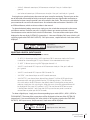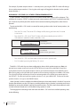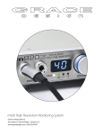
1
Owner’s manual Rev H main unit firmware Rev 1.08 RCU firmware Rev 1.07 all contents © Grace Design/ Lunatec LLC Welcome! Thanks for purchasing the Grace Design m906 high fidelity 5.1 monitoring system. We build all our products to be completely reliable and easy to use, so you can concentrate on producing great sounding audio, not struggling with complicated equipment or difficult to read product manuals. While the m906 has been designed to be straightforward to use, we do suggest that you spend a little time familiarizing yourself with the features and operational functions contained in this manual. Doing this now will likely make your experience with the m906 more enjoyable. In the event that you encounter any technical or operational difficulties with this or any Grace Design product, please feel free to contact us at 303-823-8100. Our office hours are from 9 to 5, Monday through Friday, MST. Or you can e-mail any questions to: [email protected] Also, please remember to visit our website - www.gracedesign.com for the latest Grace Design product information, owner’s manuals and technical documents. Grace Design has been building audiophile quality products for the recording industry for over a decade. The technology developed for the m906, and all of our products, has evolved through a process of extensive listening, field testing and meticulous refinement. Your new m906 system represents a combination of absolutely pristine audio performance, robust mechanical construction and bombproof reliability. Regardless of what type of work you do, your m906 will faithfully serve as an invisible link between your source audio and your speaker systems. We sincerely hope our products help you achieve a new level of excellence in your work! -The Grace Design Team Table of Contents Important Safety Information 3 m906 Key Features 4 m906 Audio Control Unit Front Panel 4 m906 Audio Control Unit rear panel 5 m906 Remote Control Unit 7 Unpacking and Installing your m906 9 Connecting the m906 10 System Connections 12 Operating the m906 14 Advanced Features: Accessing the Cal Modes 24 Cleaning and Maintenance 35 Cable and Connector Wiring Diagrams 36 Block Diagram 37 Specifications38 Warranty Information 40 Manual Revisions 41 2 grace design m906 owner’s manual Important Safety Information General • Indoor use only • Ordinary Protection: This equipment should not be exposed to dripping or splashing. • Avoid placing objects filled with liquids, such as vases or glasses, on this equipment. • Class I Equipment (grounded type) • Electrical rating: 100-120/220-240V~ 50-60Hz 25W • Mains supply voltage fluctuations are not to exceed ±10% of the nominal supply voltage. • Pollution Degree 2 • Installation (Overvoltage) Category II for transient overvoltages. • Maximum Relative Humidity: <80% • Operation temperature range: 10 °C to 40 °C • Storage and transportation temperature range –40 °C to 70 °C • Maximum altitude: 3000m (9843 ft) • Equipment suitable for continuous operation. • Weight: 14.1lbs / 6.4kg Safety Marking Symbols CAUTION: READ ACCOMPANYING DOCUMENTS This symbol, located on the equipment and in this manual, refers to important instructions. Read this manual thoroughly before operating this equipment. WARNING: ELECTRICAL SHOCK HAZARD This symbol, located on the equipment and in this manual, indicates the potential for electrical shock hazard. DC POWER OUTPUT This symbol, located on the equipment and in this manual, indicates a DC power output connection. Service Information The Grace Design m906 contains no user serviceable components. Contact Grace Design for repair and upgrade information. In the event that your Grace Design m906 needs to be returned to the factory, contact us for a return authorization number. grace design m906 owner’s manual 3 m906 Key Features • Multiple 5.1 and stereo analog inputs • 24-bit/192kHz digital 5.1 and stereo inputs – AES3, S/PDIF, ADAT and TOSLINK formats • s-Locktm PLL (Phase Lock Loop) for ultra-low jitter sample clock regeneration • Precision main and headphone level controls with a 100dB gain range in 0.5dB steps • All controls built into an elegant, compact desktop remote control unit • All I/O and audio are routed in a 2U, 19” rack mount Audio Control Unit with an external 1U, ½ rack linear power supply • Multiple speaker set selection – two surround/stereo sets and a third stereo set • High current reference headphone amplifier built in – one output on the remote control unit and an additional output on the Audio Control Unit • Comprehensive system level calibration (inputs, outputs, inter-channel balance, dim) • Individual channel solo/mute • Optional Downmix Module • Optional AES Loop-Thru feature • Balanced talkback microphone input with 48V phantom power with an activation switch on remote and an additional external switch control jack • Fixed level 5.1 DAC output for digital to analog transfers • 5 year limited warranty on parts and labor m906 Audio Control Unit Front Panel GRACE DESIGN USA headphone A power B A HEADPHONE OUTPUT The Audio Control Unit headphone output is provided via a ¼” TRS (Tip, Ring, Sleeve) jack. This output runs parallel with the headphone jack on the remote unit. B POWER LED The green POWER LED is illuminated when power is received from the external power supply to the rear panel mounted DC input. 4 grace design m906 owner’s manual m906 Audio Control Unit rear panel A C B F E D G H J I K M L N Left GRACE DESIGN USA PUSH 75 1M WORD CLOCK/ SUPERCLOCK DIGITAL INPUTS / SYNC GRACE DESIGN load 5.1 DAC OUT THRU IN ADAT 1 2 3 5.1 CR OUT 2 Right AT103 906 DAC 1 2 Center PUSH 5.1 INPUT 2 3 S/PDIF AES3 TOS DC IN AES3 x 4 PUSH PUSH TB MIC PUSH PUSH PUSH PUSH LS RS Sub 5.1 CR OUT 1 1 2 REMOTE TB SW L R L CR OUT 1 O P R CR OUT 2 Q L R CUE OUT R 1 2 3 L CUE IN S 1 2 3 3 R L 1 2 1 2 3 3 R L 2 CH 1 5.1 INPUT 1 1 2 3 R 2 CH 2 T U A 5.1 DAC OUTPUT This female DB-25 connector supplies 5.1 fixed level balanced DAC output sig- nals, wired to the Tascam DA-88 standard pinout. B 5.1 CR OUT #2 This female DB-25 connector carries the balanced analog Control Room Output #2 signals for connection to a 5.1 speaker system, wired to the Tascam DA-88 standard pinout. C 5.1 CR OUT #1 This female DB-25 connector carries the balanced analog Control Room Output #1 signals for connection to a 5.1 speaker system, wired to the Tascam DA-88 standard pinout. D DC IN This 6-pin male XLR DC input accepts the supplied cable from the m906’s external power supply. E WORD CLOCK/SUPER CLOCK THRU This BNC connector is used to pass an external Word Clock or Super Clock reference signal through to another digital device downstream of the m906. F WORD CLOCK/SUPER CLOCK IN This BNC connector allows the m906 to receive an external Word Clock or Super Clock source to be used as a reference for locking the m906’s internal clocks. G WORD CLOCK TERMINATION SWITCH This switch is used to properly terminate a connection from an external clock reference source to the m906 Word or Super Clock input. H ADAT INPUT This Lightpipe connector provides an 8-channel input from an ADAT format digital source. 44.1kHz and 48kHz sample rates are supported. I AES3 STEREO INPUT This female XLR connector is used to receive a stereo AES3 format digital signal. grace design m906 owner’s manual 5 J S/PDIF STEREO INPUT This RCA jack input accepts a S/PDIF format digital stereo signal. K TOSLINK STEREO INPUT This optical connector accepts a TOSLINK format digital stereo signal. L AES3 MULTI-CHANNEL INPUT This DB25 female connector accepts inputs from four AES3 format digital sources. The first three AES3 inputs serve as the 5.1 digital input source (channels 1 through 6) and the remaining pair is available as the second 2 CH AES3 input (channels 7 and 8). Wired to the Tascam DA-88 standard pinout. This connector also can provide four AES digital outputs with the AES Loop-Thru option. M TB MIC INPUT This female XLR connector connects a talkback microphone to the m906 for control room to studio communications. 48 Volt phantom power is provided. N 5.1 UNBALANCED ANALOG INPUTS These six RCA jacks are used to input an unbalanced (–10dBV) 5.1 source into the m906. O REMOTE CONNECTOR This female DB15 (high density) connector allows connection between the m906 Audio Control Unit and the remote control unit via the supplied remote cable. P TB SW JACK This ¼” TRS talkback switch jack is for connecting an external switch used to remotely activate the talkback microphone function. Q CR OUT 1 and CR OUT 2 Analog, balanced stereo outputs for stereo control room output sets #1 and #2. These connections are wired in parallel with the left and right outputs of the corresponding 5.1 DB-25 control room outputs. R CUE OUT LEFT AND RIGHT An analog balanced stereo output for the CUE input signal. The talk- back microphone signal is summed into this output. This output can also be configured to serve as a third stereo control room output pair. S CUE IN LEFT AND RIGHT This input is for connecting a stereo cue signal to the m906, which can be routed to the stereo cue outputs for studio talent monitoring and can be monitored directly in the control room. T 2 CH 1 and 2 CH 2 INPUT These are balanced analog stereo XLR inputs. U 5.1 BALANCED ANALOG INPUTS This DB25 female connector accepts analog balanced (+4dBu) signals for use as a 5.1 source input. 6 grace design m906 owner’s manual m906 Remote Control Unit Q R input analog A P 5.1 5.1 BAL UNBAL 2ch BAL1 2ch BAL2 cue input digital N B O M 5.1 AES3 5.1 ADAT 2ch AES3 2ch AES3 2ch S/PDIF 2ch sel ADAT/TOS mon cue cal (spkr 3) L channel solo/mute K C mono Left Center Right LS RS Sub dim mute J solo/mute 1 2 I spkr sel headphone level main level / edit talkback GRACE DESIGN USA D E F G H A INPUT ANALOG SWITCHES This row of five green LED illuminated switches is for selecting between and monitoring any of the analog sources connected to the m906. B INPUT DIGITAL SWITCHES This row of six green LED illuminated switches is for selecting between and monitoring any of the digital sources connected to the m906. C CHANNEL SOLO/MUTE SWITCHES These seven bi-colored switches are used to solo or mute any individual channel being monitored by the m906. The first six switches engage solo or mute for the relevant channel, while the solo/mute switch is used to toggle between solo or mute mode. Additionally, pressing and holding the MUTE/SOLO Button will toggle the m906’s optional DOWNMIX feature. D HEADPHONE LEVEL DISPLAY This blue, 3 digit headphone level display shows the current relative headphone output level value based on the position of the headphone level rotary encoder. The range of this display is 0 to 100dB. E HEADPHONE LEVEL ROTARY ENCODER This stepped rotary encoder controls the headphone out- put level in .5dB increments. When monitoring multichannel sources, pushing this encoder knob allows the headphone source channels to be selected. Additionally, double clicking the encoder alternately mutes or recalls the stored level preset. grace design m906 owner’s manual 7 F MAIN LEVEL/EDIT DISPLAY This blue, 3 digit main level/edit display shows the current relative main speaker output level values based on the position of the main level rotary encoder. The range of this display is 0 to 100dB. The display also shows edit values when the system is in CAL mode. G MAIN LEVEL/EDIT ROTARY ENCODER This stepped rotary encoder controls the main speaker output levels in .5dB increments. This encoder is also used to adjust level offset calibration values when in CAL mode. H TALKBACK SWITCH This red illuminated momentary action switch engages the talkback micro- phone circuit for as long as the switch is depressed. Releasing the switch disengages talkback. I SPKR SEL SWITCH The speaker select switch is used to toggle between the available speaker output sets. Each press of the switch lights the LED associated with each speaker set (1 or 2). J MONO SWITCH Pressing this green illuminated switch mono sums the stereo left and right chan- nels. K MUTE SWITCH The mute switch is used to fully mute all audio output from the m906. The red switch LED illuminates when active. L DIM SWITCH Pressing this illuminated switch reduces the monitoring level of the currently select- ed speaker output set by 20dB (this value can be edited in CAL mode). Pressing the switch again returns the system to its normal output monitoring levels. M CAL SWITCH Pressing the CAL switch activates calibration mode on the m906. When CAL mode is active, the red LED CAL switch will flash. CAL mode is exited by pressing the switch again. Please refer to the ‘Accessing the Cal Modes’ chapter of this manual for detailed information about m906 system calibration. N MON > CUE SWITCH The MON > CUE switch is an illuminated switch used for routing the selected stereo input source to the CUE output. In addition, this switch may be configured to access a third stereo speaker pair output. O SEL SWITCH The SEL switch is used to select between Word Clock or Super Clock when an external clock reference source is used. P SYSTEM LCD This backlit LCD shows various m906 status settings, such as the input source select- ed, current sample rate, s-Locktm state, clock source, etc… Q HEADPHONE AMPLIFIER JACK This ¼” TRS headphone output jack is provided on the remote con- trol unit to access the integrated reference headphone amplifier. R REMOTE CONNECTOR This female DB15 connector is used to supply the remote unit with power, headphone signal and serial communication. 8 grace design m906 owner’s manual Unpacking and Installing your m906 The m906 is shipped in two boxes. Box 1 contains: • the m906 Audio Control Unit • external power supply • AC power cord • 6-pin XLR DC power cable • small plastic bag containing four self-adhesive rubber feet • warranty registration card • some Grace Design literature for your reading pleasure Box 2 contains: • the remote control unit • 25’ remote cable • remote unit height/angle adjustment legs • small plastic bag containing four self-adhesive rubber feet OPEN AND INSPECT THE BOXES Open both shipping boxes, carefully remove the m906 system components and put them aside. Before you go any further, check to make sure the above listed components are included with your shipment. If you believe something is missing, contact your friendly Grace Design dealer and they will make sure you’re taken care of. SAVE YOUR BOXES!! We strongly encourage you to save all of the boxes and shipping materials supplied with your m906. They are specially designed to properly protect these valuable components, and in the unlikely event that you need to return them for service, only these OEM shipping materials can ensure their safe return to our factory. REGISTER YOUR UNIT Also, we strongly urge you to register your unit with Grace Design. We provide a limited 5 year warranty on all of our products, but if you don’t register your system it’s hard for us to help you if and when help becomes necessary. So please take a few minutes to complete the enclosed warranty registration card and mail it in, or simply go to the warranty registration form on our web site. Thank you! grace design m906 owner’s manual 9 Connecting the m906 Okay, let’s get started in making the necessary connections to get your m906 up and running. First thing to do is mount the Audio Control Unit in a rack. If you’re not rack mounting the unit, you should attach the supplied rubber feet on each corner of the chassis so you won’t scratch it or the surface you place it on. One important consideration is where to position the external power supply. The supplied cable to connect the power supply to the Audio Control Unit is 8’ (2.8m) long. The power supply can be mounted in a standard rack tray (not supplied) via the 10/32” mounting thread located towards the rear of the supply on the bottom panel. POWER CONNECTIONS The Disconnect Device for the m906 system is the Mains plug or the Appliance Coupler on the power supply cord. The Disconnect Device must remain accessible and operable. The power supply cord supplied with the m906 must be connected to a mains outlet with a protective earthing connection. Grounding Options In certain installations, it may be desirable to separate the m906’s signal ground from the power supply chassis and earth grounds. Noise inducing ground loops can be broken while retaining the safety feature of the grounded AC cable. The m906 should not be operated with a ground lift or “cheater” plug on the AC power cord. Simply set the AUDIO GND toggle switch on the rear panel of the power supply unit to the desired setting (ISO or EARTH). Check Line Voltage Settings The power supply unit has been set from the factory to operate at the voltage required for your part of the world. However, it’s important to double-check this in order to ensure no damage will come to the unit if power is applied while the setting is incorrect. Line Voltage Selector To change the line voltage, use a small screwdriver to pry open the voltage select door. Carefully remove the voltage select cam and re-insert it with the desired voltage showing. Use Table 1 below for voltage settings and fuse values. Table 1 Voltage and Fuse information CAM SETTING 100V~ 120V~ 220V~ 240V~ 240V~ 10 grace design m906 owner’s manual LINE VOLTAGE 100V~ 120V~ 220V~ 230V~ 240V~ FUSE VALUE 250V~ T 800mA L 250V~ T 800mA L 250V~ T 500mA L 250V~ T 500mA L 250V~ T 500mA L DC Power Cord The first connection to make is from the power supply unit to the main chassis with the supplied 6 pin XLR DC power cord. Important: the DC power cable and the remote cable should be connected BEFORE the AC power is turned on. This prevents incorrect power sequencing which can potentially cause damage to the m906’s audio circuits. Warning: A damaged DC power cord can create a shock hazard as Voltages of 72V DC can be present. Do not operate the m906 with a damaged DC power cord. Replace a damaged DC power cord with a replacement from Grace Design (WA047) only. AC Power Cord Now connect the supplied AC cord to the power supply and then to an AC outlet with the supplied AC cable. For safety, it is recommended that the cable be connected to a grounded outlet. Connecting the Remote Control Unit to the Audio Control Unit The m906 remote control unit connects to the Audio Control Unit via a supplied, high quality 25’ cable. Each end of the cable terminates in a male DB15 connector. This cable provides RS-422 serial data, power and headphone signal to the remote. Make the connection by securing the remote cable to the remote control unit and then attaching the other end to the Audio Control Unit. Both ends of the cable are identical so it doesn’t matter which end you connect to the remote or Audio Control Unit. Note: The HD15 connector on each end of the remote cable does not use a “VGA” computer monitor pinout (see the cable wiring diagram section of this manual). If you need a cable longer than 25 feet, an off-the-shelf VGA extension won’t work. Instead, please call us at 303-823-8100 and we’ll help you out. Tuning power on The power switch is located on the front panel of the Power Supply Unit. Switching the rocker position sets the switch to the I position turns the power on. Switching the rocker switch to the m906 in standby. Attaching the Tilt Adjustment Legs to the Remote Control Unit The m906 remote control unit can be placed directly on a flat surface or can be tilted forward with the pair of supplied legs. If you intend to place the remote on a flat surface, you should first attach the self-adhesive rubber feet (supplied) to each corner of the bottom of the chassis. This will prevent the unit from scratching your surface and from the bottom panel of the remote from being scratched. The legs for the remote are threaded on one end and screw into the threaded holes at the rear corners of the bottom panel. The remote tilt angle can be adjusted slightly by screwing the legs in or out. Power Sequence Before powering up your m906, make sure your powered monitors or power amps connected to grace design m906 owner’s manual 11 your monitors are turned OFF, which will prevent any “popping” in your speaker systems. Once the m906 and the rest of your audio system are powered up, turn on the power to your speakers. When powering down, we recommend that you first power off your speaker system and then power down the m906. It should also be noted that while the power sequence will not damage headphones connected to the m906, you should NOT be wearing them when power is applied or turned off. System Connections 5.1 DAC OUT The fixed level balanced DAC output connector is wired to the Tascam DA-88 standard. With CAL mode, the output level can be adjusted in 0.5dB steps. The factory default cal setting output Voltage is +16dBu for 0dBFS. 5.1 CR OUT 1 and 5.1 CR OUT 2 These are the multichannel control room outputs which are wired to the Tascam standard pinout and carry the balanced Left, Center, Right, Left Surround, Right Surround and Sub signals. The signal level on these connectors is controlled by the main level/edit encoder on the remote control. REMOTE CONNECTOR Connects the m906 main chassis unit to the remote control unit. This DB15 connector carries RS244 serial data, DC power and headphone signals. The m906 ships with a 25’ cable. While the serial data can travel several hundred feet we do not recommend cables longer than 50’ for headphone use. Be sure to use the supplied 15 pin cable and not an off the shelf computer video cable. If you need a longer cable contact your Grace Design dealer or call us directly. TB SW JACK The talkback switch input allows the connection of an external switch, such as a foot switch, for remotely activating the talkback mic input on the m906. The input is a TRS jack and is used with a “normally open” switching device. When using this jack, the talkback function can be activated at both the remote control unit and the external remote switch. DC IN This 6 pin XLR connector carries the DC power from the power supply unit. +24V, -24V, +8V and +48V are present. Connect this DC power cord BEFORE turning on the AC power at the power supply unit. CR OUT 1 and CR OUT 2 These are the stereo XLR balanced control room outputs. They are wired in parallel with the Left and Right signals from the corresponding 5.1 CR OUT #1 and #2 DB-25 connectors. Standard balanced XLR 12 grace design m906 owner’s manual cables can be used with these outputs (pin 1 shield, pin 2 positive, pin 3 negative). CUE OUT This is the stereo XLR balanced CUE output, which outputs the signal present on the CUE INPUT connectors. Typically this output would be wired to your studio’s headphone cue system or it can double as a third speaker output. Standard XLR balanced cables can be used with this output. 2 CH 1 and 2 CH 2 INPUTS These are stereo XLR balanced inputs. Standard XLR balanced cables can be used with these inputs (pin 1 shield, pin 2 positive, pin 3 negative). WORD CLOCK/SUPER CLOCK THRU This BNC connector allows you to pass the clock received at the Word Clock/Superclock input to other digital devices downstream of the m906. The output is buffered and is designed to drive a 75 Ohm line. WORD CLOCK/SUPER CLOCK IN The m906 can accept an external Word Clock or Super Clock signal from an external clock generating unit. This might be a stand-alone clock source or via, for example, the Word Clock output from your digital audio workstation. It should be noted that referencing the m906 from an external Word Clock is not necessary for the unit to function properly as the m906 will also function quite nicely by stripping embedded clock data from a connected digital audio source. However, you may have your entire digital audio system referenced from a single master clock that you feel particularly good about, hence the ability for the m906 to receive and lock itself to this clock. A high quality 75 Ohm cable should be used for word clock or Superclock connections. WORD CLOCK LOAD SWITCH The switch labeled 1M Ohm/75 Ohm is used to terminate the Word Clock input. If the Word Clock signal in your studio is being daisy-chained from unit to unit, (including the m906) you’ll want to set the switch to 1M Ohm, which is essentially an unloaded setting. If the m906 is the only device being clock referenced (or the last unit in a daisy-chain of other high impedance units), you’ll want to select the 75 Ohm load position. NOTE: Selecting the 75 Ohm load position when there is already another device on the line that has a 75 Ohm load will create a total load of 37 Ohms, which will attenuate the signal to a point where the m906 will not lock. ADAT INPUT This input accepts standard ADAT multi-channel optical cables (lightpipe). ADAT channel pair assignment is 1-2 Left-Right / 3-4 Left Surround-Right Surround / 5-6 Center-Sub / 7-8 left-right. AES3 INPUT This input conforms to the AES3 standard. Use of high quality 110 Ohm balanced cable is highly recommended. grace design m906 owner’s manual 13 S/PDIF INPUT This is a standard coaxial stereo digital input. The input impedance is 75 Ohms. Use a quality 75 Ohm cable for connections to this input. TOSLINK INPUT This is a standard stereo optical input connector for use with consumer devices. Standard TOSLINK optical cable can be used to connect to this input. AES3 x 4 INPUT This 8 channel input conforms to the AES3 standard. Channels 1-6 are used for surround monitoring while channels 7-8 can be monitored as a stereo signal. Use of high quality 110 Ohm balanced cable is highly recommended. Note: The m906 AES Loop-Thru option provides the user with four AES digital outputs via this multi-channel AES DB-25 connector. Each of the outputs is completely isolated and is designed to drive a 110-ohm termination. These are wired according to the TASCAM pinout as shown in the cable and connector diagram (pp. 36). TB MIC INPUT This is a standard microphone input. It can be used with dynamic or condenser microphones. Use CAL mode to turn the +48V phantom power on and off. 5.1 INPUT 2 These unbalanced input jacks are designed to interface with consumer DVD/SACD players. They accept a nominal –10dBV input level. 5.1 INPUT 1 This 5.1 channel input is wired to Tascam standard and accepts balanced +4dBu signals. Operating the m906 Okay, you’ve rack mounted your m906, attached the remote control unit, connected the power supply and have made all of your audio connections. Now the fun begins! The following sections will take you through the operational details of your m906 monitoring system. Selecting an Analog Input Source The m906 provides the following analog input sources: • 5.1 bal balanced 5.1 format input (DB25 connector wired to the Tascam standard pinout) • 5.1 unbal unbalanced 5.1 format input via RCA connectors. • 2ch bal 1 balanced stereo input (XLR connectors wired pin 2 hot, pin 3 cold and pin 1 ground) 14 grace design m906 owner’s manual • 2ch bal 2 balanced stereo input (XLR connectors wired pin 2 hot, pin 3 cold and pin 1 ground) • cue balanced stereo input (XLR connectors wired pin 2 hot, pin 3 cold and pin 1 ground) Pressing the cue switch activates the stereo cue input source for monitoring. The cue inputs on the rear of the m906 will normally be fed by a stereo pair output from your digital audio workstation or console that has been setup to provide a cue mix to talent in the studio. The cue input switch allows you to monitor this cue mix in the control room. Also related to the cue function is the MON > CUE and Talkback features, which are discussed later in the manual. To select the desired analog source input, simply press the switch that corresponds to the source you’d like to monitor. Each time you press a switch to select a new source to monitor, the new source becomes active and the source switch LED illuminates. The name of the current input will be displayed on line one of the SYSTEM LCD (screenshot 1). Line two will display DAC status (which is still supplying signal to the FIXED DAC OUTPUTS). DAC Input source, sample rate and s-Lock status will be displayed. screenshot 1 analog input selected, DAC status *indicates that s-Lock is active Selecting a Digital Input Source The m906 provides the following digital input sources: • 5.1 AES3 5.1 format input using 3 AES3 signals on a DB-25 connector wired to the Tascam standard for 8 channel digital I/O. Input channels 1-6 are monitored on this input. • 5.1 ADAT 5.1 format input using ADAT light pipe channels 1-6 • 2ch AES3 two channel AES3 input on an XLR connector wired pin 2 hot, pin 3 cold and pin 1 ground • 2ch AES3 two channel AES3 input on DB-25 channels 7-8 • 2ch S/PDIF two channel input on an RCA coaxial connector. • 2ch ADAT/TOS two channel input derived from channels 7-8 of the ADAT optical input connector or left and right channels from the TOSLINK optical input. (Out of the box, this switch selects the ADAT format as the default choice. To change the current source selection, simply press this switch again. When this occurs, the newly selected format will be displayed in the system LCD window.) NOTE: The two channel ADAT format source is derived from channels 7 and 8 from the ADAT input on the rear panel. It cannot be sourced from any other pair of ADAT channels. To select a digital input, simply press the corresponding input switch (AES3 1, AES3 2, S/PDIF or TOSLINK/ADAT ). The name of the current input will be displayed on line one of the SYSTEM LCD (screenshot 2). Line two will display DAC status (which is still supplying signal to the FIXED DAC OUTPUTS). DAC Input source, sample rate and s-Lock status will be displayed. screenshot 2 digital input select / DAC status grace design m906 owner’s manual 15 The TOSLINK/ADAT input switch functions as a toggle between either the TOSLINK or ADAT input. Pressing once activates the optical input that was last used. Pressing again will toggle to the other optical input. For example, say you were monitoring a TOSLINK signal and then switched to AES3 1, pressing the TOSLINK/ADAT switch would activate the TOSLINK input once again. To monitor the ADAT source, simply press the TOSLINK/ADAT switch again. NOTE: The digital ADAT input is derived from any one of the four channel pairs of an eight channel ADAT interface. The input pair is selected in CAL mode. To choose ADAT input pair do the following: 1. Press the CAL switch. The switch LED will begin to flash, letting you know that CAL mode is now active. 2. Press the optical input switch. The LCD display will indicate weather you are in TOSLINK or ADAT mode. If you are in TOSLINK input mode, press the optical input switch once again to reach ADAT mode. The menu is stepped as follows: TOSLINK INPUT OFFSET / ADAT INPUT OFFSET / ADAT SOURCE PAIR SELECT. 3. Once in ADAT INPUT OFFSET MODE, pressing the OPTICAL input switch one more time will bring up the ADAT SOURCE PAIR SELECT menu. Simply use the main/edit rotary encoder to choose the desired input source pair. 4. Press the CAL switch to exit CAL mode and return to normal operation. Changing the Clock Source The m906 DAC (Digital to Analog Converter) can be referenced to the embedded clock of a connected digital source such as AES3, ADAT, S/PDIF or TOSLINK. The DAC can also be clocked by an external Word Clock, Protools LOOP-SYNC Clock or Super Clock signal. The clock type you choose to use is entirely up to you. You may like a particular external Word Clock generating device that you reference your entire digital audio system to or you might feel completely comfortable with an embedded clock from a digital audio stream. From our point of view, it matters little as our s-Locktm PLL (Phase Lock Loop) will automatically be applied once it detects the incoming clock source. Read more about s-Locktm below. The SEL switch, located below the LCD window, is used to select the clock source you’d like to use as a reference for the m906 system. The LCD will show the currently selected source. If you’d like to change the current selection, repeatedly pressing the SEL switch will cycle you through the available choices which are: AES (AES) or ADAT (ADAT), WORDCLOCK (WORD), LOOP-SYNC (LOOP) and SUPERCLOCK (SUPC). The LCD text will flash if there is no valid clock available at the input selected. When the m906 has locked to the selected clock source the text in the LCD will be solid. The clock source preference for each digital input is saved in non volatile memory. To avoid inadvertent clock source changes, a clock select lockout feature is available in the CAL mode. When this feature is enabled, pressing the SEL button will not toggle the clock source, but instead will display “LOCKOUT!”. 16 grace design m906 owner’s manual About s-Locktm s-Lock is our new PLL circuitry that has been specifically developed for both the m906 and its stereo brother, the m904. The truly wonderful thing about s-Lock is that regardless of the condition of the external clock used as a reference for the m906, s-Lock will take this clock source and provide an extremely stable and ultra-low jitter clock to run the DACs without the use of sample rate convertion. Here’s a bit more detail on how this works: S-Lock is a crystal-based PLL used for regenerating the incoming digital clock. The crystals used have extremely low intrinsic jitter and are capable of locking to sample rates of up to 192kHz. When the digital input selected for the DAC is active, the s-Lock circuitry automatically captures the incoming recovered clock from AES3, S/PDIF, TOSLINK, or ADAT or from an external Word Clock or Super Clock. Once phase-lock with the incoming signal has been achieved, the DACs, which have been running off the original clock, are switched to run off the ultra-low jitter s-Lock system clock. If at any time s-Lock is lost or not achieved, the DACs are run off the original clock. The s-Lock system can effectively lock to input sample rates of 44.1kHz or 48kHz +/- 10Hz, 88.2kHz or 96kHz +/- 20Hz and 176.4kHz or 192kHz +/- 40Hz. If the incoming digital audio signal or word clock frequency is outside of these tolerances or if an invalid clock source is selected the s-Lock circuit will not lock and the s-Lock indicator on the system LCD not be visible. Even if the s-Lock does not achieve lock, the digital audio receiver circuits in the m906 can achieve excellent recovered clock jitter performance. Selecting Speaker Outputs The m906 provides the following speaker output sets: • 5.1 CR OUT 1 (balanced via female DB-25 connector) • 5.1 CR OUT 2 (balanced via female DB-25 connector) • Stereo CR OUT 1 (balanced via two male XLR connectors wired pin 2 hot, pin 3 cold and pin 1 ground) • Stereo CR OUT 2 (balanced via two male XLR connectors wired pin 2 hot, pin 3 cold and pin 1 ground) • Optionally, a third stereo pair via CUE OUT (balanced via two male XLR connectors wired pin 2 hot, pin 3 cold and pin 1 ground) The SPKR SEL switch, located directly above the TALKBACK switch, is used to cycle between available speaker output sets. The configuration of the speaker output set used is based on the current input selected, i.e. if you have a 5.1 input source selected, this audio will be routed out via one of the two available 5.1 control room outputs. If you have a stereo input source, this will be routed to the left and right Control Room output XLRs, as well as the left and right connections on a DB-25 Control Room output. Similarly, with a 5.1 source, left and right will be present on both the XLRs and the DB25s. The currently selected output set number is indicated by illuminating the relevant LED to the left of the SPKR SEL switch. To toggle through the available output sets, simply press the SPKR SEL switch. grace design m906 owner’s manual 17 For example, if speaker output number 1 is currently active, pressing the SPKR SEL switch will change this to speaker output number 2. Pressing the switch again will toggle the selection back to speaker output number 1. Using MON > CUE (spkr 3) as a Third Stereo Speaker Output In most situations, having access to two sets of stereo control room outputs will be adequate. This will allow, for instance, CR OUT 1 to feed your main stereo monitors and CR OUT 2 to feed a near-field pair. However, if you find yourself in need of a third stereo monitoring configuration, here’s how to proceed: To activate the MON > CUE switch as a control for routing audio to a third set of stereo speakers, do the following: • Press the CAL switch. The switch LED will begin to flash, letting you know that CAL mode is now active. • Press the MON > CUE switch. The LCD display will indicate whether you are in MON > CUE mode or in Speaker #3 mode (screenshots 3 & 4). screenshot 3 cue mode, global level screenshot 4 speaker 3 mode, global offset • Press the MON > CUE switch one more time to activate this special mode. • Exit CAL mode by pressing the flashing CAL switch. The MON > CUE switch has now been configured to select a third speaker output set. Note: the physical stereo outputs used for this are the CUE OUT XLRs on the rear of the m906 Audio Control Unit. Cycling between the first two speaker outputs is done as you would normally do, via the SPKR SEL switch. When you’re ready to select the third stereo speaker set for monitoring, simply press the MON > CUE switch. The switch LED will light solid and you’ll now be monitoring audio sent to a third stereo speaker pair via the CUE OUT’s. To return to the previous speaker selection (1 or 2), press MON>CUE. To return to the other speaker selection (1 or 2), press the SPKR SEL button. When Speaker 3 mode is enabled, the talkback feature on the remote control is disabled. Due to the fact that the talkback uses the CUE outputs, enabling talkback during Speaker 3 operation could cause feedback by routing the talkback signal to the control monitors. The rear panel remote talkback switch is under hardware control and is not disabled during Speaker 3 mode. To disengage this monitoring mode and return the MON > CUE switch to its default operating state, do the following: 18 grace design m906 owner’s manual 1. Press the CAL switch. 2. Press the MON > CUE switch. 3. Press the MON > CUE switch once more. 4. Exit CAL mode by pressing the flashing CAL switch. Using the MON > CUE Feature Normally, the CUE INPUT signal is routed to the CUE output. Pressing the MON > CUE switch when it’s controlling its default operational mode, i.e. has not been configured to operate as a third stereo speaker output as outlined above, routes the currently selected input source (L+R channels) that you’re monitoring to the CUE OUTs. This is particularly handy when you’d like to send the stereo source you’re monitoring in the control room out to the talent in the studio. Pressing the switch for the first time activates this mode and illuminates the switch LED. Pressing the switch again deactivates the MON > CUE feature and the switch LED extinguishes. Adjusting Main and Headphone Levels Both the main and headphone level rotary controls use stepped digital encoders that control analog circuitry in the m906. Both are attenuators, rather than gain controls. Using them is straightforward. To increase headphone or control room (main) monitoring levels, rotate the encoders in a clockwise fashion. To decrease levels, rotate the encoders in a counter-clockwise motion. Levels can be altered up or down in .5dB increments and channel tracking between channels is 0.05dB. In CAL mode (discussed later), the main level encoder is used to change parameters for the function currently being edited. Recalling the Main Output Level Preset To recall the stored level preset “double click” the MAIN level encoder switch by depressing it twice rapidly. This will restore the output to the saved preset level. This change will be reflected in the MAIN output level display. The MAIN output level preset can be set in CAL mode (discussed later). The Level Displays The large blue LED displays located to the left of the headphone and main level encoders show relative level values in dB. The range is 0 to 100 with 0 being full-off and 100 equaling unity gain, or full-on level. In CAL mode (discussed later), the LED display labeled main level/edit is used to display edit parameters as they’re being changed. Using the Headphone Outputs The m906 provides two reference headphone outputs, via ¼” TRS jacks wired as left channel to Tip, right channel to Ring and ground to Sleeve. One is located on the front panel of the Audio Control Unit and the other is on the rear of the remote control unit. Both may be used simultaneously. The m906 headphone amplifier is essentially the same technology as our m902 reference headphone amplifier. grace design m906 owner’s manual 19 Headphone Output MUTING / Recalling the Headphone Output Level Preset The HEADPHONE level encoder switch is used for two functions. The first of which is headphone output muting. When the headphone output is on (level is not set to 0.0) “double clicking” or depressing the switch twice rapidly will set the headphone output level to 0.0. This change will be reflected in the HEADPHONE output level display. The second function of the HEADPHONE encoder switch is to recall the stored headphone level preset. When the headphone output level is off (level set to 0.0) “double clicking” or depressing the switch twice rapidly will restore the output to the saved preset level. This change will be reflected in the HEADPHONE output level display. The HEADPHONE output level preset can be set in CAL mode (discussed later). Note: By setting the HEADPHONE output level preset at your normal listening level, the headphone output can be conveniently muted and restored very quickly. Using the Headphone Outputs to Monitor 5.1 Channels When you have a 5.1 source selected for monitoring, the headphone outputs will normally only allow you to hear the left and right channels from this 5.1 source. There may be times, however, when you may want to listen with headphones to other channel combinations of the 5.1 source. We’ve included a feature that allows you to do this. Here’s how this works: 1. First, select a 5.1 source input; analog or digital. Please note that this special 5.1 headphone mode cannot be made active if your current source selection is stereo. 2. Press down and hold the headphone level rotary encoder switch for about 4 seconds. This action will turn the 5.1 headphone feature on. 3. Notice that the Left and Right channel solo/mute switch LEDs are now illuminated. This indicates which pair of channels is currently being fed to the headphone outputs. You’ll also notice that the solo/mute master mode switch LED is extinguished. This is because this switch is not used in this mode. 4. The channel switches in this mode, unlike normal solo/mute mode, act in an interlocking fashion. This means that once you select a new pair of 5.1 channels to monitor through your headphones, the previous channel selections are automatically turned off. 5. Channel pairs that are available for monitoring in this mode include left/right, left surround/right surround and center/sub. Please note that you cannot monitor individual channels or other pair combinations other than which are listed above. 6. To select the Left Surround/Right Surround pair, press either the LS or RS switch. The surround channels will now be sent to the headphone outputs, the corresponding channel switch LEDs will light solid and the previous channel pair selection will become inactive. 7. To select the Center/Sub channel pair, press either the Center or Sub switch. These channels will now be sent to the headphone outputs, the corresponding channel switch LEDs will light solid and the previous channel pair selection will become inactive. 8. To return to the Left/Right channel pair, press either the Left or Right switch. These channels will now be sent to the headphone outputs, the corresponding channel switch 20 grace design m906 owner’s manual LEDs will light solid and the previous channel pair selection will become inactive. 9. To exit the 5.1 headphone mode and return to the m906’s normal operating state, press the headphone encoder switch. Note: If you’ve selected a 5.1 source, are currently in the 5.1 headphone mode and inadvertently select a stereo input source, this mode will automatically become inactive and the m906 will return to it’s normal operational state. You can, however, select different 5.1 sources while in this mode. CAL mode is not operable when this mode is active. Also, it should also be noted that this mode does NOT affect any of the 5.1 speaker output paths nor the fixed level DAC output. The Fixed Level 5.1 DAC Output The DACs in the m906 are reference quality circuits which are suitable for all critical monitoring, mixing and mastering applications. As a bonus feature, we’ve included a fixed level 5.1 DAC output that lets you access the DACs with a fixed output level. This is an extremely useful feature which allows you to, for instance, send out a 5.1 channel audio stream to a 6 channel recorder for mastering or archiving purposes. This output is fed from whatever you currently have selected as your digital input source. Another beautiful thing is that you can continue to monitor your control room source while a transfer from this output is being made. For instance, if you leave the current digital input to listen to an analog input, the previous digital input will continue to be sent to the fixed level DAC outputs. If you select a different digital source input, the fixed level DAC will then be fed from that new source. The lower line of the LCD display will indicate which digital input is active and its sample rate. The s-Lock status is indicated by the presence of an asterisk (*) to the right of the sample rate. The 5.1 DAC output level is set to 0dB as the default value on a new m906 system, but this can easily be changed in CAL mode (discussed later). Mono Mode Mono mode is used to sum the left and right channels of a stereo source to check for mono compatibility. This switch only affects the Left and Right channels of the control room outputs, but does provide a mono version of whatever inputs are selected in the headphone outputs. The mono mode switch is located immediately to the left of the dim switch. When pressed, mono mode becomes active and the switch LED lights solid. When pressed again, the mode is exited and the switch LED is extinguished. Dim Mode The dim switch, located to the right of the mono switch, is used to dim, or reduce, the control room output levels by a fixed dB amount. The default value for this is -20dB but this value can be changed in CAL mode (discussed below). Dim values can be set between -5 to -35 in 5dB steps. Dim will not affect the audio feed to the headphone outputs. When the dim switch is pressed, dim mode becomes active and the switch LED lights solid. When pressed again, dim is exited and the switch LED is extinguished. grace design m906 owner’s manual 21 Mute All Mode The mute switch is located to the immediate right of the dim switch. When this switch is pressed, all audio output is muted, or cut, from the control room monitors. Note that mute will not affect the audio feed to the headphone outputs. When the mute switch is pressed, mute mode becomes active and the switch LED lights solid. When pressed again, mute is exited and the switch LED is extinguished. DOWNMIX The m906 features an optional DOWNMIX module that creates a stereo L+R mix of a 6 channel surround source. All standard Dolby mix ratios can be calibrated by the user for both the center and surround channels. To toggle the DOWNMIX mode, press and hold the MUTE/SOLO button. Once enabled, the top line of the System LCD will display “DOWNMIX ACTIVE” (the display will toggle between this and the current input setup). Press and hold the MUTE/SOLO button again to exit DOWNMIX mode. Once DOWNMIX is enabled, the composite stereo mix is routed to the corresponding Left and Right control room outputs and the surround outputs are muted. Additionally, it is present as the Headphone Left and Right source and the MON->CUE source. NOTE: In a system without the DOWNMIX module installed, routing is unchanged when DOWNMIX is enabled and no composite mix is created. The DOWNMIX ratios are variable and adjusted in CAL mode (discussed in the ‘Advanced Features’ section of this manual). Channel Solo/Mute The m906 provides the ability to solo or mute any one channel or any combination of channels in either a stereo or 5.1 monitoring setup. Need to listen to the surround channels plus the center channel only? No problem. Wish you could mute the sub? You got it. Channel solo/mute mode is an easy way to accomplish these types of monitoring ta sks. The channel solo/mute function is provided via a row of seven bi-color, illuminated switches located directly below the input digital switch row on the remote control unit. Operating channel solo/mute is as follows: 1. First, select the mode of operation via the solo/mute switch. This switch is the last switch in the row and by default it will be lit green, which indicates that solo mode is currently active. If you’d like to change this to mute mode, simply press this switch and the switch led will light red, which now indicates that you’re in mute mode. 2. To select a channel to solo or mute, simply press the relevant channel switch. When you do this, the associated switch LED will light solid. Again, green shows solo while red indicates mute. These switches are additive, which simply means that you can add channels by pressing the relevant channel switches without disengaging the previous selections. For instance, if you’re in solo mode and want to solo the left surround channel, (LS) right surround (RS) and sub, you simply press each of these channels’ switches. If you set the solo/mute master mode switch to ‘mute’ at this point, these selected channels will be muted. 22 grace design m906 owner’s manual 3. To clear selected channels, simply press each of them again, which will also extinguish the switch LEDs. MUTE/SOLO Functionality with DOWNMIX When DOWNMIX mode is enabled, the SOLO/MUTE buttons function in an alternate fashion. This functionality is very useful for quickly referencing each surround channel’s contribution to a downmix. The LEFT, RIGHT and SUB MUTE/SOLO buttons are disabled when DOWNMIX is enabled and the LEFT and RIGHT channels are always ON. The SUB channel is always OFF. The CENTER, LS and RS MUTE/ SOLO buttons function as follows: 1. When SOLO mode is active, soloing a channel will cause non-soloed channels to be muted (not added to the downmix). 2. When MUTE mode is active, muting a channel removes it from the downmix. Using the Talkback Feature After you’ve plugged in a talkback mic, you can set the gain for the mic preamp, turn on 48V phantom power, if needed, and configure the talkback button for momentary or latching operation (each press toggles the talkback state). When you first power-up a new m906, the talkback mic preamp gain will be set to +30dB, 48V will be set to ‘off’ and the operation will be momentary. To change the gain 48V phantom and latch settings: 1. Press the CAL switch. The switch LED flashes, which indicates you’re now in CAL mode. 2. Press the TALKBACK switch. Once you do this, the main level/edit LED display will show the current mic amp gain level in dB and the LCD screen will read ‘set preamp gain’ (screenshot 5). screenshot 5 talkback mic amp gain setting 3. To increase the mic amp gain, rotate the main level encoder in a clockwise direction. As you do this, you’ll see the gain settings change. Preamp gain is adjustable from +30 to +70dB in 3dB steps. Rotate the encoder in a counter-clockwise direction to reduce the gain level. 4. If you’d like to change the state of 48V phantom power, press the TALKBACK switch again. The LED display now shows the on/off state of 48Vfor the preamp. Rotating the main level encoder to the right turns 48Von and rotating to the left turns it off (screenshot 6). screenshot 6 phantom power on/ off 5. If you’d like to change the talkback latch mode, press the TALKBACK switch again. The LED display now shows the on/off state of talkback latch feature. When the circle is on the grace design m906 owner’s manual 23 left of the edit window, the latch feature is disabled and the talkback button functions in momentary mode. When the circle is on the right side, the talkback button has a latching operation. Rotating the main level encoder counter-clockwise to disable the latching or clockwise to enable it. 6. When you’re done, press the CAL switch, which will exit CAL mode. Activating the talkback mic is be done by pressing the TALKBACK switch located on the remote control unit or remotely by using an external switch connected to the Audio Control Unit TB IN jack. The TALKBACK switch on the remote control unit operates in a momentary fashion, which activates the talkback circuit for as long as you hold the switch down. Releasing the TALKBACK switch ends talkback communications. The talkback signal is summed with the stereo signal that is fed out the CUE OUT connectors. When TALKBACK is engaged, the control room outputs are automatically dimmed. Additionally, the source feeding the CUE output will be automatically dimmed by the preset amount set in CAL mode (discussed later). NOTE: When Speaker 3 (spkr 3) mode is enabled, the talkback feature on the remote control is disabled. Due to the fact that the talkback uses the CUE outputs, enabling talkback during Speaker 3 operation could cause feedback by routing the talkback signal to the control monitors. The rear panel remote talkback switch is under hardware control and is not disabled during Speaker 3 mode. The LCD Window The LCD window (as highlighted throughout this manual), located in the upper right-hand corner of the remote unit, is used to display various system messages and text describing the current operating mode of the m906. It has been designed to provide you with a sharp, crisp display of vital system information in dimly lit environments and its off-axis viewing angle is superb. Typical LCD window showing the digital input selected and DAC status information input source selected s-Lock status word clock source sample rate Advanced Features: Accessing the Cal Modes The m906 includes a comprehensive set of calibration tools that allow you to tweak the operating parameters of your system. In normal day to day operation, you may not have a need to use the CAL modes much or you might regularly need to access a number of them for job specific tasks. In either case, these flexible tools provide an easy way for you to customize the settings of your m906. When CAL MODE is entered, the currently selected signal path is kept active until the user selects a different path for calibration. CAL values are stored in the non-volatile memory of your m906. 24 grace design m906 owner’s manual Whenever you edit a calibration value, the new value(s) instantly takes affect and are stored in this memory. Edited parameters are automatically recalled the next time you power up your system. System parameter values can also be reset to the factory defaults at any time via a sequence outlined at the end of this section. the following table shows the each user calibratable settings and its factory default setting. 1 2 3 4 5 6 7 8 9 10 11 12 13 14 15 16 17 18 19 feature Input source level offsets All Global Speaker Output Offsets Individual Speaker Output Offsets CUE Output Level CUE/Speaker 3 Mode / level Fixed DAC Output Level Main Output Level Preset Headphone Output Level Preset Headphone Gain DIM Level CUE Output DIM Level Lock Clock Select Talkback Latch Talkback Mic Preamp Gain Talkback Mic Phantom Power on/off 7-segment Brightness Control CENTER Channel DOWNMIX Ratio LEFT and RIGHT Surround channel DOWNMIX ratio Reset All System default settings factory setting 0dB 0dB 0dB 100dB CUE MODE / 0dB 0dB 0.0 0.0 0dB -20dB 0.0dB Disabled Disabled +30dB OFF 4 -3.0dB -6.0dB n/a Table 2 factory default CAL settings Calibrating Input Source Level offsets Every m906 source input, both analog and digital, can be calibrated to offset any level differences that may exist between different sources. The relative range of calibration is +/- 10dB in 0.5dB steps. To enter CAL mode and change the current input source level value, do the following: 1. Enter CAL mode by pressing the CAL switch. The switch LED will begin to flash, indicating that you’re now in calibration mode. All other switch LEDs on the remote control unit will be unlit. If you inadvertently entered CAL mode, simply press the CAL switch again. You’ll be returned to the normal operating state of the m906 and the CAL switch LED will extinguish. 2. Press the switch corresponding to the input source you’d like to calibrate. The switch LED will begin to flash and *input offset* will be displayed in the first line of the LCD screen (see screenshot 7). grace design m906 owner’s manual 25 screenshot 7 general input offset screen 3. “CAL” will be displayed in the headphone level LED display while the current input source offset level will be shown in the ‘main level/edit’ LED window . A value of “0” indicates that there is no offset level currently programmed. 4. Rotate the ‘main level/edit’ rotary encoder in a clockwise direction to increase the value of level offset. Rotate the encoder in a counter-clockwise motion to decrease the value. Note that these changes are reflected in real-time. 5. Once you’re satisfied with the new level offset value, you can select another input source for editing, select a new function to edit or exit CAL mode. 6. Exit CAL mode and return to the normal operating state by pressing the flashing CAL switch. Calibrating Global Speaker Set Output Level offsets There may be times when you’ll want to change the monitor path output levels on a global basis. For example, the speakers/amps connected to control room outputs #1 may have a different gain structure than those hooked up to control room outputs #2. The CAL function can be used to enter level offsets to compensate for this on a global basis. The relative range of calibration is +/- 10dB in 0.5dB steps. Here’s the procedure: 1. Enter CAL mode by pressing the CAL switch. The switch LED will begin to flash, indicating that you’re now in calibration mode. All other switch LEDs on the remote control unit will be unlit. If you inadvertently entered CAL mode, simply press the CAL switch again. You’ll be returned to the normal operating state of the m906 and the CAL switch LED will extinguish. 2. Press the SPKR SEL switch. The last speaker output set that was active prior to entering CAL mode will be indicated by flashing its LED and will named on the first line of the LCD (screenshot 8). If you’d like to calibrate the other speaker set output, simply press the SPKR SEL switch again to cycle to that choice. screenshot 8 speaker output global offset 3. “CAL” will be displayed in the headphone level LED display while the current speaker set output offset level will be shown in the ‘main level/edit’ LED window. A value of “0” indicates that there is no offset level currently programmed. 4. Rotate the ‘main level/edit’ rotary encoder in a clockwise direction to increase the value of level offset. Rotate the encoder in a counter-clockwise motion to decrease the value. 5. Once you’re satisfied with the new offset value, you can select another speaker output set for editing by pressing the SPKR SEL switch again, select a new function to edit or exit CAL mode. 26 grace design m906 owner’s manual 6. Exit CAL mode and return to the normal operating state by pressing the flashing CAL switch. Calibrating Individual speaker Output Channels offsets As outlined above, you can edit output levels on a global basis for each speaker set output on the m906. The system also provides the ability to edit each channel’s level setting within each of the speaker output sets. As an example, you may have a 5.1 configured set of amps/speakers currently being driven from speaker output set #2 that includes surround monitors that have a different input sensitivity than the rest of the speakers. This CAL mode feature allows you to change these so they match the rest of the system. The relative range of calibration is +/- 10dB in 0.5dB steps. Here’s how you do it: 1. Enter CAL mode by pressing the CAL switch. The switch LED will begin to flash, indicating that you’re now in calibration mode. All other switch LEDs on the remote control unit will be unlit. If you inadvertently entered CAL mode, simply press the CAL switch again. You’ll be returned to the normal operating state of the m906 and the CAL switch LED will extinguish. 2. Press the SPKR SEL switch. The last speaker output set that was active prior to entering CAL mode will be indicated by flashing its LED and will be named in the LCD window (screenshot 9). If you’d like to calibrate channels associated with the other speaker set output, simply press the SPKR SEL switch again to cycle to that choice. screenshot 9 speaker output channel offset 3. Now press any of the channel solo/mute switches to belonging to the individual speaker channel you want to modify. Its switch LED will begin to flash. You can select another channel to edit at any time simply by pressing its associated switch. 4. “CAL” will be displayed in the headphone level LED display while the current channel offset level will be shown in the ‘main level/edit’ LED window. A value of “0” indicates that there is no offset level currently programmed. 5. Rotate the ‘main level/edit’ rotary encoder in a clockwise direction to increase the value of level offset. Rotate the encoder in a counter-clockwise motion to decrease the value. 6. Once you’re satisfied with the new offset value, you can select another channel for editing, select a new function to edit or exit CAL mode. Alternatively, you can press the switch belonging to the channel last edited, which will send you back to global speaker output edit mode. 7. Exit CAL mode and return to the normal operating state by pressing the flashing CAL switch. Calibrating Cue Output Levels The stereo cue outputs are normally fed from the stereo cue inputs and routed out to talent in the studio for cue mix monitoring. These cue outputs are fixed in level, but like the speaker set outputs grace design m906 owner’s manual 27 outlined above, these levels can be calibrated. The relative gain range is from 0 to 100dB where “100” is unity gain. Note that m906 factory default cue setting is 100. Here’s how you change this value: 1. Enter CAL mode by pressing the CAL switch. The switch LED will begin to flash, indicating that you’re now in calibration mode. All other switch LEDs on the remote control unit will be unlit. If you inadvertently entered CAL mode, simply press the CAL switch again. You’ll be returned to the normal operating state of the m906 and the CAL switch LED will extinguish. 2. Press the MON > CUE switch. The switch LED will begin to flash. 3. “CAL” will be displayed in the headphone level LED display while the current cue output levels will be shown in the ‘main level/edit’ LED window. Cue Output Level will be displayed in the LCD window (screenshot 10). screenshot 10 cue mode 4. Rotate the ‘main level/edit’ rotary encoder in a clockwise direction to increase the value. Rotate the encoder in a counter-clockwise motion to decrease the value. The individual Left and Right levels can be trimmed as well by pressing the “Left” or “Right” buttons in the solo/mute button row. The trim range for each channel is +/-10dB (screenshot 11). screenshot 11 CUE channel offset 5. Once you’re satisfied with the new cue output level values, you can enter into a special “speaker 3 calibration mode” (see below), select a new function to edit or exit CAL mode. 6. Exit CAL mode and return to the normal operating state by pressing the flashing CAL switch. Calibrating Stereo Speaker 3 Output Levels As noted earlier in this manual, the m906 provides access to a third stereo speaker output pair, known as “speaker 3”. This is a mode that is controlled via the MON > CUE switch, and that uses the cue outputs to drive a third pair of stereo control room monitors. The m906 allows you to calibrate these levels just like any other speaker output set. The relative range of calibration is +/- 10dB in 0.5dB steps. If you are in “speaker 3” mode, then the following steps will allow you to calibrate the Speaker 3 output level: 1. Enter CAL mode by pressing the CAL switch. The switch LED will begin to flash, indicating that you’re now in calibration mode. All other switch LED’s on the remote control unit will be unlit. If you inadvertently entered CAL mode, simply press the CAL switch again. You’ll be returned to the normal operating state of the m906 and the CAL switch LED will extinguish. 28 grace design m906 owner’s manual 2. Press the MON > CUE switch. The switch LED will begin to flash. 3. “CAL” will be displayed in the headphone level LED display while the current speaker 3 set output offset level will be shown in the ‘main level/edit’ LED window. A value of “0” indicates that there is no offset level currently programmed. Speaker 3 Offset will be displayed in the LCD window (screenshot 12) screenshot 12 speaker 3 mode 4. Rotate the ‘main level/edit’ rotary encoder in a clockwise direction to increase the value of level offset. Rotate the encoder in a counter-clockwise motion to decrease the value. 5. If you’d like, you can also edit each of speaker 3’s left/right channel level offsets. To do this, simply press the “left” or “right” solo/mute switch and enter the desired values (screenshot 13). screenshot 13 speaker 3 channel offset 6. Once you’re satisfied with the new speaker 3 output and/or channel level offset values, you can select a new function to edit or exit CAL mode. 7. Exit CAL mode and return to the normal operating state by pressing the flashing CAL switch. Setting the Fixed Level DAC Outputs levels The DAC outputs are great to use when you need to make transfers to other machines or for mixing or mastering purposes. Each of the DAC outputs (6 channels) can be adjusted individually in CAL mode. The absolute range of calibration is from -96dB to +31.5dB in 0.5dB steps. Note that the m906 factory default setting for the DAC outputs is 0dB. At this setting, the DAC will output +16dBu or +24dBu for 0dBFS depending on the output amplifier gain jumper settings (please contact us for making changes to these jumper settings). Trimming the DAC output level is done as follows: 1. Enter CAL mode by pressing the CAL switch. The switch LED will begin to flash, indicating that you’re now in calibration mode. All other switch LED’s on the remote control unit will be unlit. If you inadvertently entered CAL mode, simply press the CAL switch again. You’ll be returned to the normal operating state of the m906 and the CAL switch LED will extinguish. The lower line of the LCD reads ‘USE SEL FOR DAC’ (screenshot 14) . screenshot 14 cal mode enter screen 2. Press the SEL switch, which is located to the immediate left of the MON > CUE switch. This will enter the LOCK CLOCKSELECT setup. Press the SEL switch one more time and “FIXED DAC OUTPUT – SELECT CHANNEL” will be displayed. The switch LED will begin to flash. grace design m906 owner’s manual 29 3. This mode of CAL uses the channel solo/mute switches to select the desired DAC channel for editing. Press the switch corresponding to the DAC channel output you’d like to modify. The switch LED will begin to flash and ‘select channel’ will be displayed in the second line of the LCD (screenshot 15). screenshot 15 fixed DAC output cal mode 4. “CAL” will be displayed in the headphone level LED display, while the current DAC output channel level will be shown in the ‘main level/edit’ LED window. A value of “0.0” indicates the default, non-edited value. 5. Rotate the ‘main level/edit’ rotary encoder in a clockwise direction to increase the value. Rotate the encoder in a counter-clockwise motion to decrease the value. Once again, the absolute value range is -96dB to +31.5dB The output will change in real-time. 6. Once you’re satisfied with the new DAC output level value for a given channel, you can select another channel to adjust, select a new function to edit or exit CAL mode. 7. Exit CAL mode and return to the normal operating state by pressing the flashing CAL switch. Setting the Main Output Level Preset The m906 provides the user with a stored Main Output Level Preset. Under normal operation, this is accessed by “double clicking” the Main Level encoder switch. This feature allows the user to quickly set the output to a predetermined level. To change the Main Output Preset Level, do the following: 1. Enter CAL mode by pressing the CAL switch. The switch LED will begin to flash, indicating that you’re now in calibration mode. 2. Press the MAIN encoder switch. 3. The LCD display will read “SPEAKER OUTPUT LEVEL PRESET”. 4. “CAL” will be displayed in the headphone level LED display, while the current preset level will be shown in the MAIN LEVEL 7-segment display. The main output will be updated to the preset level. 5. Rotate the ‘main level/edit’ rotary encoder in a clockwise direction to increase the level preset value (0.0 to 100.). Rotate the encoder in a counter-clockwise motion to decrease the value. When adjusting, the output level will change in real-time allowing you to accurately set the appropriate listening volume. 6. Once you’re satisfied with the new level, you can select a new function to edit or exit. Exit CAL mode and return to the normal operating state by pressing the flashing CAL switch. 7. Whether you exit CAL mode here or not, the Main Output will now be set at the preset level until further changes are made. 30 grace design m906 owner’s manual Setting the Headphone Output Level Preset The m906 provides the user with a stored Headphone Output Level Preset. Under normal operation, this is accessed by “double clicking” the Headphone Level encoder switch when the output is set to 0.0. This feature allows the user to quickly set the output to a predetermined level. To change the Headphone Output Preset Level, do the following: 1. Enter CAL mode by pressing the CAL switch. The switch LED will begin to flash, indicating that you’re now in calibration mode. 2. Press the HEADPHONE encoder switch twice. 3. The LCD display will read “HEADPHONE OUTPUT LEVEL PRESET”. 4. “CAL” will be displayed in the headphone level LED display, while the current preset level will be shown in the MAIN LEVEL 7-segment display. The headphone output will be updated to the preset level. 5. Rotate the ‘main level/edit’ rotary encoder in a clockwise direction to increase the level preset value (0.0 to 100.). Rotate the encoder in a counter-clockwise motion to decrease the value. When adjusting, the output level will change in real-time allowing you to accurately set the appropriate listening volume. 6. Once you’re satisfied with the new level, you can select a new function to edit or exit. Exit CAL mode and return to the normal operating state by pressing the flashing CAL switch. 7. Whether you exit CAL mode here or not, the Headphone Output will now be set at the preset level until further changes are made. Adjusting Headphone Amplifier Gain The sensitivity of different headphone models can vary quite dramatically. In some cases when listening on low sensitivity headphones the normal headphone level range of 0 to 100 may not be sufficient, especially when monitoring low level sources. To bring the headphone volume to a proper level, the m906 provides a variable headphone amplifier gain. The available gain settings are 0dB, 10dB and 20dB. To change the headphone amplifier gain, do the following: 1. Enter CAL mode by pressing the CAL switch. The switch LED will begin to flash, indicating that you’re now in calibration mode. 2. Press down on the HEADPHONE LEVEL rotary encoder. This will enter the HEADPHONE AMPLIFIER GAIN calibration mode. 3. ”CAL” will be displayed in the headphone level LED display while the HEADPHONE GAIN calibration will be displayed in the SYSTEM LCD (screenshot 16). The main/edit display will show the current gain setting. screenshot 16 headphone amp gain setting 4. Rotate the ‘main level/edit’ rotary encoder in a clockwise direction to increase the amplifier gain. Rotate the encoder in a counter-clockwise motion to decrease the value. grace design m906 owner’s manual 31 The output will change in real-time (gain settings of 0dB, 10dB and 20dB are available). 5. Once you’re satisfied with the new HEADPHONE GAIN, you can select a new function to edit or exit CAL mode. 6. Exit CAL mode and return to the normal operating state by pressing the flashing CAL switch. Changing the Dim Level The default dim level, as set at the factory, is -20dB. The dB range of dim is -5 to -35dB in 5dB steps. Changing to a new dim level is easy: 1. Press the CAL switch. The switch LED flashes, which indicates you’re now in CAL mode. All other switch LED’s on the remote control unit will be unlit. If you inadvertently entered CAL mode, simply press the CAL switch again. You’ll be returned to the normal operating state of the m906 and the CAL switch LED will extinguish. 2. Press the DIM switch. The switch LED will begin to flash. “CAL” will now be displayed in the headphone level LED display and the ‘main level/edit’ LED display will show the current dim value in dB. The monitor output will DIM and the LCD will read ‘DIM ATTEN LEVEL’ (screenshot 17). screenshot 17 dim level adjust 3. To increase the dim dB value, rotate the main level encoder in a counter-clockwise direction. As you do this, you’ll see the dim settings change in 5dB increments. Rotate the encoder in a clockwise direction to reduce the dim level. 4. Once you’re satisfied with the new dim setting, you can select a new function to edit or exit CAL mode. 5. Exit CAL mode and return to the normal operating state by pressing the flashing CAL switch. Adjusting CUE Output DIM on TALKBACK Level The m906 allows the user to DIM the source feeding the CUE output when TALKBACK is engaged. This feature, which is variable from –0.0dB (off ) to –35dB, can be very useful when the engineer wishes to attenuate the program material while communicating to talent in the studio. This is adjusted as follows: 1. Enter CAL mode by pressing the CAL switch. The switch LED will begin to flash, indicating that you’re now in calibration mode. 2. Press the MON->CUE switch. The switch LED will begin to flash. Scroll through the CUE/ SPK3 OUTPUT options until “CUE OUTPUT DIM ON TALKBACK” is displayed. 3. “CAL” will be displayed in the headphone level LED display while the current CUE DIM level is shown in the main level LED display. 4. Rotate the ‘main level/edit’ rotary encoder in a counter-clockwise direction to increase 32 grace design m906 owner’s manual the amount of attenuation (-0.0 to –35.). Rotate the encoder in a clockwise motion to decrease the value. The CUE OUTPUT will attenuate in real time. 5. Once you’re satisfied with the new DIM level, you can select a new function to edit or exit. Exit CAL mode and return to the normal operating state by pressing the flashing CAL switch. LOCKING THE CLOCK SELECT SWITCH To avoid inadvertent clock source changes, the clock select switched can be locked. When this feature is enabled, pressing the SEL button will not toggle the clock source, but instead will display “LOCKOUT!”. When disabled, the clock select button functions normally. This setting is configured as follows: 1. Enter CAL mode by pressing the CAL switch. The switch LED will begin to flash, indicating that you’re now in calibration mode. 2. Pressing the SEL switch, which is located to the below the SYSTEM LCD will enter LOCK CLOCKSELECT calibration and the switch LED will begin to flash (screenshot 18). screenshot 18 fixed DAC output cal mode 3. “CAL” will be displayed in the headphone level LED display while the clockselect lock setting is shown in the main level LED display. When the circle is on the left of the edit window, the lock feature is disabled and the clockselect functions normally. When the circle is on the right side, the clockselect switch is locked. 4. Rotate the ‘main level/edit’ rotary encoder in a clockwise direction to enable the clockselect lock. Rotate the encoder in a counter-clockwise motion to disable the lock feature. 5. Once the desired lock setting is configured, you can select a new function to edit or exit. Exit CAL mode and return to the normal operating state by pressing the flashing CAL switch. ADJUSTING TALKBACK MIC PREAMP GAIN, TURNING 48V ON/OFF AND CONFIGURING TALKBACK OPERATION When you first power-up a new m906 the preamp gain will be set to +31dB, 48V will be set to ‘off’ and the talkback latch mode will be disabled. Here’s how you can change these settings: 1. Press the CAL switch. The switch LED flashes, which indicates you’re now in CAL mode. All other switch LED’s on the remote control unit will be unlit. If you inadvertently entered CAL mode, simply press the CAL switch again. You’ll be returned to the normal operating state of the m906 and the CAL switch LED will extinguish. 2. Press the TALKBACK switch. Once you do this, “CAL” will be displayed in the headphone level LED display and the ‘main level/edit’ LED display will show the current mic amp gain level in dB, Talkback will be engaged, and the monitors will DIM. 3. To increase the mic amp gain, rotate the main level encoder in a clockwise direction. As you do this, you’ll see the gain settings change. Preamp gain is adjustable from +10 to grace design m906 owner’s manual 33 +60dB in 3dB steps (except there is no 13dB setting). Rotate the encoder in a counterclockwise direction to reduce the gain level. 4. If you’d like to change the state of 48V phantom power, press the TALKBACK switch again. The‘main level/edit’ LED display now shows the on/off state of 48V for the preamp. Rotating the main level encoder to the right turns 48Von and rotating to the left turns it off. 5. If you’d like to change the talkback latch mode, press the TALKBACK switch again. The LED display now shows the on/off state of talkback latch feature. When the circle is on the left of the edit window, the latch feature is disabled and the talkback button functions in momentary mode. When the circle is on the right side, the talkback button has a latching operation. Rotate the main level encoder counter-clockwise to disable the latching or clockwise to enable it. 6. Once you’re satisfied with the new settings, you can select a new function to edit or exit CAL mode. 7. Exit CAL mode and return to the normal operating state by pressing the fl ashing CAL switch. Changing 7-Segment Display Brightness The two 7-Segment displays on the m906 can be adjusted in brightness to match the working environment. This is adjusted as follows: 1. Enter CAL mode by pressing the CAL switch. The switch LED will begin to flash, indicating that you’re now in calibration mode. 2. Pressing the SEL switch, which is located to the below the SYSTEM LCD will enter FIXED DAC calibration and the switch LED will begin to flash. 3. Press the SEL switch one more time. “ADJUST 7-SEGMENT ***BRIGHTNESS***” will now be displayed. 4. “CAL” will be displayed in the headphone level LED display while the current brightness level is shown in the main level LED display. The dimmest setting is 1 and the brightest setting is 5. 5. Rotate the ‘main level/edit’ rotary encoder in a clockwise direction to increase the value (1 to 5). Rotate the encoder in a counter-clockwise motion to decrease the value. The brightness will change in real-time. 6. Once you’re satisfied with the new brightness, you can select a new function to edit or exit. Exit CAL mode and return to the normal operating state by pressing the flashing CAL switch. Adjusting DOWNMIX Ratios The (optional) m906 DOWNMIX module allows the user to set the mix ratios for the CENTER and SURROUND channels. This is adjusted as follows: 1. Enter CAL mode by pressing the CAL switch. The switch LED will begin to flash, indicating that you’re now in calibration mode. 34 grace design m906 owner’s manual 2. Press the MUTE/SOLO switch. The switch LED will begin to flash. 3. DOWNMIX will be engaged and the LCD will display “DOWNMIX RATIO – CENTER LEVEL”. 4. “CAL” will be displayed in the headphone level LED display while the current ratio is shown in the main level LED display. 5. Rotate the ‘main level/edit’ rotary encoder in a counter-clockwise direction to increase the amount of attenuation. Rotate the encoder in a clockwise motion to decrease the value. Available ratios are --- (mute), -6.0dB, -4.5dB, -3.0dB, -1.5dB, 0.0dB, 1.5dB and 3.0dB. 6. Press the MUTE/SOLO button again to access the DOWNMIX ratio for the LS and RS surround channels. The LCD will display “DOWNMIX RATIO – LS AND RS LEVEL”. 7. Once you’re satisfied with the new DOWNMIX ratios, you can select a new function to edit or exit. Exit CAL mode and return to the normal operating state by pressing the flashing CAL switch. Resetting the System Defaults There may be a time when you need to reset m906 system parameters to their default values. Here’s how: 1. From normal operating mode, press and hold the CAL switch for approximately 5 seconds. 2. The system LCD will now ask you whether or not you’d like to restore the default calibration mode values (screenshot 19). screenshot 19 dim level adjust 3. Press the SUB switch located in the channel solo/mute switch row if you don’t want to restore the default settings. Doing this will exit this mode and return you to the normal operating state of the m906. 4. Press the CENTER switch located in the channel solo/mute switch row if you want to restore the unit’s default settings. Cleaning and Maintenance Your m906 system chassis is constructed out of high quality stainless steel. Under normal circumstances, virtually no maintenance is required to keep the unit looking shiny and new. However, if you unit becomes smudged or dirty, here are some cleaning tips: We recommend using either Pledge furniture polish or stainless steel cleaner (available at the hardware store). Apply cleaner to a clean, dry, lint free cloth and gently wipe all stainless surfaces, taking care not to allow the cleaning product to build up around the panel switches or knobs. grace design m906 owner’s manual 35 Cable and Connector Wiring Diagrams G L (1) DB25 8 channel balanced analog input/output C R LR RR (2) (3) (4) (5) C H G C H G C H G C H G not connected (7) (8) SUB (6) C H G 6 5 C H G C 4 3 H G C H 13 12 25 11 24 10 23 9 8 22 7 21 20 H = HOT 19 C = COLD 18 17 16 2 15 1 14 G = GROUND DB25 8 channel AES3 digital input connector L+R (AES1) G C C + SUB (AES3) LR + RR (AES2) H G C H G C STEREO (AES4) H G C not connected H G C H G 6 5 C H G C 4 3 H G C H 13 12 25 11 24 10 23 9 8 22 7 21 20 H = HOT 19 C = COLD 18 17 16 2 15 1 14 G = GROUND DB25 8 channel AES3 digital input connector with AES Loop-Thru Option L+R (AES1) G C H G C H G C L+R (AES5) This output provides the LEFT and RIGHT channels of the selected digital input. LOOP-THRU OUTPUTS C + SUB (AES3) LR + RR (AES2) The digital loop-thru outputs are derived as follows: L+R (AES5) STEREO (AES4) H G C H G C LR + RR (AES6) H G C C + SUB (AES7) H G C STEREO (AES8) H G C LR+RR (AES6) This output provides the LEFT REAR and RIGHT REAR channels of the 5.1 AES input when this input is selected. H C+LFE (AES7) This output provides the CENTER and LOW FREQ channels of the 5.1 AES input when this input is selected. 13 12 25 11 24 10 23 9 8 22 7 21 20 H = HOT 6 19 C = COLD 5 18 4 17 3 16 2 15 1 2CH2 (AES8) This output provides the signal present on the 2CH2 AES input regardless of input selection. 14 G = GROUND NOTE: The digital loop-thru outputs do not function for ADAT sources. HD15 remote cable connector 5 4 3 10 9 HD15 remote cable 1 2 8 7 6 11 6 1 14 13 12 11 BROWN BLACK 4 BLACK ORANGE YELLOW BLACK 5 BLACK YELLOW ORANGE BLACK 3 9 pin 6 headphone left pin 7 headphone left pin 8 (NC) pin 9 RX+ pin 10 TX pin 11 pin 12 pin 13 pin 14 pin 15 analog ground analog ground digital ground digital ground digital ground +48V +24V -24V +7.5V GND GND HOT 1 2 6 3 GND 5 4 SHIELD Normally open switch 36 grace design m906 owner’s manual 8 13 3 9 4 14 10 5 END 2 END 1 Talkback remote switch diagram Power supply input 6 pin XLR pin 1 pin 2 pin 3 pin 4 pin 5 pin 6 10 15 11 12 2 BROWN BLACK 8 14 headphone left headphone right +8VDC RXTX+ 6 1 7 2 13 pin 1 pin 2 pin 3 pin 4 pin 5 BLACK RED 7 12 15 BLACK RED TIP SLEEVE m906 end 15 INPUT SELECTORS AES LOOP THRU (OPTION) WORDCLOCK THROUGH WORDCLOCK/SUPERCLOCK IN 5.1 / 2-CH ADAT 2-CH SPDIF 2-CH TOSLINK 2-CH AES3 1 2-CH AES3 2 5.1 AES3 / DIGITAL INPUTS 5.1 UNBALANCED 2-CH BALANCED 2 2-CH BALANCED 1 5.1 BALANCED CUE BALANCED CH 7-8 TALKBACK MIC CH 1-2 CH 3-6 WORD CLOCK PLL s-Lock PLL ADAT AES3 RX AES3 RX AES3 RX UNBALANCED INPUT AMPS DOWNMIX (OPTION) BALANCED INPUT AMPS CUE INPUT AMP TALKBACK MIC PREAMP CH 7-8 L-R DAC LR-RR DAC C-S DAC L+R+C+LS+RS+SUB L+R+C+LS+RS+SUB MONO (L+R) CUE + TB SUMMER HP SOURCE SELECT C + SUB LS + RS L+R MON TO CUE TALKBACK GAIN CH 1-6 ANALOG INPUTS CAL DIM MUTE 6-CHANNEL 6-CHANNEL BALANCED OUTPUT DRIVERS MUTE/SOLO 6-CHANNEL BALANCED OUTPUT DRIVERS SPEAKER SELECT HEADPHONE AMPLIFIER 2-CHANNEL BALANCED OUTPUT DRIVERS MUTE MASTER DAC OUTPUT LEVEL CONTROL 6-CHANNEL CONTROL ROOM LEVEL CONTROL 2-CHANNEL HEADPHONE LEVEL CONTROL 2-CHANNEL CUE/SPEAKER 3 LEVEL CONTROL 6-CH FIXED DAC 6-CH SPEAKER 2 6-CH SPEAKER 1 2-CH SPEAKER 2 2-CH SPEAKER 1 HEADPHONE 2-CH CUE/SPKR 3 ANALOG OUTPUTS Block Diagram grace design m906 owner’s manual 37 Specifications ANALOG IN THD+N @ 0dB gain, 1kHz +20dBu out <0.001% (0.00075% typical) +10dBu out <0.003% (0.001% typical) 0dBu out <0.009% (0.005% typical) Intermodulation Distortion SMTPE/DIN 4:1 50Hz, 7kHz @+20dBu out <0.002% (0.0015% typical) @ 0dBu out <0.008% (0.006% typical) Frequency Response +/-3dB 3Hz - 250Khz Dynamic Range 20-22kHz bandwidth 112dB 20-22kHz bandwidth and A weighting filter 115dB Output Noise 20-22kHz bandwidth, -20dB gain High gain mode -86dBu Low gain mode* -96dBu 20-22kHz bandwidth and A weighting filter, -20dB gain High gain mode -91dBu Low gain mode -99dBu Phase Deviation 20Hz to 20kHz < 4° 10Hz to 100kHz < 15° Crosstalk 100Hz < 100dB 1kHz < 100dB 20kHz < 85dB Balanced Input CMRR 60Hz > 60dB 1kHz >65dB 10kHz >60dB Gain Range Low gain mode (0.5dB steps) -105.5dB to +20dB High gain mode (0.5dB steps) -95.5dB to +30dB Channel Tracking Accuracy Any channel +/-0.05dB Maximum Output Level Low gain mode (balanced) +15dBu High gain mode (balanced) +27dBu Headphone out (25Ω load momentary) +20dBu Headphone out (25Ω load continuous) +13dBu Maximum Input Level Balanced inputs +30dBu Unbalanced inputs +20dBu Impedances Balanced inputs 30kΩ Unbalanced inputs 50kΩ Balanced outputs (source impedance) 300Ω Balanced outputs min load impedance 1000Ω Headphone out min load impedance 25Ω * available via optional jumper setting, please consult with factory. 38 grace design m906 owner’s manual DIGITAL TO ANALOG CONVERTER FIXED OUTPUTS Output Levels 0dBFS Fixed output trim range (0.5dB steps) +16dBu / (+24dBu*) -95.5dB to +30dB THD+N 1kHz, -1dBFS, 20-22kHz bandwidth 0.002% Dynamic Range 20-22kHz bandwidth >111dB Input Lock Range AES3/SPDIF TOSLINK ADAT LIGHTPIPE™ 32kHz to 192kHz 32kHz to 96kHz 30kHz 55kHz s-Lock™ Sample Clock Intrinsic Jitter 20-22kHz bandwidth <25ps s-Lock™ Sample Clock Jitter Rejection 1kHz sine jitter -40dB s-Lock™ Supported Sample Rates AES3, SPDIF 44.1, 48, 88.2, 96, 176.4, 192kHz TOSLINK 44.1, 48, 88.2, 96kHz ADAT LIGHTPIPE™ 44.1, 48kHz s-Lock™ Capture Range 44.1, 48kHz +/- 10Hz 88.2, 96kHz +/- 20Hz 176.4, 192kHz +/- 40Hz Word Clock / Superclock Input Impedance (switchable) 75 Ohms / 1M Ohms Minimum Voltage 3V peak to peak Maximum Voltage 5V peak to peak Word clock frequencies supported 44.1, 48, 88.2, 96, 176.4, 192kHz Superclock frequencies supported 11.2896MHz, 12.288MHz (256x fs) POWER SUPPLY / GENERAL Power consumption Input Voltage 50-60Hz 60W 100, 120, 220/230- 240V~ Dimensions Main chassis IEC 2U Remote control unit Power supply unit 3.5” x 10.5” x 17” 1.6” x 8” x 5.25” 1.7” x 8.5” x 8.5” Weight Main chassis Remote control unit Power supply unit 14.1lbs / 6.4kg 2.3lbs / 1kg 6.5lbs / 2.9kg * available via optional jumper setting, please consult with factory. grace design m906 owner’s manual 39 Warranty Information 40 • Grace Design warrants all of our products to be free of defective parts and workmanship for a period of five years. • This warranty period begins at the original date of purchase and is transferable to any person who may subsequently purchase the product during this time. • This warranty excludes the following conditions: normal wear and tear, misuse, customer negligence, accidental damage, unauthorized repair or modification, cosmetic damage and damage incurred during shipment. • During the time of this warranty, Grace Design will repair or replace, at its option, any defective parts or repair defective workmanship without charge, provided the customer has appropriate proof of purchase and that the product has its original factory serial number. • Customers within the US are responsible for all inbound freight charges to Grace Design’s facility, while Grace Design will pay for return freight charges via ground service. Customers outside the US must contact their distributor for warranty / product return details. • In order for Grace Design to provide efficient and timely warranty service, it is important that you mail the completed warranty registration card enclosed with all of our products within 10 days of the original date of purchase. You may also register your product directly with Grace Design by telephone (303-823-8100 Monday-Friday 9:00am to 5:00pm MST), or you can register your product online at www.gracedesign.com. • This warranty is in lieu of all other warranties whether written, expressed, or implied, INCLUDING ANY WARRANTIES OF MERCHANTABILITY OR FITNESS FOR A PARTICULAR PURPOSE. In no event will Grace Design be liable for lost profits or any other incidental, consequential or Exemplary damages, even if Grace Design is aware of the possibility of such damages. • In no event will Grace Design’s liability exceed the purchase price of the product. This warranty gives the customer specific legal rights. The customer may also have other rights, which vary from state to state. Some states do not allow limitations on implied warranties or consequential damages, so some of the limitations of the above may not apply to a particular customer. grace design m906 owner’s manual Manual Revisions Revision A-D E E E F F G H Page Change Date Initials 1 41 2 Initial release added manual, m906 and RCU revision numbers added revision table Revised TOC, performed layout tuneup 7/30/07 7/30/07 7/30/07 edg edg edg all 24-33 1 all Included updates for firmware 1.07R changed structure of ‘advanced features’ section changed Main Unit firmware to Rev 1.08 reformatted , changed telephone numbers 12/14/07 12/14/07 02/27/2009 09/10/13 edg edg edg edg grace design m906 owner’s manual 41