1
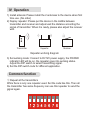
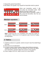
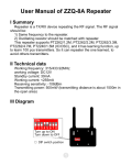
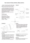
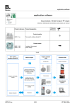
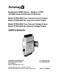
ZZQ8 New Repeater User Manual
I Summary
This is a TX/RX repeater which repeats the wireless RF signal when
the distance is not enough. Put the repeater between the transmitter
and receiver. They should meet the items as below.
1) The frequency of transmitter and repeater should be same.
2) Oscillating resistor should be matched with repeater.
3) Set repeater number while multiple repeaters are used together.
4) This repeater supports PT2240/1.5M(IC/OSC) learning code transmission protocol, it can pair up to 100pcs transmitters.
II Technical data
Working frequency: 315/433.92MHz
working voltage: DC12V
Standby current: 30mA
Working current: <255mA
Receiving sensitivity: -108dBm
Transmitting power: 500mW (transmitting distance is about 1500m in
the open area)
III Diagram
Antenna
POWE
R SEND
DC 12V
Power supply
Power LED
Send LED
Function DIP switch
Testing
Pairing
Repeat mode
Number of
repeater
Transmit time
Delete
POWER: power indiction
SEND: Repeating indication, it will be on while transmitting signal.
DIP switch:
1-3: define the number of repeater from 0~6. While only need 1
repeater in the area, put the number as 0. If need 2 or more repeater
in the area, should define the number of repeater, like 1, 2, 3, 4, 5, 6.
When use over 1 repeater, the response time will be longer.
0
1
2
3
4
5
6
4: delete the paired transmitter. (available when the repeater works in
on status of gang 6)
5: transmit time adjust. Off 6 sec; On 12 sec. (If the repeater is 0, the
transmit time is immediately)
6: when it is off, all the transmitter can be repeated; if it is on, it only
repeats the one which is paired.
7: Push to ON position to pair the transmitter. After pairing, push back
OFF position. (the gang 6 should be on.)
8: for testing.
IV Operation
1) Install antenna: Please install the 2 antennas to the device when first
time use. (No order)
2) Deploy repeater: Please put the device in the middle between
transmitter and receiver and adjust well the distance according the
signal of transmitter. When it is ready, please also adjust the receiver
well.
Repeater
Transmitter
Receiver
Repeater working diagram
3) Set working mode: Connect to DV12V power supply, the POWER
indicator LED will be on, the repeater goes into working status.
Adjust the DIP switch to select transmitting signal.
4) Set the DIP switch code for different application.
Common function
① Repeat all the transmitters
While there is only one repeater used. Set the code like this. Then all
the transmitter has same frequency can use this repeater to send the
gignal again.
② Repeat the paired transmitters
In this status, the repeater only repeat the transmitter which is paired.
When pair transmitter, switch 7 ON.
And press the transmitter button. After
pairing is finished, switch it off.
When delete paired transmitter, switch 4
ON, press the transmitter, then the one
will be deleted.
ON
Multiple repeaters
No.1
No.2
No.3
No.4
No.5
No.5
Note: if there are only 1 to 3 repeaters used. Push the 5 gang as
OFF position. If there are 4 to 6 repeaters used. Push the 5 gang
as ON position.
V Notice
1) Install the antenna to upwards, and do not put it near the metal things
and wall.
2) This device is not waterproof.
3) If receiver cannot receive signal, please adjust distance between
repeater and transmitter, up to the repeater can receive the signal
from transmitter, and then adjust the receiver to the repeater.
4) Power supply is DC12V, output current is no less 300mA