1
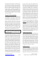
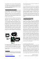
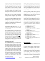
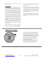
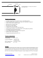
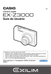
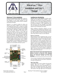
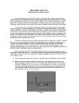
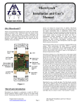
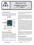
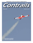
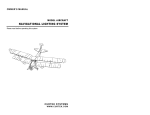
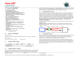
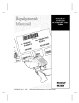
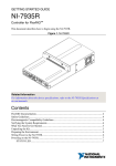
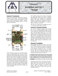
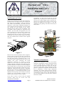
TM ThermaCowl Ultra Installation and User’s Manual OSAThermaCowl™ Ultra Thank you for purchasing the Oregon Scale Aviation Inc. ThermaCowl Ultra cowl flap control system. ThermaCowl Ultra allows the scale enthusiast to achieve the ultimate in scale realism and functionality, and enables the sport enthusiast to control engine compartment temperature as well as easily add scale like features to the sport model. This controller has been designed by R/C aviation enthusiasts with the utmost concern for reliability, safety and usability. Before installing the ThermaCowl Ultra controller, you must make the appropriate servo and receiver connections. JR, Airtronics, Hitec or Futaba servos will connect directly to the servo output pins of the ThermaCowl Ultra unit (see Figure 2 for correct polarity). Connections to the receiver for these systems can be easily made with standard aileron extenders and the supplied connectors. Retention Slots approximately 1/8” and crimp the wires into the pins supplied using a crimping tool or needle nosed pliers. Be sure the wire is firmly crimped in place, and insert all 3 leads into the supplied housing until the retention fingers snap into the housing slot (see Figure 1). Test your installation by gently pulling on the leads to insure they are firmly seated. Ground Blk/Brn +5V Red/Red Signal Yel/Or Wing Flap Input Wing Flap Output Cow l Flap Output Out 2 Connector Retention Finger FOT Adjustment Wing Flap En able Reverse Cow l Output Crimp Wire SOT Adjustment Out 2 Config EEPROM LED Figure 1. Please be sure to observe the polarities shown in Figures 2. Ground is always towards the outer edge of the board for all connectors. Note that if you do not intend to use the Wing Flap mixing feature of ThermaCowl Ultra, it is not necessary to connect a signal lead from your receiver to the controller. Only power (red/orange) and ground (black/brown) connections are necessary for correct operation. If you do connect the receiver signal lead, the controller will place a small load on that signal, but you are provided a buffered servo output to prevent overloading the receiver output. This is of concern only if you are driving multiple servos from the Wing Flap channel of the receiver. Additionally, ThermaCowl Ultra provides a configurable output that can be used as an additional buffered copy of the input signal (i.e. an extra Wing Flap output or as an additional Cowl Flap output). This would prove useful for example if you were controlling cowl flaps on a twin engine aircraft and needed 2 cowl servo outputs. Figure 2. ThermaCowl Introduction ThermaCowl was designed to enable the scale aviation enthusiast to automatically control the opening and closing of cowl or cooling flaps in a scale-like manner. As the engine compartment temperature increases, the cowl flaps open wider to allow further cooling. Because the cowl flap position is controlled by temperature, ThermaCowl Ultra aids in maintaining a constant engine compartment temperature. This provides quicker warm-ups, and fewer lean run flame-outs. This control feature was used on many of the WWII era aircraft, and you will find ThermaCowl Ultra an excellent addition to your scale project to add that final touch of realism. If you need to connect a receiver using the supplied connectors, simply strip the receiver wires back Oregon Scale Aviation Inc. www.OregonScaleAviation.com Page 1 ThermaCowlUltra Installation and User’s Manual Doc # 1003205 ThermaCowl Ultra adds the ability to optionally open the cowl flaps whenever the wing flaps (or any other channel you choose) are deployed. The further you deploy the wing flaps, the further the cowl flaps are opened. This feature allows you to verify correct operation while in the pits, and allows you to demonstrate operational cowl flaps any time the radio system is operational. The minimum and maximum cowl flap positions are fully adjustable, the point at which wing flap mixing starts is fully adjustable, and the full open position for wing flap mixing is fully adjustable. These adjustments need to be made only once, and are then stored in the controller memory, even after you remove power from the controller. ThermaCowl Ultra Installation Before installing ThermaCowl in your aircraft, it is recommended that you connect it to a receiver (or battery) on the bench-top to verify proper connections and to become familiar with the adjustments. To begin, you will verify operation as a thermal controller only. Later, if you choose, you will configure Wing Flap mixing and control. Begin by insuring all 4 switches are in the “Off” position (See Fig 2). The switch is “Off” when it is closest to the outer edge of the controller. Now insure the Start to Open Temperature (SOT) adjustment is turned fully clockwise and the Full Open Temperature (FOT) adjustment is turned fully counter clockwise. Connect the cowl servo to the “Cowl Flap Output” connector on the controller (see Fig 2). Connect the controller to any proportional output channel of the receiver. The remainder of this document will assume the use of the Wing Flap receiver output. Please insure that the power and ground leads are properly connected to ThermaCowl. Reversing power and ground may damage the ThermaCowl controller and void your warranty. Note that all ground leads on all connectors are towards the outer edge of the board. This makes it easy to quickly check for proper connection before applying power to the controller. Once connected, you can verify proper temperature control operation of the controller. Wait until the cowl flap servo stops moving (approximately 45 seconds). Slowly turn the SOT adjustment (see Figure 2) counter-clockwise (CCW) until the servo starts to move. Turn the SOT adjustment slightly CW from this position to return the servo to its original position. By setting the SOT point slightly above the point at which the servo starts to move, you have adjusted the ThermaCowl so that it will start to open the cowl flaps at slightly above room temperature. Now gently hold the temperature probe between you fingers, and the flap servo will start to slowly open (assuming your fingers are slightly warm). Note that you may not be able to achieve the full open position if you cannot heat the probe enough with you fingers to reach the full open temperature. If the servo does not move, disconnect the power source and verify all connections. If the cowl servo moves in the wrong direction for your installation as you heat the probe, simply move the Reverse Cowl Output switch (See Fig 2) to the “On” position. Once you are satisfied that ThermaCowl is functioning properly, Oregon Scale Aviation Inc. www.OregonScaleAviation.com Page 2 you may choose to make initial temperature setting adjustments on the bench using a pistol type hair dryer. To do this, simply turn the SOT adjustment fully CW and wait for the servo to stop moving. Heat the probe with the dryer to the approximate temperature that you want the flaps to start opening at. Remember that the ThermaCowl is designed to measure the temperature of the air in the engine compartment, and is not designed to be directly mounted to the engine or muffler in any manner. Doing so will overheat the probe and damage it. Additionally, the probe was not designed to tolerate the vibration associated with direct mounting to the engine or muffler. Once you have reached the temperature that you want the flaps to start opening at, and have held it for about 15 seconds, slowly turn the SOT adjustment CCW until the cowl flap servo just starts to open. You have now set the temperature at which the cowl flaps begin opening. Turning the SOT adjustment CW increases the temperature at which the cowl flaps start to open. Turning the SOT adjustment CCW decreases the temperature at which the flaps start to open. Now, increase the probe temperature to the point where you desire the cowl flaps to be fully open. Be careful not to overheat the probe. Remember this is the engine compartment temperature, and should not be so high as to blister paint or char balsa! Once you have held this temperature for about 15 seconds, turn the FOT adjustment CW until the servo starts to close. Turning FOT CCW lowers the temperature at which the flaps are fully open, turning CW increases the temperature at which the flaps are fully open. In most well ventilated cowl installations, leaving the FOT adjustment in the full CCW position will provide satisfactory results. Congratulations, you have successfully adjusted the temperature settings for the ThermaCowl Ultra controller and are now ready to proceed with installation and mixing adjustments. Installing the Temperature Probe To install the temperature probe, drill a small hole in the firewall large enough to slip a piece of silicone fuel tubing through. The hole should be placed such that when the probe is pushed through the tubing and firewall, it will rest in the air stream that flows past the top of the engine cylinder. Insert the probe through the fuel tubing and adjust it to the desired position. Generally about ¼” behind the top of the cylinder head in the cylinder head cooling fin airflow produces best results. Seal the fuel tubing and probe using a small amount of silicone sealer. If the probe has to extend from the firewall more than ½”, use a stiff tube to extend the reach. Using fuel tubing to reach more that ½” will allow the probe to vibrate excessively and may damage the probe. Make sure the probe does not contact any vibrating or moving surfaces or linkage. Installing the Cowl Servo Install the cowl servo as shown in the application examples given below. It is generally best to mount the servo and linkages inside the fuselage to avoid interference with the engine and to avoid exhaust residue on the servo. Once the servo and linkage is installed, plug the servo into the “Cowl Flap Output” connector on the controller (See Fig 2). Apply power to the ThermaCowl controller. Heat and cool ThermaCowlUltra Installation and User’s Manual Doc # 1003205 the temperature probe, and note the fully open and fully closed positions of the cowl flaps. If you are satisfied with the cowl flap fully open and fully closed endpoints, and do not intend to use the Wing Flap mixing feature, you have successfully completed the installation and can proceed to the final adjustments section. Plug in the ThermaCowl Ultra Controller If you intend to use the Wing Flap mixing feature, install the Wing Flap servo in your model and make all of the normal transmitter and linkage adjustments to insure smooth full range travel of the flaps. Pay particular attention to setting the correct servo travel direction on your transmitter. Once you are satisfied with your wing flap operation, un-plug the flap servo from your receiver and plug it into the “Wing Flap Output” connector on the ThermaCowl Ultra controller. In order to make cowl flap endpoint or wing flap mixing adjustments, connect the receiver Flap output to the Wing Flap Input of the ThermaCowl Ultra controller. This adjustment assumes a fully proportional channel is connected to the Wing Flap Input of ThermaCowl. If you use a transmitter switch for flaps, please select a proportional channel (ie Throttle) for making the following adjustments. If you use an alternate channel, you may need to temporarily reverse its output from the transmitter so that the wing flap servo moves in the correct direction. You must connect a proportional channel in order to make endpoint adjustments even if you do not plan to use the Wing Flap Mixing feature. While any proportional channel can be used to “mix” with the cowl flaps, for purposes of clarity, only wing flap mixing will be described in this document. Turn on the controller and wait approximately Receiver Wing Flap Servo Cow l Flap Servo Temp Probe the wing flap mixing feature, also plug the wing flap servo into the controller (See Fig. 3). Insure ThermaCowl is powered down. Move the EEPROM and Out 2 Config switches (Switch 3 and 4) to the “On” positions (See Fig 2). Apply power to ThermaCowl controller and turn on the transmitter. Wait approximately 25 seconds for the system to stabilize. Move the Flap knob or lever on the transmitter to the fully deployed position (flaps down position). The LED on ThermCowl Ultra controller should blink repeatedly. If it does not, move the Wing Flap Enable switch (Switch 1) to the “On” position (in this mode, the Wing Flap Enable switch serves as an input reversing switch). Verify the LED is flashing and then move the EEPROM switch to the “Off” position. Turn ThermaCowl off and return all switches to the “Off” position. Cowl Endpoint and Mixing Settings Cowl Fully Closed Position To adjust the endpoints settings, move the EEPROM switch to the “On” position. If you plan to use Wing Flap Mixing, insure the Wing Flap Enable switch is also in the “On” position. Connect the receiver Flap output to the “Wing Flap Input” on the ThermaCowl controller. Turn on the receiver and transmitter and wait until the LED flashes. You will notice that the ThermaCowl LED will flash once and then pause then repeat the flash. Let’s call this a 1Flash sequence. A 1-Flash sequence means ThermaCowl is waiting for you to set the Fully Closed cowl flap position. Note that the transmitter flap control will now let you adjust the position of the cowl flaps. Move the transmitter flap control to the “flaps up” position. The Cowl Flap servo should move to the closed position. If instead it moved to the open position, reverse the Cowl Flap direction of travel by moving Switch 2 (Reverse Cowl Output) to the “On” position. Now adjust the flap control on the transmitter until the cowl flaps move to their fully closed position. You may find it necessary to temporarily readjust your wing flap endpoints on your transmitter to achieve the fully closed position. If you do, please make a note of the original setting as you will need to return to that setting later. This will not overdrive your wing flap servos as they are disabled during this adjustment step. Once the cowl flaps are in the fully closed position, move the EEPROM switch to the “Off” position. This will store the closed cowl flap position in the non-volatile memory. Figure 3 25 seconds for the system to stabilize (DSM systems can take a significant amount of time to “Link-Up” if the Tx is very close to the Rx or there is metal near the Tx or Rx). Verify that the SOT and FOT adjustments are set such that the cowl flaps do not start to open at room temperature. Readjust if necessary. Turn the controller off by switching off the receiver. Input Reversing At this point, you should have the cowl flap servo and the receiver Flap (or any proportional channel) output plugged in to the ThermaCowl Ultra controller. If you intend to use Oregon Scale Aviation Inc. www.OregonScaleAviation.com Page 3 Cowl Fully Open at Hot Temperature Return the EEPROM switch to the “On” position and notice a 2-Flash sequence occurs (2 flashes followed by a longer pause). The 2-Flash sequence means ThermaCowl is waiting for you to program the Fully Open at Hot Temperature position. Move the transmitter flap control until the cowl flaps are in the position you desire when your engine compartment is hot and you want the cowl flaps fully open. Again, you may have to temporarily readjust the Wing Flap endpoints on your transmitter to achieve fully open cowl flaps. If you do, please make a note of the original setting as you will need to return to that ThermaCowlUltra Installation and User’s Manual Doc # 1003205 setting later. Once you have achieved the desired fully open position of the cowl flaps, move the EEPROM switch to the “Off” position. If the LED goes out, you have successfully programmed the fully open and closed position endpoints. If the LED produces a 10-Flash sequence, it means the controller sensed an Open position that was less than the Closed position. This can occur if the Input Reversing step was not correctly completed. In this case, turn the controller off and go back to the Input Reversing step, and also insure you have the Cowl Output Reversing switch in the correct position. If the LED goes out and you are not using the Wing Flap Mixing feature, you have successfully completed the ThermaCowl endpoint programming. Turn ThermaCowl off and go to the Out 2 Configuration step. Cowl Open Position When Wing Flaps Fully Deployed If you are using the Wing Flap Mixing Feature, move the EEPROM switch to the “On” position. You will notice a 3Flash sequence, indicating the controller is ready for the Cowl Flap Open Position when Wing Flaps are Fully Deployed position. Move the transmitter control until the cowl flaps are in the desired fully open position. Move the EEPROM switch to the “Off” position. Wing Flaps Fully Deployed Position If you had to adjust your transmitter wing flap endpoints/travel in the earlier steps, return the transmitter to its original settings. Move the EEPROM switch to the “On” position and notice that the controller is emitting a 4-Flash sequence. The 4Flash sequence means the controller is ready to accept the Wing Flaps Fully deployed position. Move the transmitter flap control to the fully deployed (down) position. Notice that your wing flap servo is now following the movement of the transmitter control. Insure that the wing flap is not being over driven and that it is achieving both full deployment and full closure without stalling the servo. You may need to make a fine adjustment of the transmitter endpoints/travel at this time. Once you are satisfied with the wing flaps are in the fully deployed position, move the EEPROM switch to the “Off” position. Wing Flap Mix Start Position Move the EEPROM switch to the “On” position and notice that the controller is emitting a 5-Flash sequence. The 5Flash sequence means the controller is ready to accept the Mix Start Point. You may be asking what is the mix start point? The idea behind this setting is that you may not want the cowl flaps to start opening until the wing flaps are at least 50% deployed. Maybe you prefer 80% deployed. This is very typical of full scale WWII aircraft. The cowl flap would open when the engine was hot OR would start opening when the wing flaps reached about 70% deployed. They would fully deploy when the wing flaps were fully deployed. ThermaCowl has to perform a number of mathematical computations to achieve this mixing, and it has to know at what point you want it to start opening the cowl flaps. It is recommend that you choose something around 80% wing flap deployment for this point, but Oregon Scale Aviation Inc. www.OregonScaleAviation.com Page 4 remember, cowl flaps produce drag, so don’t set the point to low. Note that this position must be less than the Wing Flaps Fully Deployed position set in the prior step. Once you have the transmitter flap control in the position you want, move the EEPROM switch to the “Off” position. If the LED goes out, you have successfully completed all of the one-time programming steps. Please go to the Out 2 Configuration step. If the LED is emitting a 10-Flash sequence, it means the Start Mixing point was greater than the Wing Flap Fully Deployed point. You must start the programming sequence over by turning off the controller and moving the EEPROM switch to the “On” position. Then repeat the Cowl Endpoint and Mixing Setting sequence. This programming sequence must be completed exactly in the order specified above. If you make a mistake in the sequence, simply move the EEPROM switch to the “On” position and power down the ThermaCowl Ultra controller. Wait a few seconds, and power back up. You can now restart the sequence from the beginning (1-Flash sequence). If you decide later to re-adjust the settings, remember that you must to go through the five settings in the following order: 1) EEPROM switch “On” (1-Flash) 2) Cowl Flap full closed endpoint 3) EEPROM Switch “Off” 4) EEPROM Switch “On” (2-Flash) 5) Cowl Flap full open position at maximum temperature 6) EEPROM switch “Off” 7) EEPROM switch “On” (3-Flash) 8) Cowl Flap full open position when wing flaps in full down position 9) EEPROM switch “Off” 10) EEPROM switch “On” (4-Flash) 11) Wing Flap transmitter knob full down/deployed 12) EEPROM switch “Off” 13) EEPROM switch “On” (5-Flash) 14) Wing Flap position when mixing starts to open cowl flaps 15) EEPROM switch “Off” Out 2 Configuration You have now completed the ThermaCowl Ultra installation programming and adjustments! You may be wondering what the Out 2 Config switch is for, and why is nothing connected to the Out 2 connector? ThermaCowl can be programmed to either provide a second Wing Flap Servo output on the Out 2 connector or provide a second Cowl Flap Output on the Out 2 connector. If for example, you have a twin engine aircraft, you may want two Cowl Servo outputs. On the other hand, if you are building a Corsair, you have 6 wing flaps to control so you might like a second wing flap servo connection (one connection for each side of the wing). ThermaCowl has you covered! If the Out 2 Config switch is “Off”, the Out 2 connector is a Cowl Flap output. If the ThermaCowlUltra Installation and User’s Manual Doc # 1003205 Out 2 Config switch is “On”, the Out 2 connector is a Wing Flap Servo output! firewall. Route all connections away from the receiver antenna and secure them appropriately. Perform a radio ground range check. Final Adjustments For final adjustments, it is recommended that you leave the ThermaCowl SOT and FOT adjustments accessible. It is also recommended that you perform final adjustments on a relatively hot day. Fully restrain your aircraft so that you can run at full throttle without holding the aircraft. This will allow you to make final adjustments safely. Turn the FOT pot fully counter-clockwise and the SOT pot fully clockwise. Power up the transmitter and receiver and start your aircraft. Once it warms up to the point that you want the cowl flaps to start opening, turn the SOT pot counterclockwise until the cowl flaps just start opening. Now warm the engine up completely and run the aircraft at full throttle for about 45 seconds. Now return the throttle to idle and allow the aircraft to idle for about a minute. You are attempting to heat the engine compartment to its highest temperature. Once you have achieved the highest temperature in the engine compartment, adjust FOT so that the cowl flaps are fully open. There is a small amount of interaction between the FOT and SOT settings, so you may need to make a final fine adjustment to the SOT after changing the FOT. Go fly and enjoy the scale realism and functionality only ThermaCowl Ultra provides. Go ahead, show it off a little to your friends in the pits by lowering the wing flaps and watching the cowl flaps open. Looking for the perfect “dirty flyby” picture? Lower the wing flaps and tell your friend to have their cameras ready when you comes by for an awesome dirty flyby! We at Oregon Scale Aviation strive to bring you the best in scale modeling accessories and hope you will have many years of enjoyment with your ThermaCowl Ultra cowl flap controller. Wrap the ThermaCowl Ultra controller in vibration damping foam (the same kind you use for mounting your receiver) and secure it to the fuselage or backside of the Application Examples Example of a single servo controlling multiple flaps. Servo rear protrudes through firewall and is sealed with silicone sealer. Slip-joints activate the flaps that do not contact a pushrod. Pushrods are not connected to flap, but simply push against flap inner surface. This allows easy removal of cowl. Attach a wearing surface on the inside of the flap and where the pushrod exits the fuselage (Jerry Nelson sells an excellent nylon bushing for this). Span a rubber band or spring across the individual flaps to ensure the flaps return to a fully closed position when the engine compartment is cold. Futaba S148 Oregon Scale Aviation Inc. www.OregonScaleAviation.com Page 5 ThermaCowlUltra Installation and User’s Manual Doc # 1003205 Cowl Flap Fuselage Cowl Cowl flaps attached to cowl using Sig Easy Hinges or Robart Hinge-Points ThermaCowl Ultra Features Automatic proportional scale control of cowl or cooling flap position Wing Flap mixing allows opening of cowl flaps when wing flaps are deployed Dual cowl flap or dual wing flap outputs Buffered copy of wing flap input Reversible cowl flap outputs Fully microprocessor controlled Adjustable start opening and full open temperatures Fully adjustable endpoints (for both temperature and wing flap mix positions) All settings stored on permanent memory. No pre-flight adjustments or stick movements required Reliable surface mount technology Designed and manufactured in the U.S.A. ThermaCowl Specifications Voltage Range Current Consumption INPUT Signal Swing Operating Temp. 4.5V – 8.5V < 10mA @ 5.0V < 15mA @ 7.0V 2.0V min, 5.3V Max 0C - 70C Warranty OSA warrants the ThermaCowl™ Ultra controller to be free from defects in materials and workmanship for a period of 90 days from the date of purchase. If your unit is defective, return to OSA and we will repair or replace the unit as deemed appropriate by OSA. This warranty does not include damage due to accidents, misuse, improper installation, tampering, radio interference, unauthorized repair or acts of God. OSA will not be responsible or pay for loss of time, loss of use, inconvenience, incidental, consequential or property damages due to the use of this product. Oregon Scale Aviation Inc. www.OregonScaleAviation.com Page 6 ThermaCowlUltra Installation and User’s Manual Doc # 1003205