1
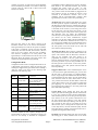
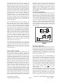
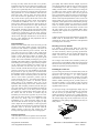
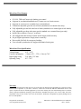
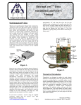
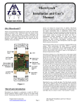
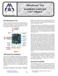
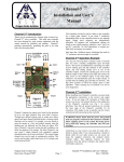
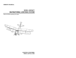
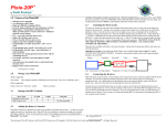
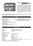
MicroGearTM Ultra Installation and User’s Manual MicroGear™ Ultra Installation Landing Gear Introduction Thank you for purchasing the Oregon Scale Aviation Inc. MicroGear Ultra servo control system. This controller has been designed for scale aviation enthusiasts by scale aviation enthusiasts with the utmost concern for reliability, functionality and usability. MicroGear Ultra is a fully adjustable and highly capable landing gear and landing gear door controller. It uses a single input from the receiver to control the sequencing of up to four servos to create realistic landing gear and door movements. You can even configure MicroGear to cause the main gear retractions to occur staggered from each other just like the full scale counterpart. With standard servos, the landing gear, tail wheel and door speeds can be adjusted to move at realistically slow speeds. MicroGear is an advanced controller for adding scale realism to your aircraft. It supports P51, P61 and Corsair style landing gear and gear doors. It supports air actuated or servo actuated retracts and gear doors and is compatible with electric retracts (electric retracts must use the original OEM controller). Additionally, it supports either standard or retract style servos. MicroGear Ultra allows you to control the movement of up to 4 servos (Main and Staggered Gear, Doors and Tail Wheel) when you actuate the landing gear switch on your transmitter. For standard servo based installations, the gear door and landing gear movement rates can be individually adjusted. Gear door closing can begin after a user adjustable delay, or after an optional “Gear-Up” switch closes. All servo movements are reversible through reversing switches. All servo endpoints are fully adjustable and permanently stored in memory. After completing a one-time installation and adjustment, no pre-flight stick movements or adjustments are required. Simply turn on your transmitter and receiver and fly! Ground Blk/Brn +5V Red/Red Signal Yel/Or Nose Door/ P51 & Cors Stagger Gear/ LED Receiver Input Main Gear Main Gear Doors Gear Speed/Delay Reverse Gear Reverse Doors Rev Tail/Nose Doors Configure Door Speed/Delay Gear Up Switch Input Signal Yel/Or +5V Red/Red Ground Blk/Brn Tail Wheel or P61/TSR Stagger Gear Figure 1 Oregon Scale Aviation Inc. www.oregonscaleaviation.com Page 1 Before installing the MicroGear controller, you must complete some initial configuration and adjustments. There are 3 configuration modes. Each mode is entered by setting the switches to unique positions, and then powering on the unit. These instructions will walk you through each of the modes. Please perform all steps in the order indicated. Receiver Connection Before entering any of the configuration modes, you must connect the receiver “Gear” output to the MicroGear input. The MicroGear Receiver Input is in the upper left corner of the board as shown in Figure 1. You will need a male to male connecting wire of the appropriate length for your type of radio system. If you cannot purchase a male to male connector, you can use the included connector and a servo pigtail or aileron extender to complete this connection. Please refer to the “Installing the Connector” section at the end of this document for instructions. Before powering-up the MicroGear Ultra, insure that the power, ground and signal wires are in the correct locations as specified in Figure 1. Note that ground is always on the outside edge of the controller for all 6 connectors. Please insure that the power and ground leads are properly connected to MicroGear before applying power to the system. Reversing power and ground will damage the MicroGear controller and void your warranty. If you are using a transmitter that allows programming the servo travel speeds, insure the Gear channel is programmed for normal or full speed travel. Input Setup Mode: The Input Setup Mode is used to configure the input signal direction. Make sure the receiver is connected to MicroGear and that the receiver and MicroGear are off. Move Switch 4 (Configure) and Switch 3 (Rev Tail/Nose Doors) to the “On” position. Plug the LED module into the LED connector in the upper right corner of the MicroGear MicroGear Ultra Installation and User’s Manual Doc # 105109 controller (see Figure 2). Insure that the travel adjustment for the transmitter gear channel is set to deliver a full range of travel (-100% to +100% for JR or 100% travel in both directions for Futaba). Figure 2 Move the Gear switch to the “Down” position on the transmitter and then turn on the receiver and transmitter. Wait approximately 20 seconds for the system to stabilize. If the input is configured correctly, the LED will blink continuously. If it does not blink, move Switch 1 (Reverse Gear) to the “On” position. Once the LED is blinking, move Switch 4 (Configure) to the “Off” position, wait approximately 5 seconds and then turn off the receiver and MicroGear. Move all switches to the “Off” position. This completes the Input Setup Mode programming. Configuration Mode Configuration mode is used to configure MicroGear for Air or Mechanical gear and doors, setting the gear door style, enabling the staggered main gear feature and for enabling a “Gear-Up” switch. This mode sets the following eight parameters in the following order; LED Flashes 1 2 Function Air Actuated or Electric Gear 4 Air Actuated Doors Staggered Main Gear Corsair Mode 5 P51 Mode 6 7 P61 Mode TSR Mode 8 “Gear-Up” Switch Enable 3 Comments Use Air configuration for air or electric retracts or retract style servos Use Air configuration for air or retract style servos Doors remain open after gear are down Doors close after gear are down Enables nose doors Main doors close after gear are down, nose door open when gear down Normally open switch between ground and signal pins of Switch input Air/Mech Gear: Notice that the LED flashes once, pauses and then repeats the sequence continuously. This indicates that MicroGear is ready for the Air Actuated Gear setting to be programmed. If your aircraft uses air actuated main gear or tail wheel, electric retracts or you are using retract servos for the main gear or the tail wheel, move Switch 1 to the “On” position. If you are using electric retracts, please note that Microgear does not replace the manufacturers controller. If you are using MicroGear with electric retracts, you MUST use the retract manufacturers original controller. You will later simply plug the manufacturer’s controller into MicroGear, instead of into the receiver. If you are using only standard servos with mechanical retracts and a standard servo on the tail wheel, move Switch 1 to the “Off” position. Now move Switch 4 to the “Off” and notice that the LED stops flashing. Air/Mech Gear Doors: Move Switch 4 (Configure) to the “On” position and notice that the LED flashes 2 times and repeats. This indicates that the MicroGear controller is ready for the Air/Mech Gear Door setting to be programmed. Set Switch 1 to the “On” position if you are using air actuated gear doors or are using retract servos on any of the gear doors. If you are using a standard servo on all of the gear doors, move Switch 1 to the “Off” position. Move Switch 4 to the “Off” position and notice that the LED stops flashing. Staggered Main Gears: If have installed separate servos or air valves for the right and left main gear, you can cause the main gear to raise and lower in a staggered fashion. This is very prototypical of WWII aircraft. One side always pressurized before the other and so one gear would always raise and lower before the other. Move Switch 4 to the “On” position and notice that the LED flashes 3 times and repeats. Move Switch 1 to the “On” position to enable main gear staggering or to the “Off” position to disable main gear staggering. Move Switch 4 to the “Off” position and notice that LED stops flashing. Corsair Mode: Corsair landing gear doors open and remain open while the landing gear are down. Move Switch 4 to the “On” position and notice that the LED flashes 4 times and then repeats. If you are using Corsair style doors, move Switch 1 to the “On” position; otherwise leave it in the “Off” position. Move Switch 4 to the “Off” position and notice that the LED stops flashing. Note that you can only program one door style. If you attempt to set more than one door style (ie setting both P51 Style Doors and Corsair Style Doors), the LED will flash rapidly 10 times and repeat until the controller is turned off. In that case reprogram all Configuration Mode settings. You must complete the entire sequence (through Gear Up Switch Enable) in order for any configuration settings to be saved. Do not interrupt or terminate the configuration Oregon Scale Aviation Inc. www.oregonscaleaviation.com programming without completing the sequence through 8 LED blinks or the MicroGear firmware may become corrupted and require repair by OSA. To enter Configuration Mode, move both Switches 2 and 4 to the “On” position. Insure the LED module is plugged into the LED connector (see Fig. 2) and that the receiver is still connected to the MicroGear controller. Turn on the transmitter and the receiver/MicroGear controller. Wait approximately 20 seconds to insure the system links up. Page 2 P51 Mode: P51 Mustang landing gear doors open to allow the landing gear to lower, and then return to the closed MicroGear Ultra Installation and User’s Manual Doc # 105109 position once the landing gear are down. Move Switch 4 to the “On” position and notice that the LED flashes 5 times. If you are using P51 style gear doors, move Switch 1 to the “On” position; otherwise leave it in the “Off” position. Move Switch 4 to the “Off” position and notice that the LED stops flashing. P61 Mode: The P61 uses a tricycle style landing gear system. The P61 Black Widow main and nose landing gear doors open to allow the landing gear to lower and remain open. Due to the larger number of servos, an extra output is provided for the nose gear door. To enable P61 mode, move Switch 4 to the “On” position and notice that the LED flashes 6 times. Again, you can only set one door style. If you are using P61 style gear doors, move Switch 1 to the “On” position; otherwise leave it in the “Off” position. Move Switch 4 to the “Off” position and notice that the LED stops flashing. TSR Mode: The TSR uses a tricycle style landing gear system. The TSR nose gear doors open to allow the landing gear to lower and remain open. The TSR main gear doors open to allow the main gear to raise or lower and then close after the main gear are either fully raised or lowered. To enable TSR mode, move Switch 4 to the “On” position and notice that the LED flashes 7 times. Again, you can only set one door mode. If you are using TSR style gear doors, move Switch 1 to the “On” position; otherwise leave it in the “Off” position. Move Switch 4 to the “Off” position and notice that the LED stops flashing. Gear-Up Switch Enable: The use of a Gear-Up switch prevents the gear doors from closing until the landing gear are fully retracted. The Gear Up switch is not necessary if you are using mechanical gears with standard servos. If you choose not to use a Gear-Up switch and use air retracts, MicroGear will wait a fixed period of time after retracting the main gear before closing the doors. This time delay time is user adjustable. The problem with user programmable delays is that if you have low air pressure or an air leak, the gear may not be fully retracted before the doors start to close. This can cause the doors to interfere with the landing gear. Instead, a switch can be placed at each retract and the switches can be wired in series. Since the switches are Normally Open, all switches must be closed before the doors will begin closing when using this mode. Move Switch 4 to the “On” position and notice that the LED flashes 8 times. Move Switch 1 to the “On” position if you intend to use a Gear-Up switch or switches, otherwise leave it in the “Off” position. Move Switch 4 to the “Off” position and notice that the LED stops flashing. This completes the Configuration Mode programming. Wait 5 seconds and then turn the receiver and MicroGear controller off and return all switches to the “Off” position. Travel Limits Mode The Travel Limits Mode is used to set the travel limits for the main gear and the tail wheel (Corsair or P51 mode) or the main gear and nose doors (P61 or TSR mode). This allows you to have individually tailored limits for the gear doors, main gear and the tail wheel/nose doors while using only a single transmitter channel to control the landing gear. The main gear door travel limits are adjusted using Oregon Scale Aviation Inc. www.oregonscaleaviation.com Page 3 the travel adjustment on the transmitter. If you are using air actuated gear or retract style servos for the doors and the gear, this adjustment is not necessary. If you use standard servos on either the main gear, the tail wheel or nose door, you should complete this adjustment. If you have several servos tied together (using Y-connectors or otherwise) to actuate doors or gear, insure that all gear or doors that are tied together move in the same direction. Insure the LED module is plugged into the MicroGear controller (see Fig. 2). Disconnect all gear doors from MicroGear and lower all gear doors manually. Connect the main gear servo to the Main Gear connector on the MicroGear controller (See Fig 1). Insure the black or brown ground wire is towards the outside edge of the board. Move Switch 4 to the “On” position, and all other switches to the off position. Move the transmitter gear/retract switch to the down position. Turn on the transmitter and the receiver. Wait approximately 6 seconds for the system to stabilize (DSM radios may require up to 20 seconds to “Link-up”). The system has stabilized when the LED flashes once, and then repeats. Now move the transmitter gear/retract switch to the up position. If the main landing gear do not move in the up direction, reverse the Main Gear servo output by moving Switch 1 (Reverse Gear) to the “On” position. Move the Transmitter gear/retract switch to the down position and verify that Main gear lower. The LED should be flashing once and repeating indicating it is now ready to accept the gear down travel limit. Adjust the transmitter travel limit for the gear/retract channel until the main landing gear (or the air valve servo for air actuated systems) are in the full down position, but the servo is not binding. If you are using Lado linear actuators, set the Tx travel limit to the default 100%. Once satisfied with the servo down position, move Switch 4 to the “Off” position. The LED will stop flashing. Move Switch 4 to the “On” position and the LED will flash twice and then repeat. This indicates that MicroGear is ready to accept the gear up travel limit. Move the transmitter gear/retract switch to the up position and then adjust the transmitter gear/retract channel travel limit until the main gear (or air valve servo) is completely up, but not binding or stalling the servo. If using electric retracts that do not support Tx programmable travel limits, set the Tx travel limit at the default 100%. Once satisfied with the up position, move Switch 4 to the “Off” position. The LED should stop flashing. If the LED flashes 10 times rapidly and repeats, it means that it received a gear up position that was lower than the gear down position. This can occur if you failed to properly configure the input in the Input Setup Mode. In this case, power the system down, and repeat the Input Setup Mode and Travel Limits Mode adjustments. With the system still powered up, disconnect the main and nose gear servos from MicroGear and move the nose and main gear to the up position. If you are using the TSR or P61 modes, plug the nose door servo into the Tail Wheel Output of MicroGear (it will be later moved to the Nose Door Output when the LED is removed). If you are using the Corsair or P51 mode, connect the tail wheel servo to the Tail Wheel Output on MicroGear. MicroGear Ultra Installation and User’s Manual Doc # 105109 Move the MicroGear Switch 4 to the “On” position. The LED will flash 3 times and then repeat, indicating the MicroGear controller is ready to accept the Tail Wheel or Nose Door down travel limit position. Even if you are not using the Tail Wheel output, you must complete this step (in this case just set the Tx travels to 100% to complete this step). Move the Tx gear switch to the down position. If the tail wheel or nose doors travel in the wrong direction, you can reverse the travel by moving Switch 3 (Reverse Tail Wheel/Nose Door) to the “On” position. With the Tx gear/retract switch in the down position, adjust the transmitter travel limit for the gear/retract channel until the tail wheel or nose door is in the full down position, but is not binding or stalling the servo. Once satisfied with the down position, move Switch 4 to the “Off” position. The LED will stop flashing. Gear-Up Switch Installation The Gear-Up switch prevents the doors from closing until the gear are fully retracted. Gear-Up switches must be a Normally Open switch, and the switch must be installed so that it closes when the gear have been retracted enough to no longer interfere with the landing gear doors. If you plan to use a single Gear-Up switch, it must be connected between the Signal and Ground pin on the Switch Input (see Fig. 1). If you plan to use multiple Gear-Up switches, connect them in series so that all switches must be closed in order to complete the circuit (see Figure 3). If you use only one switch in the system, place the switch on the slowest or last gear to retract. Normally Open Move the MicroGear Switch 4 to the “On” position. The LED will flash 4 times and then repeat, indicating the MicroGear controller is ready to accept the Tail Wheel or nose door up travel limit position. Move the transmitter gear switch to the “Up” position and adjust the transmitter travel limit for the “Gear” channel until the tail wheel or nose door is in the full up position, but is not binding or stalling the servo. Once satisfied with the up limit, move Switch 4 to the “Off” position. The LED should stop flashing. If the LED flashes 10 times rapidly and repeats, it means that it received a tail wheel/nose door up position that was lower than the tail wheel down position. This can occur if you failed to properly configure the Tail Wheel/Nose Door reversing switch. In this case, power the system down, and repeat the Travel Limits Mode adjustments paying particular attention to the Tail Wheel/Nose Door reversing switch. gear/retract switch to the down position and adjust the transmitter gear channel end point or travel adjust to insure the gear doors fully open but do not bind or stall the servo. Again, the new setting only takes affect when the transmitter switch is toggled from the up to the down position, so it may take a few iterations to achieve the final travel adjustment. This completes the gear door travel limits adjustment. Single Gear-Up Switch Normally Open Normally Open Multiple Gear-Up Switches This completes the programming of the gear, tail wheel and nose door travel limits. Turn off the receiver/MicroGear controller and remove the LED module. If using the P61 or TSR mode, move the nose door servo to the Nose Door/Stagger Gear connector on MicroGear (upper right hand connector Fig 1) Main Gear Door Travel Limits Before finalizing the installation, you should set the gear door travel limits. This is done simply by adjusting the travel limits of the landing gear/retract channel on the transmitter. Insure that the main gear and tail wheel are retracted before proceeding. Disconnect all servos from the controller and plug the gear door servo(s) into the “Main Gear Doors” connector. This is the middle connector on the left side of the board. If you are using a “Gear-up” switch, plug it into the Gear Up Switch Input. Move the transmitter landing gear/retract switch to the down position. Turn on the transmitter and receiver and wait for the system to stabilize. Move the transmitter landing gear/retract switch to the up position. If the doors travel in the wrong direction, reverse the doors by moving Switch 2 to the “On” position. Adjust the transmitter gear/retract channel end point or travel adjustment until the gear doors are fully closed but are not binding and stalling the servo. Note that the new setting only takes affect when the switch is moved from the down to the up position, so you may have to adjust the transmitter limit and toggle the Tx switch several times to achieve the final setting. Now move the transmitter Oregon Scale Aviation Inc. www.oregonscaleaviation.com Page 4 Figure 3 Speed/Delay Adjustments The Gear Speed/Delay potentiometers (pots) are used to adjust the door and gear movement speeds and delays. For mechanically actuated doors, the Door Speed/Delay pot sets the speed at which the doors open and close. For air actuated doors, the Door Speed/Delay pot sets the delay between the activation of the door air valve, and the activation of the gear servo/valve. For mechanically actuated gear, the Gear Speed/Delay pot adjusts the speed at which the gear raise or lower, and for air actuated gear, the Gear Speed/Delay pot adjusts the delay between the activation of the gear air valve and the activation of the door servo/valve. Turning either pot counterclockwise lowers speed or increases delay. If you are using a “Gear-Up” switch, no further sequencing will occur until the gear are up and the switch is closed. Note that for a gear-up cycle, the doors will not start closing until all Gear-Up switches are closed and the Gear Delay time has expired. For air operated systems, it is advised that you set the delay pot fully counterclockwise to begin with, and then carefully adjust downwards insuring that the doors are not allowed to interfere with the gear. The delays are very long in this position, so be patient and you will quickly become familiar with the system. It is advised to error on the side of MicroGear Ultra Installation and User’s Manual Doc # 105109 too long of a delay rather that too short as air pressure, temperature and wear may slow down the movement of air systems over time. It is also safest and recommended that you use servos (preferably mini-servos) on the gear doors and use gear-up switches as it removes most if not all of the delay guesswork. In a Corsair installation with mini-servo driven doors and a gear-up switch, the retracts will not lower until the doors are guaranteed to be open (the pot only controls the door speed), and the doors will not start closing until the Gear-up switch is closed. This guarantees a no-interference installation. For a P51 or P61 with air driven retracts, mini-servo doors and a gear-up switch, the gear will not lower until the doors are open, but the doors will close after the user adjusted door delay – only one delay to adjust. This delay is for the gear going down which is generally a very predictable time. For the P51 up-cycle, no delays are required due to the use of the “Gear-up” switch. Using high torque standard servos with mechanical retracts for the main gear and mini-servos on the doors in the P51 or P61 eliminates all delay adjustments and the associated risk of interference. Final Installation Remove the LED module and connect the main gear and gear door servos being careful to observe correct polarity. Connect the limit switch(es) if applicable, and insure the switch(es) activate when the gear are retracted. Move all gear, doors and servos by hand to their normal down positions (the position they would be in if the landing gear switch is down). MicroGear assumes the landing gear switch is in the down position when you power up the system. This avoids accidentally retracting the gear on your beautiful scale airplane while it is still sitting on the ground and breaking off or crushing your gear doors! If you power up the system with the landing gear switch in the up position, MicroGear will drive the gear doors open for about 5 seconds, and will then drive the gear to their down position. If you have a P51 style installation, the fact that the gear doors are open on power-up is an indication that the transmitter switch is in the up position. Once you move the transmitter switch to the down position, the doors will return to their normal “gear-down” position (open for Corsair, closed for P51 etc.). It is always good practice to insure the landing gear switch is in the down position before turning on the transmitter and to turn on the transmitter before turning on the receiver. Fill the air tank if applicable. With everything connected, and the delay pots set to safe positions, turn on the transmitter and insure the transmitter gear switch is in the down position. Suspend your airplane on a stand or hold it off the ground. Turn on the receiver and wait for about 10 seconds. Flip the transmitter gear switch to the up position. If you are in P51 mode, the gear doors will start to open immediately. They may move very slowly, and if so adjust the Door Speed/Delay pot to a more appropriate setting. The gear will retract after the doors are open, and again, you may want to adjust the Gear Speed/Delay to a more appropriate value. Wait until all sequences have stopped. Now flip the transmitter switch to the down position and watch the realistic sequence of the gear door opening, the gear lowering and if appropriate, the gear door closing again! gear rapidly. This would be used for example, if you loose power during climb-out while the gear are raising, and need to immediately lower them to complete an emergency landing. Fail-safe mode is entered any time you change the Tx landing gear switch position while either the gear or gear door servos are moving. In this event, the gear will move at high speed to either the raised or lowered position depending on your transmitter switch position. The stagger feature will be temporarily disabled in order to achieve the fastest possible safe cycle. Once a fail-safe cycle has been completed, normal operation will resume without powering down the controller. Because air restrictors are typically used in air actuated systems, and because electric retracts moved at a fixed rate, the fail-safe feature is forced to wait the entire length of the user programmed delays before completing each sequence if air gear, air doors or electric retracts are used. Complete the final fine tuning and familiarize yourself with failsafe mode as described above. Once installation is completed the system is both maintenance and adjustment free. Simply turn it on and fly! Resetting to Factory Defaults It is possible to program travel limits that will leave MicroGear essentially non-functional. If this occurs, you can restore the factory values by powering up MicroGear with all four switches in the “On” position. Wait about one minute, and then power down MicroGear. Return all switches to the off position. We at Oregon Scale Aviation have worked to provide you with the best in scale modeling realism. We truly hope that MicroGear Ultra will provide you with years of enjoyment, trouble free operation and scale performance. Installing the Connector: If you are using a JR, Airtronics or Futaba radio system, the servos will connect directly to the servo output pins of the MicroGear unit (see Figure 1 for correct polarity). Connections to the receiver for these systems can be made with female to female connectors. If you cannot purchase a female to female connecting wire for you radio system, use and aileron extender or servo pigtail. If using an aileron extender, cut the male connector off and replace it with the supplied female connector. To attach your wiring to the supplied pins, simply strip the servo or receiver wire back approximately 1/8” and crimp the wire into the pin provided using a crimping tool or needle nosed pliers. Be sure the wire is firmly crimped in place, and insert all 3 leads into the supplied housing until the retention fingers snap into the retention slots. Test your installation by gently pulling on the leads to insure they are firmly seated. Retention Slots Retention Finger Crimp Wire Fail Safe Operation A fail-safe feature has been incorporated in the MicroGear Ultra unit, in the event that you need to lower or raise the Oregon Scale Aviation Inc. www.oregonscaleaviation.com Page 5 Figure 4 MicroGear Ultra Installation and User’s Manual Doc # 105109 MicroGear Ultra Features P51, P61, TSR and Corsair style landing gear control Supports air, mechanical(standard servo), retract servo or electric retracts Supports air, retract servo or standard servo actuated doors Transmitter adjustable gear door travel limits (standard servo actuated doors only) Fully adjustable gear and tail wheel travel limits (standard servo actuated gear & tail wheels) Fully adjustable gear door and retract speeds (standard servo actuated doors/gear only) Install with or without “Gear-up” switch(es) All configuration data and travel limits stored in non-volatile memory No pre-flight requirements. Simply turn it on and fly! Recoverable Fail Safe for emergency landings User selectable synchronized or staggered mechanical main gears MicroGear Ultra Specifications Voltage Range Current Consumption Input Signal Swing Operating Temp. 4.5V - 8.5V < 10ma (4.5V – 5.5V) <15ma @ 7.0V 2.0V Min, 5.3V Max 0C - 70C Warranty OSA warrants the MicroGear Ultra unit to be free from defects in materials and workmanship for a period of 90 days from the date of purchase. If your unit is defective, contact OSA for Return Material Authorization and we will repair or replace the unit as deemed appropriate by OSA. This warranty does not include damage due to accidents, misuse, improper installation, tampering, radio interference, unauthorized repair or acts of God. OSA will not be responsible or pay for loss of time, loss of use, inconvenience, incidental, consequential or property damages due to the use of this product. Oregon Scale Aviation Inc. www.oregonscaleaviation.com Page 6 MicroGear Ultra Installation and User’s Manual Doc # 105109