1
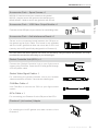
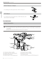
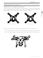
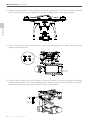
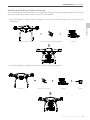
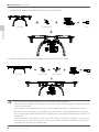
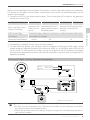
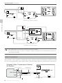
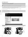
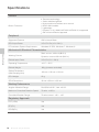
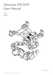
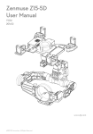
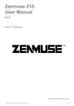
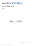
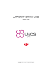
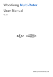
ZENMUSE H4-3D
User Manual
V1.0
2015.1
Warning & Disclaimer
The Zenmuse H4-3D gimbal is calibrated before delivery. No adjustment or modification to the
gimbal is required or recommended.
Ensure the camera is mounted to the gimbal before powering on your aircraft.
The H4-3D gimbal is finely calibrated according to the specified camera model and lens (GoPro
Hero4 Black) before delivery. You do not need to perform extra calibration. Do not attempt to
modify the gimbal or mount extra components/devices (such as a filter, lens hood, etc.) to the
camera. Be sure to use a DJI approved battery, otherwise the performance of the gimbal may be
affected.
The H4-3D gimbal is compatible with following DJI flight control systems: NAZA-M, NAZA-M V2,
WooKong-M, Phantom 2 and A2. To optimize the gimbal’s performance, download the relevant
Assistant for your flight controller and upgrade the firmware.
Make sure to operate your aerial system in the safest manner possible. We strongly recommend
that you remove all propellers, use a power supply from the R/C system or flight pack battery,
and keep children away when calibrating and configuring the gimbal. Observe the procedures
contained in this manual to mount and connect gimbal to your aircraft. Users of this product
should respect the AMA’s National Model Aircraft Safety Code.
DJI has no control over use, setup, final assembly, modification (including use of non-specified
DJI parts i.e. motors, ESCs, propellers, etc.) or misuse, and no liability shall be assumed
nor accepted for any resulting damage or injury. By the act of use, setup or assembly, the
user accepts all resulting liability. DJI assumes no liability for damage(s), injuries or legal
responsibilities incurred directly or indirectly from the use of this product.
DJI and Zenmuse are registered trademarks of DJI. Names of product, brand, etc., appearing in
this manual are trademarks or registered trademarks of their respective owner companies. This
product and manual are copyrighted by DJI with all rights reserved. No part of this product or
manual shall be reproduced in any form without the prior written consent or authorization of DJI.
Legend
Important
2 © 2015 DJI. All Rights Reserved.
Hints and Tips
Contents
Warning & Disclaimer
2
Legend
2
Profile
4
In The Box
4
Installation
6
Gimbal Description
6
Installing H4-3D onto an Aircraft
7
Camera Installation
11
Final Checks
11
GCU Connection 12
Connecting the GCU and Flight Control System
12
GCU and Flight Control System Connection
13
Video Connection
14
Configuration
16
Driver and PC Assistant Installation
16
PC Assistant Interface
16
Channel Setting
16
Firmware & Software Upgrade
17
Test Flight
18
Pre-flight Checklist
18
Gimbal Test
18
Appendix
19
Troubleshooting
19
Settings When Using the A2 Flight Control System
19
Specifications
20
© 2015 DJI. All Rights Reserved.
3
Profile
The Zenmuse H4-3D gimbal offers excellent stabilization features for aerial hobbyists and
professional aerial photographers. Powered by a built-in IMU (Inertial Measurement Unit) and
a special servo module, this gimbal is built to hold a GoPro camera and enables stable, quality
aerial photography.
Profile
The H4-3D gimbal is designed for GoPro Hero4 Black camera. Using other type of camera
may cause the gimbal to function abnormally.
In The Box
Gimbal × 1
Built-in servos and a stand-alone IMU provide yaw, roll, and
tilt stabilization. Pre-installed vibration absorbers greatly
reduce vibrations.
Damping Unit × 1
The upper plate of the damping unit is used to connect the
gimbal to your aircraft. An integrated bottom damping plate
minimizes installation time.
Accessories Pack – Spare Vibration Absorbers × 4
Spare vibration absorbers for the damping unit. Use one set
at a time.
Accessories Pack – Anti-drop Kit × 4
Spare anti-drop kits that are used to secure the upper and
bottom plates of the damping unit.
Accessories Pack – Camera Securing Bracket × 1
Camera mounting bracket.
4 © 2015 DJI. All Rights Reserved.
ZENMUSE H4-3D User Manual
Accessories Pack – Spare Screws × 1
M2.5x6.3: Used to mount your camera to the gimbal.
M2.5x5: Used to secure the gimbal to the damping unit.
M3x8, M3x6.5: Used to secure the gimbal to the aircraft.
In The Box
Accessories Pack – USB Video Output Module × 1
Connects to the USB port of your camera, for transmitting video.
Accessories Pack – Anti-interference Board × 1
Serves as the connecting board between the G8 port on
the gimbal and an 8-pin cable. This board is only available
with the H4-3D gimbal that does not come with a GCU unit
(namely, the H4-3D specifically designed for a Phantom 2).
You can mount the H4-3D gimbal onto other DJI aircraft by using the below accessories. You may
purchase the accessories according to your aircraft type.
Gimbal Controller Unit (GCU) × 1
Connect the Gimbal Controller Unit to your flight control
system using CAN-Bus. Power the GCU and gimbal through
a 3S~6S power cable.
Gimbal Video Signal Cable × 1
For connecting the gimbal controller unit to your wireless
video transmission module. Transmits the video signal.
CAN-Bus Cable × 1
Use CAN-Bus to connect the GCU to your flight control
system.
8-Pin Cable × 1
For connecting your Phantom 2 to the G8 port of the GCU.
Phantom 2 (old version) Adapter
For installing the H4-3D gimbal onto older versions of the
Phantom 2.
© 2015 DJI. All Rights Reserved.
5
ZENMUSE H4-3D User Manual
F450 & Phantom 1 Adapter
For installing the H4-3D gimbal onto a F450 or Phantom 1.
Installation
F550 Adapter
For installing the H4-3D gimbal onto a F550. Must be used
with the above F450 adapter.
Installation
Gimbal Description
Ensure the gimbal servos are unobstructed, otherwise they may be damaged during operation.
If the gimbal becomes obstructed during operation, power off and clear all obstructions
immediately.
Always mount the camera before powering on the gimbal.
[1]
[8]
[2]
[3]
[4]
[7]
[6]
[1] Yaw servo driver module [2] Upper plate of the damping unit
[3] Vibration absorbers [4] Bottom plate of the damping unit
6 © 2015 DJI. All Rights Reserved.
[5]
[5] Tilt servo driver module
[6] Roll servo driver module
[7] Camera mount
[8] 8-pin connector port (to GCU/Phantom 2)
ZENMUSE H4-3D User Manual
Installing H4-3D onto an Aircraft
Installing H4-3D onto a Phantom 2 (new version)
There are two versions of the Phantom 2. The latest Phantom 2 can hold the H4-3D gimbal
directly, while the older version of the Phantom 2 requires an adapter to hold the H4-3D. The
difference between the two versions can be seen on the bottom of Phantom.
Installation
Phantom 2 (new version)
Phantom 2 (oid version)
Follow the instructions below to install the H4-3D gimbal onto a Phantom 2 (new version).
1. Insert the securing pins into the holes on the upper plate of the damping unit as shown
below. Then, attach the upper plate of damping unit to the Phantom 2 with four M3x5 screws.
© 2015 DJI. All Rights Reserved.
7
ZENMUSE H4-3D User Manual
2. Attach the bottom plate of the damping unit to the upper plate. To do this, insert the securing
pins on the tip of the vibration absorbers into the mounting holes on the bottom plate.
Installation
3. Cover the securing pins with washers to lock the damping unit in place. Only push the
washers past the first nut.
4. Plug the 8-pin cable from the Phantom 2 into the Phantom 2 port on the anti-interference
enhancement board. Then use the supplied 8-pin cable to connect the H4-3D port on the antiinterference enhancement board to the 8-pin port on the gimbal.
8 © 2015 DJI. All Rights Reserved.
ZENMUSE H4-3D User Manual
Installing the H4-3D onto Other DJI Aircraft
You can install the H4-3D onto other DJI aircraft by using the corresponding adapter. Refer to the
relevant instructional video or user manual for more details.
1. Use the Phantom 2 (old version) adapter to install the H4-3D onto previous versions of the
Phantom 2.
Installation
Phantom 2 (old version)
Phantom 2 (old version) adapter
H4-3D
2. Use the Phantom 1 adapter to install the H4-3D onto the Phantom 1.
Phantom 1
Phantom 1 adapter
H4-3D
GCU
© 2015 DJI. All Rights Reserved.
9
ZENMUSE H4-3D User Manual
3. Use the F450 adapter to install the H4-3D onto the DJI F450.
DJI F450
F450 adapter
H4-3D
GCU
Installation
4. Use the F450 adapter and F550 adapter to install H4-3D to DJI F550.
DJI F550
F450 adapter
F550 adapter
H4-3D
GCU
Aircraft, camera, and accessories are not included with the gimbal.
Camera must be aligned to face the nose of the aircraft, and the gimbal should be parallel
with the aircraft itself.
The gimbal is calibrated before delivery. Do not attempt to adjust or calibrate it yourself.
Do not remove any screws in the gimbal, which may result in reduced performance or failure.
Do not unplug any cable attached to the gimbal ports or change the mechanical structure of
the gimbal.
The 8-pin port on the H4-3D should only to be used to connect the gimbal to your aircraft.
Do not connect other devices (such as a 5.8G video downlink transmitter) to this port,
otherwise the gimbal may be damaged.
10 © 2015 DJI. All Rights Reserved.
ZENMUSE H4-3D User Manual
Camera Installation
Follow the instructions below to mount your GoPro Hero4 Black camera.
Visit http://www.dji.com/product/zenmuse-h4-3d/video and watch the installation video
tutorial before mounting your GoPro camera to the H4-3D gimbal.
The gimbal cables are delicate items, handle with extreme care. Always check all connections
before each flight and ensure they are secure.
Final Checks
Ensure the installed damping unit is parallel with the aircraft.
© 2015 DJI. All Rights Reserved.
11
Installation
1. Connect the video output board to the gimbal using the connection cable. Ensure the connection
orientation is correct.
2. Mount the camera onto the gimbal and secure the camera with the camera bracket and screws.
3. Firmly insert the video output board into the mini-USB port on the camera to complete the installation.
GCU Connection
Skip this chapter if you have the Phantom 2 version of the H4-3D gimbal, as it does not
come with a GCU.
The GCU must be connected to the flight control system before it is powered on.
Be sure to mount the camera onto the gimbal before powering on the aircraft and the
gimbal. Otherwise the servos may be damaged due to an incorrect center of gravity.
Re-calibrate the remote control whenever the NAZA-M firmware is upgraded.
Ensure all connections are correct, otherwise damage to the gimbal or the flight control
system may occur.
GCU Connection
GCU Port Description
3S~6S
G8
Connect to a battery for GCU or gimbal power.
Connect to the G8 pin port on the gimbal for signal transmission.
Connect to a PC to upgrade the firmware using PC Assistant.
Connect to a flight control system.
Connect to a wireless video downlink module.
Connecting the GCU and Flight Control System
The GCU can be either vertically or horizontally installed on the Phantom 2. Follow the procedure
below to complete the connection between the GCU and the flight control system.
1. Upgrade the flight controller’s firmware and PC Assistant to the latest version, as shown in
the table below:
Flight Controller
A2
WKM
NAZA-M V2
NAZA-M
PC Assistant
V1.20 (or higher)
V2.00 (or higher)
V2.12 (or higher)
V2.12 (or higher)
Firmware Version
V2.10 (or higher)
V5.22 (or higher)
V3.12 (or higher)
V3.12 (or higher)
2. Complete the connection to the flight control system as shown on the table below. NAZA-M
users need a PMU V2 module (a NAZA-M V2 accessory) to make the CAN port connection.
Flight Controller
A2
WKM
NAZA-M V2 or NAZA-M
Connect the PMU’s X1 Connect the PMU’s
Connect the PMU V2’s X3
Main Controller and
port to the X1 port of the X1 port to the X1 port port to the X3 port of the
PMU connection
Main Controller.
of the Main Controller. Main Controller.
PMU Power Cable
connection
Connect the power cable to a connecter, or solder the power cable to the
central board as required.
(GPS/Compass
Module and Flight
Control System
Connection
Connect the GPS/
Connect the GPS/Compass
Connect the GPS/
Compass module to a
module to the GPS port of
Compass module to the
spare CAN-Bus port
the PMU V2.
CAN 2 port on the A2.
on the PMU.
12 © 2015 DJI. All Rights Reserved.
ZENMUSE H4-3D User Manual
Refer to GCU and Flight Control System Connection for more information about the connection.
For details on the flight control system connections, refer to the corresponding flight control
system user manuals.
3. Connect the GCU to the flight control system. Then connect the 8-Pin cable of the gimbal to
the G8 port on the GCU.
Flight Controller
A2
WKM
NAZA-M V2
NAZA-M
Connect to the
CAN 2 port on
the A2.
GCU Power Cable
Connection
Connect the power cable to a connecter or solder the power cable to the
central board as needed.
Gimbal Tilt Control Channel
Connect the GCU to a Connect the GCU to the CANspare CAN-Bus port on Bus port on the PMU V2
the WKM system.
module.
H4-3D
X3
X1
4. Connection is complete. Power on the aircraft to launch.
5. To fully utilize the gimbal, you will also need to configure its tilt function. Each flight control
system assigns a specified channel (X3 channel for WKM, X1 for NAZA-M, and H4-3D for A2)
for tilt control. To activate the tilt function, set up the channel in the PC Assistant and ensure
the connection between the receiver and the main controller is correct. Refer to the gimbal PC
Assistant for details.
GCU and Flight Control System Connection
S
GP
C OM P A S S
positive pole(+)
Battery
(3S~6S) negative pole(-)
3S
6S
H -3D
AV
GCU
2S
V-SEN
6S
3V@5V
PMU
X1
PW
(2V@6V)
WKM Connection Diagram
The PMU and GCU can both connect to the same LiPo 3S-6S battery.
The GCU can be connected to any CAN ports on the PMU or to the CAN port on the GPS.
(Any spare CAN port on the WKM system.)
Control the tilt motion via the X3 channel. Properly configure the corresponding channel on
your remote controller.
© 2015 DJI. All Rights Reserved.
13
GCU Connection
GCU and Flight Control
System Connection
ZENMUSE H4-3D User Manual
A
NAZA
LED
E
T
MUTI POTOR
V2
M3
R
6S
NAZA
2S
6S
H -3D
PMU
GCU
V-SEN
M4
U
M5
X1
M6
EXP
DIY power
connector
3S
X2
3V@5V
F1
X3
X3
V2
M1
M2
F2
-+
+-
AV
GPS
EXP.
NAZA-M V2 Connection Diagram
V-SEN
LED
+
2S-6S
-
GCU Connection
Leave as-is
3S
A
M1
E
M2
LED
6S
T
H -3D
M3
R
DIY power
connector
NAZA
2S
6S
PMU
M5
X1
M6
X2
V-SEN
3V@5V
M4
U
EXP
AV
GCU
F1
X3
X3
V2
F2
-+
+-
GPS
EXP.
NAZA-M Connection Diagram
The PMU and GCU can both connect to the same battery.
Control the tilt motion via the X1 channel. Properly configure the corresponding channel on
the remote controller.
Video Connection
The camera’s video signal is transferred to your wireless video transmission module from the
GCU by using the gimbal video signal cable. Follow the figure below to complete the connection.
Wireless Video Transmission Module
Air System
External Power
Leave as-is
Power
Gimbal Video
Signal Cable
3S
6S
H-3D
Yellow
GCU
AV
Video Signal
GND
Video Signal(Yellow:AV)
GND(Black:
14 © 2015 DJI. All Rights Reserved.
)
Video Signal Port
ZENMUSE H4-3D User Manual
1. Solder the Video Signal/GND cables to your wireless video transmission module (air system).
2. Plug the gimbal video signal cable into the GCU video signal port.
Ensure the wireless video transmission unit is connected to the GCU before powering on the aircraft.
Use of a standard gimbal video signal cable is recommended. Make sure you solder the
gimbal video signal cable to the wireless video transmission module firmly. Insulate all the
cables to prevent short circuiting. The GCU does not provide power to the wireless transmission module. Refer to the wireless
video transmission module manual for details on the power supply connection.
Gimbal
Video Port
AV Signal
Monitor
AV Input
AV Signal
Camera Interface
Wireless Video
Transmission Module
Ground System
GCU
AV Signal
8-Pin cable
Wireless Signal
5.8G/2.4G/1.2G
G8
AV Signal
AV
Camera
GCU Connection
The diagram below shows how video signal flows from the camera to the gimbal.
Should errors occur, examine each step to locate the source of the problem.
Gimbal Video
Signal Cable
Wireless Video
Transmission Module
Air System
Supplied by user
© 2015 DJI. All Rights Reserved.
15
Configuration
Driver and PC Assistant Installation
The contents of this chapter do not apply to the Phantom 2 version of the gimbal. Refer to the
Phantom 2 PC Assistant information in your Phantom 2 User Manual instead.
1. Ensure the drivers for the flight control system are properly installed.
2. Download the PC Assistant from the official DJI website.
3. Launch the PC Assistant installer and follow each step to complete the installation.
4. Run the PC Assistant.
PC Assistant Interface
Configuration
With the PC Assistant running on your PC, connect the GCU to your PC by using a Micro-USB
cable. Then power on the GCU.
Channel Setting
You can adjust the available range of camera tilt in the PC Assistant by adjusting the slider.
Tilt Upwards
16 © 2015 DJI. All Rights Reserved.
Tilt Downwards
ZENMUSE H4-3D User Manual
Firmware & Software Upgrade
Firmware Upgrade
CMU stands for “Camera Multi Unit”, which is the management module for the camera.
To eliminate interference from the main controller, DJI recommends you disconnect the
CAN-Bus cable between the GCU and main controller before you upgrade the firmware.
Double check your set parameters once you have finished upgrading the firmware.
Repeat the above steps if the DJI server is experiencing heavy traffic or the firmware
upgrade fails.
Software Upgrade
Click Info Software Info. If the latest version is newer than your current version, please upgrade
your software.
Obtain your gimbal’s serial number (SN) by clicking the “Info” “SN”. The serial number is a
32 digit authorization code that is used to activate the gimbal. This number is set at the time of
manufacture, before shipment. You may be prompted to fill in a new SN if you purchase a new
feature. If you fill an invalid SN more than 30 times, the gimbal will be locked and you will have to
contact our customer support to unlock the gimbal.
© 2015 DJI. All Rights Reserved.
17
Configuration
Follow the procedures below to upgrade the H4-3D’s firmware. Failure to follow these instructions
carefully may damage the gimbal.
1. Ensure your computer has access to the internet.
2. Close all other applications (including anti-virus programs or firewalls) before upgrading the
firmware.
3. Make sure the power supply is securely connected. DO NOT unplug the power supply before
the upgrade is complete.
4. Connect the GCU to your PC through a Micro-USB cable. DO NOT disconnect the cable until
the firmware upgrade is complete.
5. Launch the PC Assistant and wait until the connection is established.
6. Select “Upgrade” Main Control, IMU and CMU.
7. The DJI server will check the current firmware version.
8. If a newer firmware is detected, the PC Assistant will download and upgrade the firmware
automatically.
9. Wait until the upgrade completes.
10. Click “OK” and power cycle (turn off, then turn on again) the system to finish the upgrade
process.
Test Flight
Pre-flight Checklist
For safety reasons, check all of the following items before each flight:
1. The gimbal is firmly installed onto the aircraft, and the camera is mounted correctly. Make sure
the camera is aligned facing the nose of the aircraft.
2. All cables are firmly and correctly connected.
3. The gimbal video signal cable is firmly soldered in place.
4. The wireless video transmission module is connected to the GCU before powering on the system.
5. The remote control is properly configured.
6. The camera is correctly connected to the gimbal.
7. The GCU and flight control system are correctly connected.
8. The flight control firmware is updated to the latest version.
Gimbal Test
Test Flight
1. Ensure all batteries are fully charged.
2. Turn on the remote control.
3. Power on your camera, then power on the gimbal and wait until gimbal’s self-test completes.
4. The camera lens should be pointing in the same direction as the aircraft nose. All three axes of
gimbal should be in the positions depicted in the diagram above.
5. Toggle the tilt control switch on your transmitter and make sure it is working properly. Check that
the gimbal moves in the correct direction when the switch is toggled. If not, check your settings.
6. When the test is complete, power off the gimbal first, then the camera.
If the gimbal is not working properly, refer to Troubleshooting (P19) for solutions.
Place the aircraft on a flat surface during the test. If you choose to hold the aircraft while
testing, do not tilt the aircraft more than 35°.
Do not land an aircraft with a powered-on gimbal on uneven terrain (such as a grass lawn
or rocky surface). In such conditions there may be objects that will block the motion of the
gimbal and force it into hibernation mode.
Hibernation mode offers protection for the gimbal. When a camera is not mounted on the gimbal,
it will default to hibernation mode. During hibernation, the gimbal does not respond to any
commands from the transmitter. The gimbal resumes normal operation once a camera is mounted.
The gimbal enters hibernation mode when it detects external objects blocking its range of
motion. Once such objects are no longer detected, the gimbal will resume normal operation.
Use of a separate battery pack to test the gimbal is suggested before powering on the flight
controller, gimbal, OSD, FPV gears, etc.
18 © 2015 DJI. All Rights Reserved.
Appendix
Troubleshooting
Problem
Cause
Solution
1. The transmitter trims value is 1. Adjust the transmitter trims value.
2. Connect the GCU and flight control
beyond the acceptable limit.
system.
Gimbal keeps drifting 2. The GCU is disconnected from the
3. Ensure the gimbal is mounted so it
after initialization.
flight control system.
is parallel with the aircraft, and the
3. The gimbal is not mounted correctly.
camera is pointing towards the nose.
Contact your local dealer or DJI
customer service for assistance.
Unable to determine
BVR (beyond visual range) flight.
gimbal orientation.
Use a wireless video transmission
module.
Settings When Using the A2 Flight Control System
Users should configure the H4-3D’s pitch control in the A2 assistant when using the A2 Flight
Control System. Map the H4-3D to two channels on the transmitter as shown in the following
diagram. DJI recommends the use of a knob switch or a stick with spring back function for tilt
control, and a 2-position switch for MODE.
Zenmuse Channels
ROLL
0
REV Unmapped
PAN
0
REV Unmapped
TILT
0
REV Unmapped
MODE
0
REV Unmapped
SHUT
0
REV Unmapped
AUX1
0
REV Unmapped
AUX2
0
REV Unmapped
AUX3
0
REV Unmapped
© 2015 DJI. All Rights Reserved.
19
Appendix
The gimbal axes are
Factory calibration error.
not level.
Specifications
General
Built-in Functions
Zenmuse technology
3-axis stabilized gimbal
High precision brushless servo control
Built-in IMU module
Lightweight
Phantom 2, A2, WKM, NAZA-M, NAZA-M V2, supported
GoPro Hero4 Black supported
Peripheral
Supported Camera
GoPro Hero4 Black
GCU Input Power
3 S~6 S LiPo (12 V~26 V)
PC Assistant System Requirement
Windows XP SP3; Windows 7; Windows 8
Mechanical & Electrical Characteristics
Specifications
Working Current
Static current: 400 mA (@12 V)
Dynamic current: 600 mA (@12 V)
Gimbal Input Power
3 S~6 S (12 V ~26 V)
Operating Temperature
-10°C ~ 50°C
Gimbal Weight
168 g (camera excluded)
Gimbal Dimensions
(With Damping Unit)
103 mm × 92 mm × 80 mm
GCU Weight
22 g
GCU Dimensions
42 mm ×32 mm ×9.3 mm
Working Performance
Angular Vibration Range
Pitch/Roll:±0.02°, Yaw: ±0.03°
Maximum Controlled Rotation Speed
Tilt axis: ±130°/s
Controlled Rotation Range
Tilt axis control: -130 ~ +45°
Regulatory Approvals
FCC (USA)
Yes
CE (EU)
Yes
ROHS(EU)
Yes
20 © 2015 DJI. All Rights Reserved.
The content is subject to change.
Download the latest version from
http://www.dji.com/product/zenmuse-h4-3d/download
© 2015 DJI. All Rights Reserved.