1
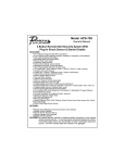
CONTENTS
THERMOSTATS. . . . . . . . . . . . . . . . . . . . . . 2
COOLING ONLY . . . . . . . . . . . . . . . . . . . .
COOLING AND HEATING . . . . . . . . . .
MANUAL CHANGEOVER . . . . . . . . . . .
COMPUTERIZED ELECTRONIC
THERMOSTAT . . . . . . . . . . . . . . . . . . .
FAN OPERATION SELECTION . . . . . .
START-UP . . . . . . . . . . . . . . . . . . . . . . . .
2
2
2
2
2
2
USER’S, MAINTENANCE
and
SERVICE INFORMATION
MANUAL
SYSTEM OPERATION. . . . . . . . . . . . . . . . . 3
MANUAL CHANGEOVER
THERMOSTAT . . . . . . . . . . . . . . . . . . . 3
ELECTRONIC THERMOSTAT . . . . . . . 3
MAINTENANCE . . . . . . . . . . . . . . . . . . . . . . 3
LUBRICATION . . . . . . . . . . . . . . . . . . . . .
FILTER CARE . . . . . . . . . . . . . . . . . . . . . .
REGISTERS . . . . . . . . . . . . . . . . . . . . . . .
COIL CARE . . . . . . . . . . . . . . . . . . . . . . . .
3
3
3
3
SINGLE PACKAGE
AIR CONDITIONER
TROUBLESHOOTING . . . . . . . . . . . . . . . . . 4
BEFORE CALLING A SERVICE-MAN . . . 4
PARTS INFORMATION . . . . . . . . . . . . . . 4
SOME EFFICIENCY DO’S AND DON’TS. 4
The manufacturer recommends that the “User” read all sections of this manual
and keep the manual for future reference.
Tested in accordance with:
66235-BUM-C-0313
66235-BUM-C-0313
C
ongratulations . . .
On your purchase of one of our Single Package Air Conditioning Units. This energy efficient system has been precision
designed, manufactured of high quality materials and has passed many vigorous inspections and tests to ensure years of satisfactory service.
This manual is meant to increase your understanding of your system, tells you how to operate it efficiently and how to obtain
the greatest measure of comfort at the lowest operating expense. Please read this manual thoroughly.
We appreciate your interest in our products and your decision to purchase our Single Package Unit. Enjoy your comfort.
THERMOSTATS - Your Key
to Comfort
Though thermostats may vary widely
in appearance, all are designed to
perform the same basic function - to
control the operation of your air
conditioning system.
Regardless of size or shape, each
thermostat will feature a temperature
indicator; a dial, arm or push button
for selection of the desired
temperature; a fan switch to choose
the indoor fan operation; and a
comfort switch for you to select the
system mode of operation.
The following illustrations and
discussion will aid you to determine
which type of thermostat you have
for your system. Follow the
applicable instructions in this manual
to obtain the maximum comfort with
a minimum of energy consumption.
COOLING ONLY
If your air conditioning system is
designed to provide only cooling,
with no capability for heating
operation, a cooling only thermostat,
with a manual, two-position “Cool”
and “Off” comfort switch is all that is
required for system operation.
Cooling and Heating
If your system has been designed to
allow both cooling and heating
operation, you may have either of
two types of thermostat. A manual
change-over type, or a computerized
electronic thermostats.
Manual Changeover
Manual changeover simply means
that the comfort switch must be
2
manually positioned every time you
wish to switch from the cooling to
heating or heating to cooling models
of operation.
even temperature distribution to all
conditioned spaces. The sound level
within the building will also remain
relatively constant.
Computerized Electronic Thermostat
FAN ONLY OPERATION:
The
computerized
electronic
thermostat is actually a sophisticated
electronic version of a manual
change-over type. This thermostat
includes features which allow “setback” temperature variations for
periods of sleep, or while you are
away during the day, and means
energy saving for you.
On moderate days, usually during
spring and fall, when neither heating
nor cooling is required, you may
want to run only the fan to ventilate,
circulate and filter the air in your
home or building.
The thermostat also features a digital
clock. If you have selected this type
of thermostat, a complete operating
instruction is provided by the
manufacturer with the thermostat.
Fan Operation Selection
A two-position fan switch allows you
to choose the type of operation of the
indoor fan.
AUTO
With the thermostat fan switch set to
“AUTO”, the fan will run intermittently
as required for either heating or
cooling. This position will provide the
lowest operating cost, and better
humidity
control
on
cooling
operation.
ON
CONTINUOUS FAN OPERATION:
With the thermostat fan switch set to
“ON”, the indoor fan will not shut-off.
However, the cooling and heating
systems will still operate as required
by room temperatures. This provides
continuous air filtering and more
Set the comfort control switch to
“OFF” and the fan switch to “ON”. Be
sure to return the switches to their
original
positions
for
normal
operation.
START-UP
The comfort control switch is
assumed to be in the “OFF” position.
If the main power supply to the unit is
off, turn the appropriate disconnect
switch to the “ON” position.
If a warning label is attached to the
disconnect switch, as shown below,
and if the power supply has been off
for 8 hours or longer, the disconnect
switch must be turned on 8 hours
before the thermostat is set to
operate the compressor.
IMPORTANT
IF POWER HAS BEEN OFF
FOR 8 HOURS OR LONGER,
DISCONNECT SWITCH
MUST BE TURNED ON 8
HOURS BEFORE THERMOSTAT IS SET TO “HEAT”,
“COOL” OR “AUTO”.
035-03095A
Johnson Controls Unitary Products
66235-BUM-C-0313
Please the system into operation as
follows:
1. Set temperature adjustment to
the desired temperature.
COOLING - The higher the setting, the lower the amount of
energy consumed. The National
Bureau of Standard recommends a setting of 78F.
When the indoor temperature
drops below the level indicated
by the temperature adjustment
setting, the system will start.
The heating system will operate and the indoor fan will circulate the heated, filtered air.
When the room temperature
rises to the setting selected,
the system will shutoff.
HEATING - The lower the setting, the lower the amount of
energy consumed. Federal
guidelines recommend a setting
of 65F or lower.
Whether heating or cooling, the fan
will continue to operate if the fan
switch was set in the “ON”
position.The “AUTO” setting on the
fan switch will allow the fan to shut
off when your system does.
NOTE: If your cooling and
heating temperature adjustments are separate, be sure to
set both.
Electronic Thermostat
2. After considering “Fan Operation
Selection” on page 2, select and
set the fan operation mode you
desire.
3. Move the comfort control switch
to the desired mode of operation
found on your particular thermostat.
SYSTEM OPERATION
Manual Changeover Thermostat
COOLING YOUR HOME-With the
comfort control switch in the “COOL”
position, the system will operate as
follows:
When the indoor temperature
rises above the level indicated
by the temperature adjustment
setting, the system will start.
The outdoor unit will operate
and the indoor fan will circulate
the cooled, filtered air. When
the room temperature is lowered to the setting selected,
the system will shut off.
HEATING YOUR HOME-If your
system includes a heating unit and
the comfort control switch is in the
“HEAT” position, the system will
operate as follows:
Johnson Controls Unitary Products
The
computerized
electronic
thermostat, when programmed, will
function automatically to operate the
system as follows:
When the indoor temperature rises
above the higher (COOL) setting, the
unit will operate and the indoor fan
will circulate the cooled, filtered air.
When the temperature is lowered to
the selected level, the system will
shut off. The indoor fan will either
shut off or run continuously,
depending upon your choice of fan
switch setting.
When the indoor temperature drops
below the lower (HEAT) setting, the
heating system will operate, and the
indoor fan will circulate the heated,
filtered air. When the indoor
temperature rises to the selected
setting, the system will shut off.
NOTE: The thermostat has a
built-in off-cycle timer to prevent the unit from operating
until the system pressures
have equalized.
MAINTENANCE
CAUTION: Prior to any of the
following maintenance procedures, shut off all power to the
unit.
LUBRICATION
Both the indoor blower motor and
outdoor fan motor are permanently
lubricated
and
requires
no
maintenance.
FILTER CARE
Single phase units are shipped
without a filter and is the
responsibility of the installer to
secure a filter in the return air
ductwork or install a filter/frame kit
(6MC54). A filter rack and filters are
standard on three phase units.
Filters must always be used and
must be kept clean. When filters
become dirt laden, insufficient air will
be delivered by the blower,
decreasing your units efficiency and
increasing operating costs and wearand-tear on the unit and controls.
Filters should be checked monthly
especially since the unit may be
used for both heating and cooling.
High velocity permanent filters may
be removed for cleaning. Remove
filters, vacuum or wash with a stream
of water directly from a faucet or
hose. Allow filters to dry and replace.
High velocity permanent filters
should last for many years. However,
if they ever need replacing, they
must be replaced with the same size
and type.
REGISTERS
Supply and return air registers must
be open when the unit is in
operation. Furniture must not block
airflow in or out of the registers.
COIL CARE
An annual check and cleaning, if
necessary, of the condenser coil
should be done. Clean any debris
and dirt from the outside coil face
with a brush being careful not to
damage the fins. If extremely dirty, a
hose can be used to wash the coil
from the inside out while brushing a
soapy solution on the outside.
3
TROUBLESHOOTING
BEFORE CALLING A SERVICEMAN:
A. Check thermostat setting and
insure thermostat is calling for
heat or cooling.
B.
Check thermostat for lint, dust, etc.
C.
Check fuses or circuit breakers.
D.
Check filters for excessive dust
accumulation and/or restriction.
PARTS INFORMATION
Contact your local Unitary Products
parts
distribution
center
for
authorized replacement parts.
SOME EFFICIENCY DO’S AND
DON’TS
DON’T heat or cool unused areas.
Reduce supply and return air flow to
a minimum in areas which are not
living spaces (storage rooms,
garaged, basements, etc.).
DON’T be a “thermostat jiggler”.
Moving your thermostat setting will
not make your system heat or cool
any faster. Adjust your thermostat to
a comfortable setting and leave it
there.
DON’T restrict air circulation. Placing
furniture, rugs, etc. in such away that
they interfere with air vents will make
your system work harder to achieve
a comfortable temperature level.
This requires more energy, which
means greater cost to you.
DON’T heat or cool when you are
away. If you are going to be away for
a day or more, readjust your
thermostat
accordingly.
Your
furniture is far less demanding than
you are when it comes to comfort
levels. However, don’t expect the
system to restore comfort conditions
immediately upon returning home. It
will take a little time.
DON’T locate lamps or other heatproducing appliances (radios, TV’s,
heaters,
etc.)
near
your
thermostat.The heat from these
items will give your thermostat “false
information” about the temperature
in the room.
moderation in temperature selection
will save energy.
DO turn on your kitchen exhaust fan
when cooking and your bathroom
exhaust fan when showering. Also,
make sure your clothes dryer is
properly vented. If these items are
neglected, an excess heat and
humidity condition may be created,
causing your air conditioning system
to run longer.
DO set your thermostat a few
degrees lower than normal several
hours before entertaining a large
group of people in a relatively small
area. People give off a considerable
amount of heat and moisture in a
closed area.
DO keep drapes and Venetian blinds
closed when practical. These items
provide insulation against heat loss/
gain.
DO contact a qualified serviceman to
make repairs or adjustments to your
system. He has been trained to
perform this service.
DO select a comfortable thermostat
setting, but keep in mind that
Subject to change without notice. Printed in U.S.A.
Copyright © 2013 by Johnson Controls, Inc. All rights reserved.
York International Corporation
5005 York Drive
Norman, OK 73069
66235-BUM-C-0313
Supersedes: 66235-BUM-B-0709