1
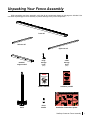
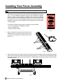
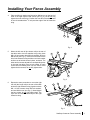
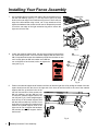
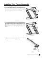
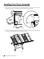
SawStop
®
Contractor Fence Assembly
OWNER’S MANUAL
Model CNS-SFA
Warranty
SawStop warrants to the original retail purchaser of the Contractor Fence Assembly accompanying this manual
that the fence assembly will be free from defects in material and workmanship for ONE YEAR from the date of
purchase. This warranty does not apply to defects arising from misuse, abuse, negligence, accidents, normal wearand-tear, unauthorized repair or alteration, or lack of maintenance.
Please contact SawStop to take advantage of this warranty. If SawStop determines the fence assembly is
defective in material or workmanship, and not due to misuse, abuse, negligence, accidents, normal wear-andtear, unauthorized repair or alteration, or lack of maintenance, then SawStop will, upon proof of purchase and at
its expense, send replacement parts to the original retail purchaser necessary to cure the defect. Alternatively,
SawStop will repair the fence assembly provided it is returned to SawStop, shipping prepaid, within the warranty
period.
SawStop disclaims any and all other express or implied warranties, including merchantability and fitness for a
particular purpose. SawStop shall not be liable for death, injuries to persons or property, or incidental, consequential,
contingent or special damages arising from the use of the saw.
This warranty gives you specific legal rights. You may have other rights which vary from state to state.
Safety
1.
You must install a rip fence before using your contractor saw. Attempting to use the saw without the rip fence
could result in serious personal injury.
2.
Always use a rip fence when making rip cuts. Never perform a ripping operation freehand or a serious injury
may result.
3.
Always use a push stick or push block when your hand comes within 6 inches of the blade. Attempting to use
the rip fence for narrow cuts without a push stick or push block could result in a serious personal injury.
4.
Do not use the miter gauge when making rip cuts.
5.
While making bevel cuts, use the fence only on the right side of the saw blade to prevent the blade from
possibly contacting the fence. The brake will activate if the spinning saw blade comes into contact with the
aluminum in the rip fence.
Unpacking Your Fence Assembly
While unpacking your fence assembly verify that all the components shown on this page are included. Use
care when unpacking your fence assembly to prevent damage to any of the components.
front rail
left rear rail
right rear rail
material
support shelf
large
storage
hook
small
storage
hook
(two)
(two)
Hardware Pack
#3
Installing the Fence Rails Assembly
Hardware for Steps 1-11
SawStop
®
Sa
wS
to
p
Square Head Screws, M8 x 20
16
(10 + 1 extra)
Contractor Fence Assembly
OWNER’S MANUAL
Lock Washers, M8
(22 + 1 extra)
Hex Nuts, M8
(18 + 1 extra)
SawStop
Hex Screws, M8 x 16
(8 + 1 extra)
owner’s manual
17
18
Carriage Bolts,
20
M8 x 20 (4)
19
hardware pack #3
®
SawStop Service Department
503-682-6222
Installing Your SawStop Contractor Fence Assembly
www.sawstop.com
© SawStop, LLC
Installing the Fence Rails
Assembly
• Place an M8 lock washer 17 and thread an M8 hex nut 18 on
the back of each of the eight square head screws, but do not fully
tighten the nuts at this time. Position the front rail so that the left
end of the rail extends about 3 ⁄4 inch past the edge of the left
extension wing.
• Remove eight M8 x 20 square head screws 16 from the
hardware pack and slide the square head of each screw into the
slot along the rear edge of the front rail.
• Locate the front rail, the left and right rear rails, and hardware
pack #3. All of the hardware needed to install the rails is located
on hardware pack #3. In order to easily identify the hardware
used in each of the following steps, the different pieces of
hardware are numbered on the hardware pack and in the figures.
If you are missing hardware pack #3 or any of the other fence
assembly components, call the SawStop Service Department at
503-682-6222 for replacements.
Hardware Pack
Hardware for Steps 1-10
Lock Washers, M8
(22 + 1 extra)
1
Hex Nuts, M8
(18 + 1 extra)
Hex Screws, M8 x 16
(8 + 1 extra)
19
16
SawStop
Square Head Screws, M8 x 20
16
(10 + 1 extra)
1. two 13 mm wrenches
2. a level or straight-edge
3. a rubber hammer or mallet
17
#3
Installing the Fence Rails
You will also need the following tools
to complete the fence assembly:
19
17
18
Carriage Bolts,
20
M8 x 20 (4)
19
17
19
• Adjust the position of each square head screw so that all eight
screws align with the corresponding mounting holes in the front
edge of the table top and extension wings. Position the front rail
against the edge of the table with the eight screws
extending through their corresponding mounting holes.
Make sure the rulers on the front rail are facing up.
16
2
3
• Repeat the same procedure to mount the right rear rail (the
longer rail) to the rear of the table and to the right extension
wing. Again use three M8 x 16 hex screws 19 , three M8 lock
washers 17 , and one M8 hex nut 18 . Hand tighten the hex
screws; do not fully tighten them. The right rear rail should
extend beyond the right extension wing.
19
straight-edge
17
18
4
• Locate the material support shelf, the two large storage hooks,
the two small storage hooks, and hardware pack #3. All of the
hardware needed to assemble the material support shelf is
located on hardware pack #3. Take the material support shelf
and insert two M8 x 20 square head screws 16 into the holes on
one end. Place an M8 lock washer 17 and a M8 hex nut 18 on
the back of each screw, but do not tighten the nuts.
19
17
19
16
17
Hardware Pack
#3
Installing the Fence Rails
17
Hardware for Steps 1-10
17
SawStop
18
fence
fence
handle
• Mount the left rear rail (the shorter rail)
to the rear of the table and to the left extension
wing using three M8 x 16 hex screws 19 , three
M8 lock washers 17 , and one M8 hex nut 18 . Insert one hex
screw into the hole in the extension wing and then use a lock
washer and hex nut to hold the screw in place, as shown. The
other two hex screws thread into corresponding holes
in the cast iron table. Place a lock washer on each
screw before threading them into the holes. Hand
tighten the hex screws; do not fully tighten them.
5
Square Head Screws, M8 x 20
16
(10 + 1 extra)
Lock Washers, M8
(22 + 1 extra)
17 18
6
• Use a straight-edge to level the rear edge of the left extension
wing to the cast iron table top. You may have to pull up or push
down on the outer edge of the extension wing to level it. Once the
rear edge of the left extension wing is level, use 13 mm
wrenches to fully tighten the hardware that mounts the
left rear rail. Repeat this process to level the rear edge
of the right extension wing and secure the right rear rail.
7
Hex Nuts, M8
(18 + 1 extra)
8
Hex Screws, M8 x 16
(8 + 1 extra)
19
18
17
18
Carriage Bolts,
20
M8 x 20 (4)
installation instructions poster
SawStop Contractor Fence Assembly Installing Your Fence Assembly
Note: Your contractor saw must be fully assembled before installing the fence assembly.
1.
Locate the front rail, the left and right rear rails, and hardware pack #3 (see
Fig. 1). All of the hardware needed to install the rails is located on hardware
pack #3. In order to easily identify the hardware used in each of the following
steps, the different pieces of hardware are numbered on the hardware pack and
in the figures. If you are missing hardware pack #3 or any of the other fence
assembly components, call the SawStop Service Department at 503-682-6222
for replacements.
Hardware Pack
#3
Installing the Fence Rails Assembly
Hardware for Steps 1-11
S
a
w
S
to
p
Square Head Screws, M8 x 20
16
(10 + 1 extra)
Lock Washers, M8
(22 + 1 extra)
You will also need the following tools to complete the fence assembly:
• two 13 mm wrenches (or adjustable wrenches)
• a level or straight-edge
• a rubber hammer or mallet
Hex Nuts, M8
(18 + 1 extra)
Hex Screws, M8 x 16
(8 + 1 extra)
19
17
18
Carriage Bolts,
20
M8 x 20 (4)
Fig. 1
2.
Remove eight M8 x 20 square head screws from the
hardware pack and slide the square head of each
screw into the slot along the rear edge of the front rail
(see Fig. 2).
slot
end view
16
16
Fig. 2
3. Adjust the position of each square head screw so that all eight screws align with the corresponding mounting
holes in the front edge of the table top and extension wings (see Fig. 3). Position the front rail against the edge
of the table so that the eight screws extend into their corresponding mounting holes. Make sure the rulers on
the front rail face up.
Fig. 3
SawStop Contractor Fence Assembly
Installing Your Fence Assembly
4.
Place an M8 lock washer and thread an M8 hex nut on the back of
each of the eight square head screws (see Fig. 4), but do not fully
tighten the nuts at this time. Position the front rail so that the left end
of the rail extends about 3⁄4 inch past the edge of the left extension
wing.
17
18
Fig. 4
5.
Mount the left rear rail (the shorter rail) to the rear of
the table and to the left extension wing using three
M8 x 16 hex screws, three M8 lock washers, and one
M8 hex nut (see Fig. 5). Insert one hex screw into the
hole in the extension wing and then use a lock washer
and hex nut to hold the screw in place, as shown. The
other two hex screws thread into corresponding holes
in the cast iron table. Place a lock washer on each
screw before threading them into the holes. Hand
tighten the hex screws; do not fully tighten them.
19
17
19
17
19
17
18
Fig. 5
6.
Repeat the same procedure to mount the right
rear rail (the longer rail) to the rear of the table
and to the right extension wing. Again use three
M8 x 16 hex screws, three M8 lock washers,
and one M8 hex nut (see Fig. 6). Hand tighten
the hex screws; do not fully tighten them. The
right rear rail should extend beyond the right
extension wing.
19
19
19
17
17
17 18
Fig. 6
SawStop Contractor Fence Assembly Installing Your Fence Assembly
7.
Use a straight-edge to level the rear edge of the left extension wing to
the cast iron table top (see Fig. 7). You may have to pull up or push
down on the outer edge of the extension wing to level it. Once the rear
edge of the left extension wing is level, use 13 mm wrenches to fully
tighten the hardware that mounts the left rear rail. Repeat this process
to level the rear edge of the right extension wing and to secure the
right rear rail to the saw.
straight-edge
Fig. 7
8. Locate the material support shelf, the two large storage hooks and the
two small storage hooks. Take the material support shelf and insert two
M8 x 20 square head screws from hardware pack #3 into the holes on one
end. Loosely place an M8 lock washer and a M8 hex
Hardware Pack # 3
nut on the back of each screw, but do not tighten the
nuts (see Fig. 8).
Installing the Fence Rails Assembly
16
17
Hardware for Steps 1-11
Sa
w
St
op
18
Square Head Screws, M8 x 20
16
(10 + 1 extra)
Lock Washers, M8
(22 + 1 extra)
Hex Nuts, M8
(18 + 1 extra)
Hex Screws, M8 x 16
(8 + 1 extra)
19
17
18
Carriage Bolts,
20
M8 x 20 (4)
Fig. 8
Position the material support shelf between the front rail and the right rear rail by sliding the heads of the two
square head screws into the slot on the right end of the front rail until the holes in the rear of the material
support shelf line up with the holes in the
rear rail. Use two M8 x 16 hex screws, two
M8 lock washers, and two M8 hex nuts
to mount the material support shelf to the
rear rail (see Fig. 9). Use a straight-edge to
level the top of the material support shelf
with the cast iron table top. Use two 13 mm
18
wrenches to fully tighten the hardware that
mounts the material support shelf to the
17
right rear rail. Do not tighten the hardware
that mounts the material support shelf
to
19
30
the front rail.
45
9.
SawStop
10” Contractor Saw
Fig. 9
SawStop Contractor Fence Assembly
Installing Your Fence Assembly
10. The two large storage hooks mount to the material support shelf,
and can be used to store the fence when not in use. Use two M8
x 20 carriage bolts, two M8 lock washers, and two M8 hex nuts to
mount the hooks to the right side of the material support shelf (see
Fig. 10). Fully tighten the nuts using a 13 mm wrench.
17
18
20
Fig. 10
11. The two small storage hooks also mount to the material support
shelf, and can be used to store the miter gauge when not in use.
Use two M8 x 20 carriage bolts, two M8 lock washers, and two
M8 hex nuts to mount the hooks to the left side of the material
support shelf (see Fig. 11). Fully tighten the nuts using a 13 mm
wrench.
17
20
18
Fig. 11
12. Locate the fence and red fence handle. Thread the handle into the
cam lock on the front of the fence (see Fig. 12).
S
aw
St
op
thread the
handle into
the cam lock
Fig. 12
SawStop Contractor Fence Assembly Installing Your Fence Assembly
13. Position the fence on the table and to the right of the blade. Make sure the clamp at the rear of the fence
engages the rear rail (see Fig. 13), and that the front of the fence engages the front rail.
! WARNING
WARNING
and parts
Moving belts or crush.
cut
can pinch,
te with
Do not opera
open.
belt guard
For your own safety, read the
instruction
manual before operating this saw.
SawStop
1. Wear eye protection.
Use the blade guard and spreader for every
operation for which it can be used, including all
through sawing.
3. Keep hands out of the line of the saw blade.
4. Use a push-stick when required.
5. Know how to reduce the risk of kickback.
6. Do not perform any operation freehand.
7. Never reach around or over the saw blade.
8. Never try to test fire the brake system.
9. Never adjust the position of the brake cartridge
while the blade is spinning.
10. Do not try to disable the brake system.
11. Unplug the saw before changing the blade,
changing the brake cartridge or servicing.
12. Do not connect the motor directly to a power
supply.
13. Use the bypass switch only when necessary.
14. Do not expose to rain or use in damp locations.
15. Do not put your hands inside or underneath the
cabinet while the blade is spinning.
®
10¨ Contractor Saw
Model No. CNS 175
Serial No. C074012345
Electrical / Electricidad / Électricité
115/230 Volts, 60 Hz
15/7.5 Amps
1 Phase
c
SawStop, LLC
1.75 HP
3500 RPM
®
US
175370
www.sawstop.com
Made in Taiwan
TCP
engage
fence clamp
on rear rail
Fig. 13
Sa
w
St
op
14. To determine the final placement of the front rail, raise the saw blade and position the fence so that the left side
of the fence rests against the right side of the saw blade (see Fig. 14).
Fig. 14
SawStop Contractor Fence Assembly
Installing Your Fence Assembly
15. With the fence unclamped and still against the right side of the saw blade, gently tap one end of the front rail
with a rubber hammer or mallet to move the rail to the right or left until the cursor on the right fence scale is
aligned with zero on the underlying ruler (see Fig. 15). Be careful to tap the front rail gently or the plastic cap
at the end of the rail may be damaged. Once the right fence scale reads zero the front rail is in the correct
position.
50
0
1
2
60
40
30
20
0
10
10
4
3
60
70
80
90
10 0
5
10
20
30
right fence scale
should read zero
Fig. 15
16. Use a straight-edge to level the front edge of the left extension wing to the cast iron table top (see Fig. 16).
You may have to pull up or push down on the outer edge of the extension wing. You also may need to remove
the fence from the table to provide clearance for the straight-edge. Be careful not to change the position of the
front rail. Once the front edge of the left extension wing is level, use a 13 mm wrench to fully tighten the nuts in
the front rail that extend through the left extension wing and the table top. Repeat this process to level the front
edge of the right extension wing and the material support shelf and then fully tighten the remaining nuts in the
front rail.
straight-edge
45
30
0
15
SawStop
10” Contracto
r Saw
Fig. 16
Congratulations, your fence assembly is now
installed and your saw is ready to use.
SawStop Contractor Fence Assembly Using Your Rip Fence
The rip fence included with your contractor saw is
used to guide material parallel to the blade when
you make rip cuts (cuts that are length-wise along
the grain of the wood). The fence must always be
used when making rip cuts. The fence also allows
you to precisely set the width of your rip cuts. When
not in use, you can store the fence on the two fence
storage hooks mounted to the material support shelf
(see Fig. 17)
rip fence in
storage location
Fig. 17
To use the rip fence, begin by placing it on the
fence rails so that the clamp at the rear of the fence
engages the rear rail and so that the front of the
fence engages the front rail. You can use the fence
on either the left or right side of the blade for nonbevel cuts. If you plan to make bevel cuts, use the
fence only on the right side to prevent the blade from
possibly contacting the fence. After placing the fence
on the rails, lift the red handle up to the unlocked
position (see Fig. 18) and slide the fence to the left
or right until the distance between the blade and the
fence is approximately equal to the desired width of
cut.
fence handle in the
unlocked position
Fig. 18
The precise width of cut is shown by the indicator
lens on the front of the fence (see Fig. 19). The
lens on the left indicates the width of cut when the
fence is on the left side of the blade. The lens on
the right indicates the width of cut when the fence
is on the right side of the blade. Each indicator lens
in positioned above a ruler on the front rail. Each
lens has a red cursor line that indicates the precise
width of cut. To read the width of cut, look down at
the cursor line. The mark on the ruler that is directly
below the cursor line is the width of cut.
Adjust the position of the fence until the cursor is
directly over the desired width of the cut. Once the
fence is in the correct position, push the red locking
handle down to the locked position. The fence is
now locked in place and ready for use.
SawStop Contractor Fence Assembly
left indicator
right indicator
Fig. 19
Adjusting Your Rip Fence
The fence should be securely locked to the rails when the red handle is in the downward locked position. If
the fence locks tightly and cannot be easily moved, no further adjustment is necessary. However, if the fence
does not lock tightly, or if the fence locks too tightly, you will need to adjust the clamping force applied by the
fence.
If adjustment is necessary, the
clamping force is set by the 10 mm
hex nut in the end of the fence (see
Fig. 20). To increase the clamping
force, turn the hex nut clockwise
with a 10 mm socket. To decrease
the clamping force, turn the hex
nut counter-clockwise. Lock the
fence in place with the red handle
and verify that the fence is locked
securely to the rails. If further
adjustment is necessary, repeat the
steps above.
use a 10 mm socket to adjust
the fence clamping force
Fig. 20
use a 5 mm hex key to adjust
the fence parallelism
The fence must be parallel to the cutting
surface of the blade to make an accurate rip
cut. Use the following procedure to check if
the fence is parallel to the blade.
Slide the fence until the left face of the
fence is adjacent to one of the miter slots
and clamp it in place (see Fig. 21). If the
left face is parallel to the miter slot, then no
further alignment is needed. If the left face
is not parallel to the miter slot, unclamp
the fence and then reclamp it to see if it
straightens out.
If the fence is still not parallel to the miter
slot, unclamp the fence and loosen the two
socket head screws in the top of the fence
with a 5 mm hex key (see Fig. 21). Then
align the side of the fence with the miter
slot, clamp the fence in place and re-tighten
the screws. The fence is now set parallel to
the cutting surface of the blade.
adjustment
bolt
Fig. 21
SawStop Contractor Fence Assembly Contractor Fence Rails Assembly Exploded View
2
3
8
10
2
10
10
9
2
3
10
0
6
15
30
10”
Saw
Co
ntr
Sto
act
or S
p
aw
5
2
13
14
3
4
3
13
2
11
1
3
2
3
1
12
13
7
10 SawStop Contractor Fence Assembly
6
13
2
Contractor Fence Rails Assembly Parts List
No.
Description
Part No.
Qty.
Contractor Fence Rails Assembly (includes items 1-14)
SFA-07-000
1
1
M8x1.25x20 Square Head Screw
SFA-07-001
10
2
M8.2x15.4 Lock Washer
SFA-07-002
22
3
M8x1.25 Hex Nut
SFA-07-003
18
4
Front Rail (includes items 5-7)
SFA-07-004
1
5
Left Front Rail End Cap
SFA-07-005
1
6
M4x8 Button Head Philips Sheet Metal Screw
SFA-07-006
4
7
Right Front Rail End Cap
SFA-07-007
1
8
Left Rear Rail
SFA-07-008
1
9
Right Rear Rail
SFA-07-009
1
10
M8x1.25x16 Hex Screw
SFA-07-010
8
11
Material Support Shelf
SFA-07-011
1
12
Large Storage Hook
SFA-07-012
2
13
M8x1.25x20 Carriage Bolt
SFA-07-013
4
14
Small Storage Hook
SFA-07-014
2
N/A
Contractor Fence Assembly Owner’s Manual
SFA-07-046
1
N/A
Installation Instructions Poster
SFA-07-047
1
N/A
Hardware Pack #3
SFA-07-048
1
Accessories
SawStop Contractor Fence Assembly 11
Contractor Fence Assembly Exploded View
29
27
30
28
19
SawStop
24
26
2
22
17
1
23
14
25
13
12
18
21
3
6
5
20
16
8
15
10
11
4
7
12 SawStop Contractor Fence Assembly
9
Contractor Fence Assembly Parts List
No.
Description
Part No.
Qty.
Contractor Fence Assembly (includes items 1-30)
SFA-07-015
1
1
Fence Tube
SFA-07-016
1
2
M6x1.0x10 Socket Head Socket Screw
SFA-07-017
2
3
Fence Head
SFA-07-018
3
4
Handle
SFA-07-019
1
5
Cam Lock
SFA-07-020
1
6
Handle Axle
SFA-07-021
1
7
M6x1.0x20 Socket Head Socket Screw
SFA-07-022
2
8
Front Rail Clamp Pivot Bracket
SFA-07-023
1
9
Large Front Rail Glide
SFA-07-024
2
10
Small Front Rail Glide
SFA-07-025
2
11
M4x8 Button Head Philips Sheet Metal Screw
SFA-07-026
4
12
Position Indicator Lens
SFA-07-027
2
13
M5.3x12x1 Washer
SFA-07-028
2
14
M5x0.8x6 Button Head Philips Screw
SFA-07-029
2
15
M8x40 Spring Pin
SFA-07-030
1
16
Fence Rod
SFA-07-031
1
17
Fence Spring Retaining Plate
SFA-07-032
1
18
Rear Fence Clamp
SFA-07-033
1
19
Rear Clamp Pivot Bracket
SFA-07-034
1
20
M4x5 Flat Head Shoulder Screw
SFA-07-035
1
21
Rear Glide Roller
SFA-07-036
1
22
M6.6x13x1 Washer
SFA-07-037
1
23
Clamp Release Spring
SFA-07-038
1
24
Clamp Adjustment Nut
SFA-07-039
1
25
M4.3x12x1 Washer
SFA-07-040
2
26
M4x0.7x10 Button Head Philips Screw
SFA-07-041
2
27
Fence End Cap
SFA-07-042
1
28
M6x40 Spring Pin
SFA-07-043
1
29
M4x16 Button Head Philips Sheet Metal Screw
SFA-07-044
4
30
Fence Label
SFA-07-045
1
SawStop Contractor Fence Assembly 13
SawStop, LLC
9564 S.W. Tualatin Road
Tualatin, Oregon 97062
www.sawstop.com
Main Phone - (503) 570-3200
Service - (503) 682-6222
Fax - (503) 570-3303
Email: [email protected]
Updates of this manual may be available at www.sawstop.com.
Copyright SawStop, LLC
All Rights Reserved.
December 2007