1
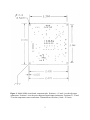
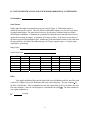
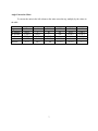
USER’S MANUAL
MODEL 84800 SIGNAL CONDITIONER
Serial no. ____________
Applied Geomechanics Inc.
1336 Brommer St.
Santa Cruz, CA 95062 USA
Tel 831/462-2801
Fax 831/462-4418
e-mail: [email protected]
www.geomechanics.com
© 2005 Applied Geomechanics Inc.
Manual no. B-97-1001, Rev. B
Printed in USA
1. INTRODUCTION
Your Model 84800 Signal Conditioner is a high-precision, low-noise printed circuit
assembly designed to operate Applied Geomechanics Miniature Tilt Sensors, Series 755, 756 and
757. In addition, it is an effective and reliable signal conditioner for electrolytic tilt sensors made by
other manufacturers.
The DC-powered Model.84800 generates the AC excitation necessary to operate the tilt
sensor, then demodulates, amplifies and low-pass filters the signal into high-level analog voltage
outputs. Single-ended (ground referenced) and differential (not ground referenced) outputs are both
provided. Model 84800 also takes temperature readings from a National Semiconductor LM35
temperature sensor mounted on the circuit board. Output is a single-ended analog voltage
proportional to temperature in degrees Celsius.
This user’s manual presents performance specifications for your signal conditioner, explains
how to make connections, and gives the scale factors for the sensor/signal conditioner combinations
delivered with your order.
2. SPECIFICATIONS
General specifications for the Model 84800 Signal Conditioner are listed below. Appendix
B contains custom specifications for your unit.
Output Range (Tilt):
Single-ended: +8 volts to -5 volts DC (typical)
Differential: +10 volts to -10 volts DC (usable range)
Output Range (Temperature):
Single-ended only: -0.40 volts to +1.00 volt DC
Scale Factors:
Tilt: See Appendix B
Temperature: 0.1º C/mV
Tilt Output Filter:
2-pole Butterworth low-pass filter. Roll-off = 12 dB per
octave. See Appendix B for your filter time constant.
Output Impedance:
270 ohms, short circuit and surge protected
Power Requirements:
peak-to-peak
Environmental:
.
Mounting:
+8 to +17 VDC @ 10 mA typical; 250 mV
ripple max.
-25º to +70ºC operational, -30º to +100ºC storage. 0 to
90% humidity, noncondensing
Four 0.12 inch (3.05mm) dia. holes on 2.30 inch (58.4
mm) centers
1
Dimensions:
2.47 x 2.47 x 0.63 inches (62.7 x 62.7 x 16 mm)
Weight:
0.75 oz (21 g)
Materials:
Fiberglass printed circuit board
3. MAKING CONNECTIONS
Circuit board geometry and connector locations are shown in Figure 1. Your tilt sensor
connects to the board at the pins marked (−), E and (+). The tilt sensor wires corresponding to these
positions are defined in the user’s manual for your tilt sensor.
Power input and signal output connections are made at the pins marked 1, 2, 3, 4, 5 and 6
(Figure 1). Pin designations and wire color coding of the connector assembly shipped with your
signal conditioner are defined in the table below. For additional information on recording your
signal, see Appendix B. WARNING! Do not connect your tilt sensor to pins 1-6. Sensor damage
not covered by the warranty will result!
Pin
Function
Wire Color
1
2
3
4
5
6
DC power in
Signal ground
Power ground
+Tilt out
- Tilt out
Temperature out
red
white
black
green
blue
yellow
In the standard Model 84800 the temperature sensor is soldered to the circuit board at the
“X” locations T1, T2 and T3 (Figure 1). If you are using a temperature sensor that plugs into the
circuit board, the wire colors corresponding to the T1, T2 and T3 positions can be found in the user’s
manual for your tilt sensor package.
4. GROUNDING AND TRANSIENT PROTECTION
Signal and power ground (pins 2 and 3, Figure 1) are common on the circuit board.
However, if you plan to measure single-ended tilt or temperature at a distance more than several
meters away from the board, it is a good idea to measure the tilt signal (pin 4) and the temperature
signal (pin 6) with reference to a wire connected to signal ground (pin 2). Run a separate power
ground wire to your power supply from pin 3. Do not connect signal and power grounds at the
power supply. With this wiring arrangement no current flows in your signal ground wire. The
output voltage should therefore be the same at your measurement point as on the Model 84800
circuit board.
2
Figure 1. Model 84800 circuit board, component side. Positions (−), E and (+) are the tilt sensor
connections. Positions 1-6 are the power input and signal output connections. Positions T1, T2 and
T3 are the temperature sensor connections. Dimensions are in inches (1 inch = 25.4 mm).
3
Measuring your tilt signal differentially (pin 4 with respect to pin 5) eliminates the ground
reference and also prevents a voltage shift between signal conditioner and measurement point.
Each of pins 1 through 6 is connected to the mounting hole in the lower left corner of the
board (Figure 1) through variable-resistance type transient surge absorbers. For maximum
protection against high-voltage transients, this corner of the board should be earthed to a grounding
rod, pipe or other metal object that is driven into the earth.
5. INITIAL CHECK OUT PROCEDURES
You can verify that your system is working properly by performing the following simple test:
1. Connect your tilt sensor to your signal conditioner at pins (−), E and (+).
2. Connect DC power and power ground to your signal conditioner at pins 1 and 3.
3. Use a voltmeter to read temperature between pins 6 and 2. Verify that the indicated temperature
corresponds to your actual ambient temperature (room temperature ~ 20ºC).
4. Use a voltmeter to read single-ended tilt output between pins 4 and 2. Verify that the output
voltage range corresponds to that indicated in the specifications above as you tilt your sensor
through its full angular range. The positive tilt output should be more than +5 volts DC.
5. User a voltmeter to read differential tilt output between pins 4 and 5. Verify that the output
voltage range is at least as great as that indicated in the specifications above as you tilt your
sensor through its full angular range.
If your results are not consistent with the specified performance, check to be sure that the
signal conditioner is receiving power in the specified voltage range and that all connections are
good. If power and connections are good, but you are still having problems, call Applied
Geomechanics Inc. in California for technical assistance at (408) 462-2801.
WARNING! Never use an ohmmeter to check your tilt sensor. Ohmmeters operate with
direct current (DC). Applying DC power to the tilt sensor will cause permanent damage that is not
covered by the warranty.
6. CONVERTING OUTPUT READINGS TO TILT ANGLES AND TEMPERATURES
The signal conditioner outputs are quickly converted to tilt angles and temperatures by
multiplying the voltage readings by the scale factors supplied in Appendix B. For example, if the
scale factor is 0.100 degrees/volt and the voltage output reading is +0.152 volt, then the tilt angle is
+0.0152 degree from sensor null. Similarly, a temperature output of 210 millivolts multiplied by
the scale factor 0.1ºC/mV equals a temperature of 21ºC.
4
7. MAINTENANCE AND TROUBLESHOOTING
Keep your signal conditioner clean, dry and away from extremes of heat and cold. Water is
the enemy of operating circuits. If the signal conditioner becomes wet while powered up, corrosion
and damage will quickly follow. Water damage to the circuit voids the warranty!
If there is no output when you have connected the signal conditioner to power and to a tilt
sensor, check to make sure that all connectors are securely attached. Failure to obtain an output
signal typically results from a broken wire or connection.
If the output is stuck at one end of the output range, the tilt sensor may simply be tilted off
scale. Slowly rotate the sensor back and forth to check this possibility. The tilt output should pass
through zero volts as you move the sensor through its null (level) position. If the output still does
not change, a sensor wire may be broken. WARNING! Do not test the tilt sensor with an ohmmeter,
permanent damage will result!
Please call Applied Geomechanics for assistance if you have not solved the problem after
performing the checks outlined above.
A. WARRANTY AND ASSISTANCE
Applied Geomechanics Model 84800 Signal Conditioner is warranted against defects in
materials and workmanship for one year from the date of delivery. We will repair or replace (at our
option) products that prove to be defective during the warranty period provided they are returned
prepaid to Applied Geomechanics Inc. No other warranty is expressed or implied. The warranty is
void if the equipment is damaged by water or high-voltage transients. After expiration of the
warranty, AGI will repair the equipment at its factory for parts and labor charges. Products returned
after warranty expiration should be accompanied by a purchase order to cover repair costs. Applied
Geomechanics Inc. is not liable for consequential damages.
THE REMEDIES PROVIDED HEREIN ARE THE BUYER'S SOLE AND EXCLUSIVE
REMEDIES. AGI SHALL NOT BE LIABLE FOR ANY DIRECT, INDIRECT, SPECIAL,
INCIDENTAL OR CONSEQUENTIAL DAMAGES, WHETHER BASED ON CONTRACT,
TORT OR ANY OTHER LEGAL THEORY.
5
B. CUSTOM SPECIFICATIONS FOR YOUR MODEL 84800 SIGNAL CONDITIONER
Serial number:
Scale Factors
Single-ended tilt output is measured between pins 4 and 2 (Figure 1). Differential output is
measured between pins 4 and 5. The scale factor for differential output is one half the scale factor
for single-ended output. The scale factors below are for tilt sensors calibrated with your Model
84800 Signal Conditioner. Calibrations are performed by tilting the sensor through a known set of
angles and measuring the output. A minimum of 10 steps are taken. Scale factors are the slope of
the linear regression line through the data. Nonlinearity is the maximum deviation of any point from
the regression line, divided by the calibration span (±0.5 degree angular range = 1.0 degree span),
expressed as a percentage.
Range Units:
Scale Factor Units:
Sensor S/N
Temp. (ºC)
Range (±)
Scale Factor
Linearity
Single-ended
Differential
Filter
Your signal conditioner filters the tilt signal with a two-pole Butterworth low-pass filter with
a roll-off of 12 dB per octave (40 dB/decade) above the corner frequency. The time constant τ for
the filter is listed below. After an instantaneous step, the output settles to 98% of its final value after
four time constants. Corner or cutoff frequency is calculated as fc = 1/(2 πτ). The time constant for
your signal conditioner is:
τ =
seconds
6
Angle Conversion Chart
To convert the units in the left column to the units across the top, multiply by the values in
the table.
degrees
arc minutes
arc seconds
µradians
mm/meter
inches/ft
degrees
1
0.0167
2.78E-4
5.73E-5
0.0573
4.775
arc minutes
60
1
0.0167
3.44E-3
3.44
286.5
arc seconds
3600
60
1
0.2063
206.3
17,189
7
µradians
17453
291
4.85
1
1000
83,333
mm/meter
17.45
0.291
4.85E-3
0.001
1
83.333
inches/ft
0.209
3.49E-3
5.82E-5
1.20E-5
0.0120
1