1
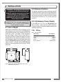
Manufacturers of Wireless
Weighing Systems
LSI Wireless
Gateway System
(Applies to: LSI Gateway series GS220 to GS224 and GS series sensors)
INSTALLER AND USER’S MANUAL
!
WARNING! The LSI Wireless Gateway system is designed to aid in the collection
of information and is in no way a substitute for safe operating practice.
!
WARNING! Carefully read and understand this manual before proceeding.
GM22X-XX_ENG_ rev 20130717
www.loadsystems.com
BEFORE PROCEEDING
Read and understand the following:
For your safety and that of the people that come
into contact with LSI products, understand the
significance of the instructions included in this
guide, respect all laws and regulations and comply
with applicable standards.
Pay particular attention to items bearing the alert
symbol ! and the following words:
WARNING!
!
Warning: this denotes an instruction that if not
complied with may lead to serious injury or death.
!
CAUTION!
Caution: this denotes an instruction that if not
complied with may lead to product failure or
property damage.
!
IMPORTANT!
Important: this denotes an instruction that if not
complied with may lead to product performance
issues.
!
WARNING! The system must be installed
in compliance with LSI instructions and
using LSI supplied components only. Failure
to install all parts, or replacing parts or
components with parts or components not
supplied by LSI, may lead to system failure,
serious injury or death.
2
The GS22X-XX Series Gateways
TABLE OF CONTENTS
1. INTRODUCTION.............................. 4
1.1 OVERVIEW....................................... 4
2.INSTALLATION................................ 5
2.1 LINE OF SIGHT................................ 5
2.2 ANTENNA POSITION...................... 5
2.3 LSI GATEWAY POWER SUPPLY..... 5
5.LSI PRODUCT LIMITED WARRANTY APRIL 1ST, 2013........................... 12
5.1 LIMITED WARRANTY................... 12
5.2 WARRANTY SERVICES
PROCEDURES............................... 12
5.3 EXCLUSION OF OTHER
WARRANTIES................................ 12
2.3a Wiring...................................................5
5.4 EXCLUSION................................... 13
2.4 LSI WM CONFIGURATOR............... 6
5.5 LIMITATION OF LIABILITY............ 13
2.5 PC INSTALLATION.......................... 6
5.6 RECOMMENDED PRACTICES..... 13
2.5a System Requirements...........................6
2.5b LSI WM Configurator and USB Driver
Installation............................................6
2.5c LSI Gateway Connection.....................6
3.OPERATION.................................... 7
5.7 CHOICE OF LAW........................... 13
5.8 ENTIRE AGREEMENT................... 13
5.9 VIENNA CONVENTION EXCLUDED... 13
3.1 APPLICATION OVERVIEW.............. 7
3.1a
3.1b
3.1c
3.1d
3.1e
3.1f
Datalogger Mode.................................7
Settings................................................7
Communication Port............................7
Configuration.......................................7
Firmware Update.................................8
Sensor Settings....................................8
3.2 SENSOR LIST.................................. 8
3.3 FIRMWARE UPDATE (LSI
GATEWAY ONLY)............................. 8
3.4 ADVANCED...................................... 8
3.4a Changing sensors................................8
3.4b Automatic sensor settings...................8
3.4c Manual sensor setting..........................8
4.CERTIFICATION NOTES................... 9
4.1 FCC AND IC – INSTRUCTIONS TO
THE USER........................................ 9
4.2 CE................................................... 10
4.2a Declaration of conformity...................10
4.2b CE Safety...........................................10
NOTES.............................................. 11
--SECTION-TABLE
OF CONTENTS
3
1. INTRODUCTION
1.1Overview
The LSI Wireless Gateway system consists
of one or more LSI Wireless Gateway and
one or more LSI GS series sensors. The LSI
Gateway is a generic receiver/transmitter that
transfers information received from the sensors
to an external user interface or control unit. The
LSI Gateway is compatible with LSI GS series
sensors. There are many variations and possible
configurations of the LSI Gateway designed to
integrate with a wide variety of applications.
External communication with the LSI Gateway
can be handled through a number of different
optional communication ports including RS232,
USB, CAN-bus, J1939, and voltage outputs. The
LSI Gateway allows information to be exchanged
in both directions between the LSI wireless
network and the communication port.
Network Controller Mode
The LSI Gateway controls a wireless network
of up to 32 sensors. The LSI Gateway wakes
and initiates communication with all sensors in
its network on start-up. On shut-down the LSI
Gateway instructs all sensors in its network to
enter low power sleep mode.
Listen Only
The LSI Gateway listens to all LSI GS series
sensors within range but does not actually
communicate with them. The LSI Gateway has
no direct effect on the network it is listening to.
System sensors need a network controller to avoid
entering low power sleep mode. The network
controller can be any compatible display or LSI
Gateway.
The LSI Gateway has two operating modes:
network controller and listen only. Understanding
the two operating modes is important to successful
set-up of the wireless network.
!
WARNING! The system is designed to aid
in the collection of information and is in no
way a substitute for safe operating practice.
4
The GS22X-XX Series Gateways
2.INSTALLATION
!
WARNING! The system must be installed
in compliance with LSI instructions and
using LSI supplied components only. Failure
to install all parts, or replacing parts or
components with parts or components not
supplied by LSI, may lead to system failure,
serious injury or death.
!
IMPORTANT! Do not power wash the LSI
Gateway. Power washing the LSI Gateway
voids warranty coverage.
2.1Line of Sight
Ideally there should be a clear and direct line of
sight between each sensor and the LSI Gateway
at all possible positions of any mobile structures on
which the system is installed. In ideal conditions
the radio range is about 1300 m (over 4000 ft.).
Typically each wall or window the signal must pass
through reduces the range by half. Metal structures
will attenuate the signal; care should be taken not to
hide the LSI Gateway behind metal plates. A clear
signal between a sensor and the LSI Gateway
improves communication and increases sensor
battery life.
5.85
4.72
2.2Antenna Position
For optimal performance communicating antennas
should be parallel to each other without pointing to,
or away from, each other at all possible positions of
any moving structures on which they are installed.
The antenna should have 5 in. of clear space all
around it.
2.3LSI Gateway Power Supply
If the USB port is in use, the LSI Gateway will
take its power supply from the USB connector.
Otherwise, power should be supplied based on the
following wire colors:
2.3a Wiring
Table: Wire description
Wire Color
Description
Red......................... Power supply, 10 to 30 volts
Black........................................................ Ground
Green........................................................CAN-H
White......................................................... CAN-L
Blue or Brown................................. CAN-Ground
5.44
2.33
5.57
4.73
Figure: GS22X-XX LSI Gateway dimensions. Not to scale.
Dimensions are in inches.
INSTALLATION
5
2.4LSI WM Configurator
4. A Windows warning indicating that the driver
has not been tested will recommend to stop
the installation, ignore this warning and select
Continue Anyway.
The LSI Wireless Gateway can be configured
using the LSI WM Configurator software tool
on a personal computer (PC) connected to the
LSI Gateway by USB. Furthermore LSI WM
Configurator can be used to make data collected
by the LSI Gateway accessible to data logging
applications on a PC connected to the LSI
Gateway by USB or RS232. Initial configuration
of the LSI Gateway may be easier prior to final
physical installation depending on accessibility.
5. When the installation wizard has finished
installing the software, click Finish to close the
wizard.
When the installation is completed, the Device
Manager will appear as shown below:
2.5PC Installation
2.5a System Requirements
Windows 2000, XP, Vista (32/64bit) or Windows 7
(32/64bit).
2.5b LSI WM Configurator and USB
Driver Installation
Figure: Device Manager, Windows Vista / Windows 7
Before starting installation, make sure that no
LSI Gateway is connected to the computer.
1. Download the installation file from www.
loadsystems.com/wmconfigurator.
2. Install the file and follow the steps from the
installation wizard.
When transferring the files, the installation
wizard will automatically execute the USB
driver installation; a Windows warning will
recommend to stop the installation, ignore
this warning and select Continue Anyway
(Windows XP) or Install this driver anyway
(Windows Vista, Windows 7).
2.5c LSI Gateway Connection
Windows Vista / Windows 7:
1. Connect the LSI Gateway to the computer;
the device will automatically be installed.
Figure: Device Manager, Windows XP
!
WARNING! The system must be installed
in compliance with LSI instructions and
using LSI supplied components only. Failure
to install all parts, or replacing parts or
components with parts or components not
supplied by LSI, may lead to system failure,
serious injury or death.
Windows XP:
1. Connect the LSI Gateway to the computer;
Found New Hardware Wizard will appear.
2. If Windows asks to connect to Windows
Update to search for software, select No, not
this time and then click Next.
3. Select Install the software automatically,
then click Next to continue.
6
The GS22X-XX Series Gateways
3.OPERATION
3.1Application overview
3.1d Configuration
Access the menus from the treeview (in the upper
left) by clicking on it. The appropriated details will
be displayed in the right section of the application.
Sensor List:
3.1a Datalogger Mode
In this mode, live information sent by the wireless
sensors is displayed. The data can be logged to
files; see the 3.1b Settings section to configure
this feature.
Sensors in the LSI Wireless Gateway system are
defined in the Configuration menu and are also
displayed under Sensor Settings in the treeview
section. Refer to section 3.2 Sensor List to add,
remove or modify sensor information.
Figure: Sensor List.
LSI Gateway Internal Ports:
The LSI Gateway internal communication ports
behavior can be configured in the LSI Gateway
Internal Ports section.
• Step 1: Select the LSI Gateway internal port
to be configured.
Figure: Application overview.
3.1b Settings
• Step 2: Set the data logging options of the
selected port.
The data from the datalogger mode can be saved
on the computer disk.
1. Define the time interval and location folder of
the logs.
2. Press Apply to save changes or Cancel to
reload existing setting.
The data logging options set are
compatible with the Datalogger Mode
from the left menu.
Data Filter: Defines the information sent to the
internal communication port;
All sensors: Surrounding sensors,
including the system sensors.
System Sensors Only: Sensors
configured in the LSI Gateway.
• Step 3: Set advanced port settings.
Figure: Settings
3.1c Communication Port
This section displays the communication port in use,
the port type and status. The Open status indicates
that the communication port is in use and that the
LSI Gateway is communicating information.
OPERATION
Figure: LSI Gateway Internal Ports.
7
3.1e Firmware Update
This section displays current LSI Gateway
firmware information and is used to update the
firmware. Refer to section 3.4 Firmware Update.
4. Reload from LSI Gateway: Reload data from
the LSI Gateway and display data without
saving any changes (the unsaved data in the
LSI Gateway will be replaced).
3.1f Sensor Settings
5. Save to LSI Gateway: Save changes in the
LSI Gateway memory. Save to LSI Gateway
is automatically followed by Update sensor
status.
When a sensor is selected under Sensor List, the
following information is communicated to the LSI
Gateway;
• Base Station ID: The radio id number of the
LSI Gateway that has the sensor programmed
in its sensor list.
3.3Firmware Update (LSI
Gateway only)
• Heart Beat: When no change is detected in
the sensor value, the sensor status will be
communicated to the GS22X-XX in the interval
indicated (in seconds).
• Communication timeout before sleep mode:
When the base station stops communicating
information to the sensors, the sensors become
inactive (sleep mode). The value indicated is
the time (in seconds) before the sensors switch
to the sleep mode.
Select the sensor line to remove and click on
Remove selected sensor.
1. Select Firmware Update in the treeview section.
2. In the right section, click on Browse to select
the update file (extension .220) and then hit
Update Firmware Now.
!
IMPORTANT! A firmware update will reset the LSI
Gateway to the factory default configuration.
• Calibration Offset: Allows to offset the value
configured from the firmware.
• Calibration Scale: Allows to scale the value
configured from the firmware.
• Tx Sensitivity: The minimum change in sensor
value required to trigger communication.
Figure: Firmware update.
3.4Advanced
3.4a Changing sensors
If a sensor needs to be changed, the LSI Gateway
must learn to recognize the replacement sensor.
Two mechanisms are available to change an ID in
the sensor list of the LSI Gateway; (1) Automatic
ID change, (2) Manual ID change.
Figure: Sensors standard setup.
3.4b Automatic sensor settings
3.2Sensor List
LSI will supply a replacement sensor programmed
1. In the Configuration menu, select Sensor List.
2. Adding sensors: To add sensors to the sensor list;
Select a line and click on Configure selected
line or double-click on the line.
Enter the sensor ID and the sensor type .
3. Removing sensors: To remove any sensor
from the list;
8
to replace the original one. When the replacement
sensor is detected by the LSI Gateway it causes
the LSI Gateway to automatically update the sensor
list, replacing the ID of the old sensor with that of
the new; the process may take up to two minutes to
complete.
3.4c Manual sensor setting
See Sensor List.
The GS22X-XX Series Gateways
4.CERTIFICATION NOTES
4.1FCC and IC – Instructions to
the User
This equipment has been tested and found to
comply with the limits for a class B digital device,
pursuant to part 15 of the FCC Rules. These limits are
designed to provide reasonable protection against
harmful interference in a residential installation. This
equipment generates, uses, and can radiate radio
frequency energy and if not installed and used in
accordance with the instructions, may cause harmful
interference to radio communications. However,
there is no guarantee that interference will not occur
in a particular installation. If this equipment does
cause harmful interference to radio or television
reception, which can be determined by turning the
equipment off and on, the user is encouraged to try
to correct the interference by one or more of the
following measures:
• Reorient or relocate the receiving antenna.
• Increase the separation between the equipment
and receiver.
• Connect the equipment into an outlet on a
circuit different from that to which the receiver
is connected.
• Consult the dealer or an experienced radio/TV
technician for help.
In order to maintain compliance with FCC
regulations, shielded cables must be used with
this equipment. Operation with non-approved
equipment or unshielded cables is likely to result in
interference to radio and TV reception.
FCC ID: QVBGS200
IC: 7076A-ICGS200
RF Exposure Warning:
!
This product complies with FCC/IC radiation
exposure limits set forth for an uncontrolled
environment. To comply with RF exposure
requirements, the unit must be installed and
operated with 20 cm (8 in.) or more between
the product and your body. This product may
not be collocated or operated in conjunction
with any other antenna or transmitter.
CERTIFICATION NOTES
Antenna List
LSI P/N:
Description:
MFG
TA011
1/4 wave monopole
Load Systems International
FCC ID: QVBGS000 IC: 7076A-ICGS000
FCC ID: QVBGS001 IC: 7076A-ICGS001
FCC ID: QVBGS050 IC: 7076A-ICGS050
FCC ID: QVBGS075 IC: 7076A-ICGS075
IMPORTANT! Changes or modifications to
this equipment not expressly approved by the
party responsible for compliance could void the
user’s authority to operate the equipment.
This device has been designed to operate
with the antennas listed below, and having
a maximum gain of 3.0 dB. Antennas not
included in this list or having a gain greater
than 3.0 dB are strictly prohibited for use with
this device. The required antenna impedance is
50 ohms.
To reduce potential radio interference to other
users, the antenna type and its gain should
be so chosen that the equivalent isotropically
radiated power (e.i.r.p.) is not more than that
permitted for successful communication.
RF Exposure Warning:
This product complies with FCC/IC radiation
exposure limits set forth for an uncontrolled
environment. To comply with RF exposure
requirements, the unit must be installed and
operated with 20 cm (8 in.) or more between
the product and your body. This product may
not be collocated or operated in conjunction
with any other antenna or transmitter.
This device has been designed to operate
with the antennas listed below, and having
a maximum gain of 3.0 dB. Antennas not
included in this list or having a gain greater
than 3.0 dB are strictly prohibited for use with
this device. The required antenna impedance is
50 ohms.
To reduce potential radio interference to other
users, the antenna type and its gain should
be so chosen that the equivalent isotropically
radiated power (e.i.r.p.) is not more than that
permitted for successful communication.
Antenna List
LSI P/N:
Description:
MFG
TA011
1/4 wave monopole
Load Systems International
9
4.2CE
4.2a Declaration of conformity
4.2b CE Safety
!
!
WARNING! When captors are used, the
ambient temperature should not be higher
than 84°C and the display should not be used
when the ambient temperature is higher than
59°C, otherwise there can be a burn possibility.
!
WARNING! The protection will be impaired
if the material and equipment are used in a
manner not specified by the manufacturer.
!
IMPORTANT! The IP of equipment
corresponds to 65.
WARNING! For the operator’s safety, take
only the ambient temperature range into
consideration. The device should be used within
this range specified above.
10
The GS22X-XX Series Gateways
NOTES
NOTES
11
5.LSI PRODUCT LIMITED WARRANTY - APRIL 1ST, 2013
5.1 Limited Warranty
LOAD SYSTEMS INTERNATIONAL INC. (hereafter
“LSI”) warrants its products (the “Products”) will be
free from defects in materials and workmanship for
a period as determined by the product family as
indicated below (the “Warranty Period”).
Warranty
Length
Product Family
24 months
GC Series Load Cells, GD Series
Line Riders, GP Series Load
Pins GS001, GS002, GS003,
GS004, GS005, GS007, GS010,
GS011, GS012, GS020, GS030,
GS031, GS035, GS050, GS075,
GS101, GS106, GS110, GS112,
GS220, GS221, GS222, GS224,
GS550, GS820, LP Series Load
Pins, LS051, LS055, PT00100
12 months
GS025, GS085, GS320, GS375
Unless otherwise specified, the default Warranty
Period for the Products is 12 months after delivery of
such product. Please consult LSI for any Product that
is not listed in the above chart for further details.
The Warranty Period commences after delivery
of such Products to the user (as evidenced on a
LSI document) subject to installation and use in
accordance with specifications described in the LSI
Installer and User’s Manual, as amended from time to
time, LSI technical materials and any related writings
published by LSI with respect with such Products and
any applicable industry standards.
During the Warranty Period, LSI or its designated
service representative shall repair, or at its option,
replace any Product that is confirmed to be defective
by LSI, in its sole discretion, in accordance with the
Limited Warranty Services Procedures described in
this section.
5.2 Warranty Services Procedures
In order to benefit from this Limited Warranty, the
purchaser must notify LSI’s customer service or LSI’s
authorized distributor or representative originally
responsible for the sale of the Products within 10 days
of the occurrence of a suspected defect in materials
or workmanship, and in any case prior to the expiry of
the Warranty Period. Timely notification will permit the
purchaser to obtain a Return Authorization Number
which will indicate return procedures and terms and
conditions of such returns. A proof of purchase of the
Product, such as an invoice or a receipt certifying the
validity of the Warranty, must be presented in order
to obtain Limited Warranty coverage. In any event,
even if a Return Authorization Number is provided to
purchaser, LSI reserves the right to inspect the
12
damaged Product or part before its final decision to
repair or replace the defective Product or part.
The Product or part shall be returned to LSI or its
designated service representative, accompanied
by the Return Authorization Number with prepaid
shipping charges. The purchaser must insure the
shipment or accept the risk of loss or damage
during the shipment. Purchaser shall also pay any
tariff or duty applicable to the return of the defective
part or Product. LSI will, at its option, repair or
replace the Product or part returned to LSI or to its
designated service representative. LSI owns all parts
or Products replaced, repaired or removed from a
repaired Product. If LSI repairs a Product, the Product
Warranty coverage Period is not extended and the
Limited Warranty shall expire as if uninterrupted at the
end of the last month of the original Warranty Period
from shipping from LSI. If LSI replaces a Product, the
replaced Product is warranted for the remainder of the
original term or sixty consecutive (60) days, whichever
is longer.
LSI reserves the right to require from the user or
owner of the Products, prior to determining if the
Limited Warranty coverage is applicable, that LSI
receive the data logging equipment used with the
Products and that LSI be authorized to retrieve all
information from such data logging equipment in order
to, among others, ensure that the written instructions
and applicable standards, including safety margins,
were respected and not exceeded during Product use.
Failure by the owner or user of the Product to supply
such information shall be deemed a material default
of the terms and conditions of this Limited Warranty
and shall be irrevocably construed as evidence that
the Product was misused or abused. Consequently
LSI shall irrevocably be relieved of any obligations to
compensate the user or owner of the Product for any
and all damages resulting from Product failures when
data logging equipment, and access to its content,
cannot be freely and readily provided, unhampered, to LSI.
LSI will pay ground freight transportation costs of
replacement or repaired parts or Products to the
destination in the countries in which it maintains a
service center (currently Canada, continental United
States of America, United Kingdom, Australia and the
United Arab Emirates) (the “Territory”). LSI will not pay
any transportation costs of replacement or repaired
parts to a destination outside of the Territory. Shipping
and handling costs to locations outside the Territory
shall be the responsibility of and borne by Purchaser
or Owner of the Product prior to any shipment by LSI.
(Contact LSI to obtain a Return Authorization Number
and the address to ship parts).
5.3 Exclusion of Other Warranties
THE ABOVE WARRANTY IS THE SOLE WARRANTY
APPLICABLE AND THERE ARE NO EXPRESS,
LEGAL OR IMPLIED WARRANTIES OR CONDITIONS
IN RELATION TO ANY PRODUCTS INCLUDING
The GS22X-XX Series Gateways
ANY IMPLIED WARRANTY OR CONDITION OF
MERCHANTABILITY, NON-INFRINGEMENT OR
FITNESS FOR A PARTICULAR PURPOSE AND
THOSE OTHERWISE ARISING BY STATUTE
OR OTHERWISE IN LAW OR FROM A COURSE
OF DEALING OR USAGE OF TRADE, WHICH
ARE EXPRESSLY DISCLAIMED. NO ORAL OR
WRITTEN INFORMATION OR ADVICE GIVEN BY
LSI OR ITS EMPLOYEES OR REPRESENTATIVES
SHALL CREATE A WARRANTY OR CONDITION
OR IN ANY WAY INCREASE THE SCOPE OF LSI’S
OBLIGATIONS. LSI DOES NOT WARRANT THAT THE
BUSINESS RESULTS OBTAINED FROM THE USE
OF THE PRODUCTS WILL BE APPROPRIATE OR
ADEQUATE FOR THE PURCHASER.
5.4 Exclusion
This Limited Warranty does not cover and shall not
apply to:
Any Product that is misused or abused, including
being altered, modified or repaired not in accordance
with LSI written instructions or authorizations or
used not in compliance with LSI’s instructions and/or
industry standards and practices;
Any incidental costs or expense, such as shipping
charges to LSI or an designated service representative
as well as the technician out-of-pocket expenses
including traveling, lodging and meal expenses, if
any; The damages caused during the transport or the
moving of the Product;Damages caused by accidents,
abuse, misuse, a force majeure (described as events
outside a LSI’s or any Product user’s control, including
war, riot, strikes, embargoes) or external cause;
Any cost, damage or expenses for field labor or
any other expenses related to or arising from the
replacement of defective parts.
Products used for pile-driving, wire rope activated
clamshell or dragline applications. If purchaser uses
the Products for pile-driving, wire rope activated
clamshell or dragline application, the Limited Warranty
will be deemed to have been violated for abuse.
Any costs associated with providing LSI with data
logging equipment.
or antipollution law or regulation, (5) connected with
any toxic or hazardous substance or constituent,
(6) arising out of any representation or instruction,
or under any warranty, (7) or otherwise, arising out
of, connected with, or resulting from the design,
manufacture, sale, resale, delivery, repair, replacement
or use of Products or the furnishing of any service
shall in no event exceed the price allocable to and
paid to LSI for the individual unit of Products or
service or part thereof which gives rise to the cause of
action or claim.
SOME STATES OR JURISDICTIONS DO NOT ALLOW
THE LIMITATION OR EXCLUSION OF LIABILITY FOR
INCIDENTAL OR CONSEQUENTIAL DAMAGES, SO
THE ABOVE LIMITATION OR EXCLUSION MAY NOT
APPLY TO YOU.
5.6 Recommended Practices
LSI recommends careful consideration of the following
factors when specifying and installing the Products.
Before installing a Product, the Installation, Operation,
and Maintenance instructions provided with the unit
must be read and understood and complied with.
5.7 Choice of Law
This Limited Warranty shall be governed by and
construed in accordance with:
- the laws of the Province of Quebec, Canada for
products sold by LSI in Quebec;
- the laws of the Province of Ontario, Canada for
products sold by LSI in Ontario and anywhere else in
Canada; and
- the laws of the State of New York for products sold
by LSI anywhere in the United States of America or
anywhere else, excluding Canada.
5.8 Entire Agreement
This document contains the entire agreement of the
parties regarding the subject matter of the Product
and supersedes all previous communications,
representations, understandings and agreements,
either oral or written, between you and LSI.
5.5 Limitation of Liability
5.9 Vienna Convention Excluded
To the maximum extent permitted by applicable law,
in no event will LSI be liable to the purchaser or any
third party for any indirect, special, consequential,
incidental or exemplary damages whatsoever,
including but not limited to loss of revenue or profit,
lost or damaged data, business interruption or any
other pecuniary loss whether based on contract,
tort or other causes of action, even if LSI has been
advised of the possibility of such damages. In
any event, the total liability of LSI arising from any
cause of action or claim whatsoever, whether (1) in
contract, (2) in tort (including negligence, whether
sole, joint, contributory, concurrent or otherwise, but
not including intentional, reckless or wanton tort),
(3) under strict liability, (4) under any environmental
The United Nations Convention on Contracts for the
International Sale of Goods does not apply to this
Limited Warranty.
LSI PRODUCT LIMITED WARRANTY
13
LSI technical support is available
24 hours a day, 7 days a week
[email protected]
USA
Load Systems
International Corp.
9633 Zaka Road
Houston, TX 77064
Toll Free Tel: +1.888.819.4355
Toll Free Fax: +1.888.238.4099
Tel: +1.281.664.1330
Fax: +1.281.664.1390
[email protected]
UK
Load Systems UK Ltd.
Unit 5, Silverfield House
Claymore Drive
Aberdeen Energy Park, Bridge of Don
Aberdeen AB23 8GD
Scotland, UK
Tel: +44 (0) 1224.392900
Fax: +44 (0) 1224.392920
[email protected]
AUSTRALIA
LSI Robway Pty Ltd.
32 West Thebarton Road
Thebarton, South Australia 5031
Tel: +61 (08) 8238.3500
Fax: +61 (08) 8352.1684
[email protected]
DUBAI – UAE
Load Systems International FZE
Q3-171 SAIF Zone
PO Box 7976
Sharjah, UAE
Tel: 971.6.557.8314
Fax: 971.6.557.8315
[email protected]
CANADA
PRODUCTION AND R&D
Load Systems International Inc.
4495 Wilfrid-Hamel Blvd. Suite 110
Quebec City, QC, Canada G1P 2J7
Tel: +1.418.650.2330
Fax: +1.418.650.3340
[email protected]
© 2013, Load Systems International Inc.
GM22X-XX_ENG_ rev 20130717
www.loadsystems.com