1
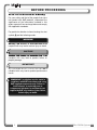
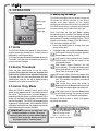
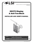
WIRELESS TECHNOLOGY & CRANE INSTRUMENTATION
DIVISIONS
GS320 Display
& Wind Speed Sensor
INSTALLER AND USER’S MANUAL
ww
w.l
oa
ds
ystte
ms
.co
m
Lo
Baw
tt
m/s
Sta
tus
mp
h
Ala
rm
Se
t
Lim
it
GS
320
! WARNING!
!
Win
dS
pee
d In
dic
ato
r
The GS320 system is designed as an operator aid and is in no way a
substitute for safe operating practice.
WARNING! Carefully read and understand this manual before proceeding.
GM320_ENG_rev20110516
www.loadsystems.com
BEFORE PROCEEDING
Read and understand the following:
For your safety and that of the people that come
into contact with LSI products, understand the
significance of the instructions included in this
guide, respect all laws and regulations and comply
with applicable standards.
Pay particular attention to items bearing the alert
symbol ! and the following words:
!
WARNING!
Warning: this denotes an instruction that if not
complied with may lead to serious injury or death.
!
CAUTION!
Caution: this denotes an instruction that if not
complied with may lead to product failure or
property damage.
!
IMPORTANT!
Important: this denotes an instruction that if not
complied with may lead to product performance
issues.
!
WARNING! Installation must be made in
compliance with LSI instructions and using
LSI supplied components only. Failure to
install all parts, or replacing parts or
components with parts or components not
supplied by LSI , may lead to system failure,
serious injury or death.
2
The GS320 System
TABLE OF CONTENTS
1. INTRODUCTION
1.1 OVERVIEW ........................................4
1.2 START-UP ..........................................4
1.3 RECOMMENDED OPERATING
CONDITIONS ....................................4
2. INSTALLATION
2.1 DISPLAY GS320 ................................5
2.1a Mounting Bracket ........................................5
2.1b Antenna Position ........................................6
2.1c Power Supply and Lockout Connection ......6
2.2 WIRELESS WIND SPEED SENSOR
GS020 ................................................7
3. OPERATION
3.1 UNITS ................................................8
3.2 ALARM THRESHOLD ......................8
3.3 LISTEN ONLY MODE ........................8
3.4 DISPLAY SETTINGS ........................8
5. CERTIFICATION NOTES
5.1 FCC AND IC – INSTRUCTIONS TO
THE USER ......................................11
5.2 CE ....................................................12
5.2a Declaration of conformity ..........................12
5.2b CE Safety..................................................12
6. LSI PRODUCT LIMITED
WARRANTY - 2009/02/16
6.1 LIMITED WARRANTY ....................13
6.2 WARRANTY SERVICES
PROCEDURES ................................13
6.3 EXCLUSION OF OTHER
WARRANTIES ................................13
6.4 EXCLUSION ....................................14
6.5 LIMITATION OF LIABILITY ............14
6.6 RECOMMENDED PRACTICES ......14
6.7 CHOICE OF LAW ............................14
6.7a Entire Agreement ......................................14
4. MAINTENANCE
4.1 REPLACING THE SENSOR
BATTERY ..........................................9
4.2 REPLACING THE SENSOR
ANTENNA........................................10
TABLE OF CONTENTS
OPERATION
3
1. INTRODUCTION
1.1 Overview
The wind speed indicator kit includes a GS320
display and a wind speed sensor. The GS320
creates a two-way radio network with the wind
speed sensor to bring live readings on screen. The
GS320 has a user adjustable maximum wind
speed limit and will generate an alarm when this
limit is reached. Furthermore, when in alarm
voltage is generated on the green wire; this can be
used to activate a remote siren, light or lockout
function.
1.2 Start-Up
On power up, the display will show two horizontal
lines and the green status light will flash.
Once a reliable radio communication network is
established, the display lights will remain lit without
flashing.
If the status light flashes continuously for more than
30 seconds the GS320 may not be correctly
programmed for the wind speed sensor. To
correctly program the GS320 for the wind speed
sensor follow the Wind speed ID number
procedure in the Operation section of this manual.
1.3 Recommended Operating
Conditions
Supply voltage:
9 to 30 volts
Current requirements:
maximum 1 amperes
Output wire voltage:
0 volts or supply voltage - 0.7 volts
Output wire current capability:
0.75 amperes
Operating temperature:
-40°C to +85°C (-40°F to 185°F)
4
The GS320 System
2. INSTALLATION
!
WARNING! Installation must be made in
compliance with LSI instructions and using
LSI supplied components only. Failure to
install all parts, or replacing parts or
components with parts or components not
supplied by LSI , may lead to system failure,
serious injury or death.
2.1 Display GS320
!
IMPORTANT! Do not crack or puncture
the membrane fascia. The GS320 display is
splash and rain proof. Waterproofing depends in
part on the integrity of the membrane.
IMPORTANT! Do not power wash the
display. The GS320 display is not designed to
withstand high-pressure washing devices that
can erode the membrane fascia seal or create
fissures in the membrane fascia. Power washing
the display voids warranty coverage.
reliable radio communication between wind
speed sensor and the GS320, the antenna
should not be in contact with metal and
should have a direct and clear line of sight
to the sensor antenna. The mounting bracket
requires a flat surface of at least 2.5 inches in
diameter on both sides and where the back of
the surface is accessible in order to tighten the
nuts.
2. Drill 1/4 inch boltholes through the mounting
surface with a 1/4 inch bit following either the
two, three, or the four holes configuration.
0.906
ø2.5 in. min.
flat surface
0.594
0.594
ø0.218
120° TYP
0.750
0.750
Figure: Display mounting bracket footprint. Not to scale.
Field replaceable
antenna
Part number: TA008
Rugged
aluminium
enclosure
Two way radio
system
ww
w.lo
ad
syst
em
s.co
m
Lo
Baw
tt
m/s
Sta
tus
mph
Ala
rm
Se
t
Lim
it
GS
320
Waterproof
design
Win
dS
pee
d In
dic
ato
r
Adjustable
Ram-Bracket
with dual ball joints.
Part number: LB002B
3. Install the display with bolts. Add washers and lock
nut behind the mounting surface and tighten
sufficiently (bolts, nuts and washers not included).
Note: If the nuts are on the outside of the cab,
caulk with silicone between the washers and the
cab to prevent water entry.
4. Loosen the wing nut of the bracket arm to adjust
display orientation to facilitate viewing by the
operator and then tighten it back up.
Figure: Display GS320
1.37
Wing
Nut
www.loadsystems.com
Low
Batt
m/s
mph
4.70
4
.70
70
Status
6.19
2.44
Alarm
Set
Limit
www.
loads
ystem
s.com
GS320 Wind Speed Indicator
8.83
3.70
Low
Batt
2.20
m/s
Figure: Display dimensions (inches). Not to scale.
2.1a Mounting Bracket
1. Determine the mounting location; the display
may be installed either inside or outside the
cab. It can be mounted on the dash, on a
sidewall, or on the ceiling of the cab. To ensure
INSTALLATION
mph
Stat
6.49
us
Alarm
Set
Lim
it
GS3
20
Win
d
d Sp
eed
Indic
ator
Cab mounting
surface
Figure: Install the display and adjust orientation
5
2.1b Antenna Position
For optimal performance the antenna should be
positioned on its side such that it is parallel to
the sensor antenna (but not pointing directly to or
directly away from it).
← To GS320
To valve coil if
normally open is
required
Bosch relay
1. Adjust the antenna position with the articulating base.
2. The antenna should have 5 inches of clear
space all around it.
3. The antenna should have an unobstructed line of
sight to all sensor antennas at all boom angles.
2.1c Power Supply and Lockout
Connection
1. Connect the blue wire (ground) to the negative
terminal of the battery or the panel connection;
alternatively bolt the blue wire to the body of the
machine with a 1/4 inch or 5/16 inch bolt. The
ground connection must be strong enough to
sustain 3 amperes.
Green wire - Lockout
n.c.
Red wire
n.o.
Blue
wire
co
Power Supply
or Battery
+12 V or +24 V
To valve coil if
normally closed
is required
Figure: Connection with green wire lockout and recommended
Bosch relay.
2. Connect the red wire to a fused accessory
source, rated at least 3 amperes, that supplies
+12 or +24 volts when the machine is in use.
The GS320 will automatically detect the voltage
level and adjust itself.
3. Lockout wire (if required): connect the green
wire to a Bosch relay coil terminal. Connect the
other coil terminal of the relay to the ground.
When in safe condition, the green wire will
energize at the battery positive level.
Current over 1 ampere on the green wire
triggers an auto re-settable fuse. Current flow
will resume several seconds after the short
circuit is eliminated.
Troubleshooting: if no voltage is present on the
green wire remove the load connected to it.
6
The GS320 System
2.2 Wireless Wind Speed
Sensor GS020
c. The wind cups must be fully exposed to
the wind and spin freely at all boom
angles.
Mounting rod
Figure: GS020 wireless wind speed sensor
1. Remove the mounting rod from the wind speed
sensor.
! IMPORTANT!
Do not weld in proximity to
LSI sensor/transmitters.
2. Determine the mounting rod position.
Figure: Wind clearance
d. There should be a clear and unobstructed
line of sight between the wind speed
sensor antenna and the cabin mounted
display unit.
a. Install the mounting rod on the same side
of the boom as the cabin mounted
display, perpendicular to the boom, and
at the highest point possible.
b. The wind speed sensor must pivot freely
on the mounting rod at all boom angles.
Figure: Radio line of sight - Crane top view
e. The transmitter antenna should not
contact any metal object.
Note: Angle iron can be used to extend the
mounting position to be clear of the boom top.
3. Weld or screw the mounting rod to the boom at
the selected position.
Figure: Swivel orientation
INSTALLATION
4. Re-position the wind speed sensor on the
mounting rod, add the washer and secure with
the cotter pin.
7
3. OPERATION
3.4 Display Settings
www.loadsystems.com
ww
ww
Low
Batt
m/s
Battery light
Units
mph
Status
Alarm
Alarm light
Status light
Set
Limit
GS320 Wind Speed Indicator
3.1 Units
This section describes how to manually change the
ID number the GS320 will listen to, and how to
change some other behavior of this display.
Changing the wind speed ID number is required only
if the wind speed sensor is changed and the display
must be manually set to listen to an other one.
Press and hold the Up and Down buttons
simultaneously for 5 seconds. The display will beep
and then indicate the currently programmed wind
speed sensor ID number, one digit at a time. The ID
number must contain 6 digits, if the ID number is
120, the three first digits are “000”.
1. Press Set Limit button to change from one
screen to the next.
The GS320 indicates wind speed in miles per hour
(mph) or metres per second (m/s). Current units are
indicated by a small green light.
2. To change a digit, use the Up and Down buttons.
To change units press and hold the Down button for
5 seconds. Verify the alarm threshold every time the
current units are changed.
“LA” means Listening Mode Active. Another
GS320 dislay must be the master of the
wind speed sensor.
3.2 Alarm Threshold
Press the Set Limit button to see the alarm
threshold. Every time the units are changed, the
limit must be verified and re-adjusted if required.
To change the limit, press and hold down the Set
Limit button, and use the Up or Down buttons
repeatedly to increase or lower the limit.
3.3 Listen Only Mode
When the GS320 is started it wakes up the wind
speed sensor programmed to it and takes control of
the sensor. This means that if a second display is
programmed for the sensor, it will take control of it; the
sensor will no longer acknowledge communication
from the first display. The GS320 can be programmed
to operate in “listening mode”. In this mode the GS320
will display information from the programmed sensor
without becoming the network controller.
! IMPORTANT!
A sensor can only have one
network controller at a time. To receive
communication from a sensor without taking
control of that sensor the display must first
be programmed in “listening mode”.
8
“Ld” means Listening De-activated (default).
Press Down to change to “LA”.
“OS” means Output Standard: fail safe
output (default). The output provides power
when wind speed is safe, below the limit.
Press Down to change to “OI”.
“OI” means Output Inverted: the output wire
is energized when wind speed is above the
limit. This could be use to power an external
siren or horn.
“SA” means Save. When this screen is
displayed, press the Down button to save the
ID number and above options and then exit.
“CA” means Cancel. Press the Down button
to exit without saving. The system will retain
the previously set ID number and options.
Example: if the ID number is 18820, it will appear
like this on the screen:
Set
Limit
ID number digits
Indicates the digit number
(first “1.”, second “2.”, etc.)
Figure: Example ID number 18820
The GS320 System
4. MAINTENANCE
4.1 Replacing the Sensor
Battery
!
!
IMPORTANT! Protect the interior of the
sensor from dirt and humidity at all times.
IMPORTANT! Both lithium or alkaline
batteries can be used, however lithium
battery will last about 2.5 times longer.
5. Install the new battery: insert the positive end and
then push in the direction of the positive pole.
Note: A 3.6 volt lithium “D” cell battery will provide
about two years of battery life, while an alkaline “D”
cell battery will provide less than one year of
battery life*.
New high quality “D”
cell battery: 3.6 V lithium,
5
or alkaline
1. Unscrew the two allen screws about a quarter
of an inch.
7
2. Insert a flat bladed screwdriver in the battery
cover notch to pry the box away from the
mounting plate. The silicone seal may cause
some resistance.
1
Hex key 5/32 in.
1/4 in.
Figure: Install the new battery
6. Apply a non-corrosive RTV silicone all around
the edge of the mounting plate to create a new
seal without bubbles or breaks.
2
RTV non-corrosive
silicone 6
Flat bladed
screwdriver
Figure: Remove the sensor box from the mounting plate
3. Remove the battery by hand.
4. Remove the remaining silicone from both the
box and the mounting plate.
Figure: Apply non-corrosive RTV silicone
7. Reposition the box over the mounting plate and
screw in the hex screws. Do not over-tighten.
* Actual battery life will vary greatly depending on
the application, the frequency of use, the age and
quality of the battery etc.
MAINTENANCE
9
4.2 Replacing the Sensor
Antenna
Heavily damaged antennas (ripped out, sheared off,
wire exposed and fraying etc.) should be replaced to
ensure effective communication between the sensor
and the cabin mounted display unit.
7. Slide the white nylon hex bolt to the middle of
the length of the new antenna.
8. Coat the exposed metal foot of the new antenna
with an electrical insulating compound by
carefully inserting it in the mouth of the
compound tube.
This procedure may be followed without removing
the sensor from the crane if it is safe to do so.
!
IMPORTANT! The interior of the sensor
must be protected from dust, grime and
water at all times.
Electrical insulating
compound
8
Figure: Coat the exposed metal foot of the antenna
1. Place the crane, boom, jib or ball hook such that
the sensor is safely accessible.
2. Clean dust, grime and water from the sensor.
3. Identify the short black whip antenna and the
white hex bolt securing it.
4. Inspect the antenna for signs of obvious
physical damage.
9. Hold the new antenna by the black plastic
sheathing and guide it through the hole in the
sensor box. Carefully seat the antenna in its
mating connector. When the antenna is
correctly seated, pulling on it will be met with
light resistance.
5. Carefully unscrew the white nylon hex bolt
completely and slide it up the antenna.
White nylon hex bolt
TA011 Antenna
Sensor box
7/16 in.
wrench
5
Antenna receptacle
Figure: Unscrew the white nylon hex
6. Grip the antenna by the base of the black
plastic sheathing and pull it straight out of the
hole in which it is seated. Place the old antenna
aside.
Figure: Install the new antenna
10. Carefully re-thread, screw-in and tighten the
white nylon hex bolt to secure the antenna in
place. Do not overtighten.
11. Reinstall the sensor if necessary.
12. Verify that the sensor functions properly.
6
Figure: Pull out the antenna
10
The GS320 System
5.2 CE
5.2a Declaration of conformity
5.2b CE Safety
!
!
WARNING! When captors are used, the
ambiant temperature should not be higher
than 84°C and the display should not be used
when the ambiant temperature is higher than
59°C, otherwise there can be a burn possibility.
! WARNING!
The protection will be impared if
the material and equipment are used in a
manner not specified by the manufacturer.
!
IMPORTANT! The IP of equipment
corresponds to 65.
WARNING! For the operator’s safety, take
only the ambiant temperature range into
consideration. The device should be used
within this range specified above.
12
The GS320 System
6. LSI PRODUCT LIMITED WARRANTY - 2009/02/16
6.1 Limited Warranty
LOAD SYSTEMS INTERNATIONAL INC. (hereafter
“LSI”)
LSI warrants its products (the “Products”), for a
period of twenty four (24) consecutive months after
delivery of such Products to the user (as evidenced
on a LSI document) (the “Warranty Period”), when
installed and used in accordance with specifications
described in LSI Installer and User’s Manual, as
amended from time to time , LSI technical materials
and any related writings published by LSI with
respect with such Products and any industry
standards, will be free from defects in materials and
workmanship. During the Warranty Period, LSI or its
designated service representative shall repair, or at
its option, replace any Product that is confirmed to be
defective by LSI,
LSI in its sole discretion, in accordance
with the Limited Warranty Services Procedures
described below.
6.2 Warranty Services
Procedures
In order to benefit of this-mentioned Limited Warranty
coverages and benefits, the purchaser must notify
LSI’s
LSI customer service or LSI’s
LSI authorized distributor
or representative originally responsible for the sale of
the Products within 10 days of the occurrence of a
suspected defect in materials or workmanship, prior
to the expiry of the Limited Warranty Period in order
to obtain a Return Authorization Number. A proof of
purchase of the Product, such as an invoice or a
receipt certifying the validity of the Warranty, must be
presented in order to obtain Limited Warranty
coverage. In any event, even if a Return Authorization
Number is provided to purchaser, LSI reserves the
right to inspect the damaged Product or part before
the final decision of repairing or replacing the
defective Product or part.
The Product or part shall be returned to LSI or its
designated service representative, accompanied by
the Return Authorization Number with prepaid
shipping charges. The purchaser must insure the
shipment or accept the risk of loss or damage during
the shipment. Purchaser shall also pay any tariff or
duty applicable to the return of defective part or
Product. LSI will, at its option, repair or replace the
Product or part returned to LSI or to its designated
service representative. LSI owns all parts or Products
replaced, repaired or removed from a repaired
Product. If LSI repairs a Product, the Product
LSI PRODUCT WARRANTY
Warranty coverage Period is not extended and the
Limited Warranty shall expire as if uninterrupted upon
the occurrence of the 24th month from shipping from
LSI.
LSI If LSI replaces a Product, the replaced Product
is warranted for the remainder of the original term or
sixty consecutive (60) days, whichever is longer.
LSI reserves the right to require from you the user or
owner of the Products, prior to determining if the Limited
Warranty coverage is applicable, that LSI receive the
data logging equipment used with the Products and that
LSI be authorized to retrieve all information from such
data logging equipment in order to, among others,
ensure that the written instructions and applicable
standards, including safety margins, were respected
and not exceeded during Product use. Failure by you
the owner or user of the Product to supply such
information shall be deemed a material default of the
terms and conditions of this Limited Warranty and shall
be irrevocably construed as evidence that the Product
was misused or abused. Consequently LSI shall
irrevocably be relieved of any obligations to
compensate you the user or owner of the Product for
any and all damages resulting from Product failures
when data logging equipment, and access to its
content, cannot be freely and readily provided,
unhampered, to LSI.
LSI
LSI will pay ground freight transportation costs
of replacement or repaired parts or Products to
the destination in Canada and the continental
United States of America (the “Territory”). LSI will
not pay any transportation costs of replacement
or repaired parts to destination outside of the
Territory. Shipping and handling costs to
locations outside the Territory shall be the
responsibility and borne by Purchaser or Owner
of the Product prior to any shipment by LSI.
LSI
(Contact LSI to get a Return Authorization
Number and the address to ship parts).
6.3 Exclusion of Other
Warranties
THE ABOVE WARRANTY IS THE SOLE WARRANTY
APPLICABLE AND THERE ARE NO EXPRESS,
LEGAL OR IMPLIED WARRANTIES OR CONDITIONS
IN RELATION TO ANY PRODUCTS INCLUDING ANY
IMPLIED WARRANTY OR CONDITION OF
MERCHANTABILITY, NON-INFRINGEMENT OR
FITNESS FOR A PARTICULAR PURPOSE AND
THOSE OTHERWISE ARISING BY STATUTE OR
OTHERWISE IN LAW OR FROM A COURSE OF
13
DEALING OR USAGE OF TRADE, WHICH ARE
EXPRESSLY DISCLAIMED. NO ORAL OR WRITTEN
INFORMATION OR ADVICE GIVEN BY LSI OR ITS
EMPLOYEES OR REPRESENTATIVES SHALL
CREATE A WARRANTY OR CONDITION OR IN ANY
WAY INCREASE THE SCOPE OF LSI’S
LSI OBLIGATION.
LSI DOES NOT WARRANT THAT THE BUSINESS
RESULTS OBTAINED FROM THE USE OF THE
PRODUCTS WILL BE APPROPRIATE OR ADEQUATE
FOR THE PURCHASER.
6.4 Exclusion
This Limited Warranty does not cover and shall not
apply to:
•
Any Product that is misused or abused, including
being altered, modified or repaired not in
accordance to LSI written instructions or
authorizations and any use not in compliance with
LSI’s
LSI instructions and/or industry standards and
practices;
•
Any incidental costs or expense, such as shipping
charges to LSI or an designated service
representative as well as the technician out-ofpocket expenses including traveling, lodging and
meal expenses, if any;
•
The damages caused during the transport or the
moving of the Products;
•
Damages caused by accidents, abuse, misuse, a
force majeure (described as events outside a
LSI’s
LSI or any Product user’s control, including war,
riot, strikes, embargoes) or external cause;
•
Any cost, damage or expenses for field labor or
any other expenses related to or arising from the
replacement of defective parts.
•
Products used for pile-driving, wire rope activated
clamshell or dragline applications. If purchaser
uses the Products for pile-driving, wire rope
activated clamshell or dragline application, the
limited warranty will be deemed to have been
violated for abuse.
•
Any costs associated with providing LSI with data
logging equipment.
6.5 Limitation of Liability
To the maximum extent permitted by applicable law,
in no event will LSI be liable to the purchaser or any
third party for any indirect, special, consequential,
incidental or exemplary damages whatsoever,
including but not limited to loss or revenue or profit,
lost or damaged data, business interruption or any
other pecuniary loss whether based in contract, tort or
14
other causes of action, even if LSI has been advised
of the possibility of such damages. In any event, the
total liability of LSI arising from any cause of action or
claim whatsoever, whether (1) in contract, (2) in tort
(including negligence, whether sole, joint,
contributory, concurrent or otherwise, but not
including intentional, reckless or wanton tort), (3)
under strict liability, (4) under any environmental or
antipollution law or regulation, (5) connected with any
toxic or hazardous substance or constituent, (6)
arising out of any representation or instruction, or
under any warranty, (7) or otherwise, arising out of,
connected with, or resulting from the design,
manufacture, sale, resale, delivery, repair,
replacement or use of Products or the furnishing of
any service shall in no event exceed the price
allocable to and paid to LSI for the individual unit of
Products or service or part thereof which gives rise to
the cause of action or claim.
SOME STATES OR JURISDICTIONS DO NOT
ALLOW THE LIMITATION OR EXCLUSION OF
LIABILITY FOR INCIDENTAL OR CONSEQUENTIAL
DAMAGES, SO THE ABOVE LIMITATION OR
EXCLUSION MAY NOT APPLY TO YOU.
6.6 Recommended Practices
LSI recommends careful consideration of the
following factors when specifying and installing the
Products. Before installing a Product, the Installation,
Operation, and Maintenance instructions provided
with the unit must be read and understood and
complied with.
6.7 Choice of law
This Limited Warranty shall be governed by and
construed in accordance with the laws of : 1. For
Products sold in Canada: the Province of Quebec or,
For Products sold in the USA: the State of Florida,
without giving effect to principles of conflicts of law.
You agree that the exclusive venue for any disputes
arising under this Agreement shall be the state and
federal courts located in Orlando, Florida.
6.7a Entire Agreement
This document contains the entire agreement of the
parties regarding the subject matter of the Product
and supersedes all previous communications,
representations, understandings and agreements,
either oral or written, between you and LSI.
LSI
The GS320 System
NOTES
NOTES
15
LSI Contact Information
Technical Support:
LSI Technical Support is available 24 hours a day, 7 days a week from our
Houston and Dubai locations.
Please direct all technical support questions to either of these locations or
contact us via email:
[email protected]
North America
Middle East & Africa
Toll Free Phone: (888) 819 4355
Toll Free Fax: (888) 238 4099
International: +1 (281) 664 1330
USA Corporate Office:
9633 Zaka Road
Houston, TX 77064
Direct Phone: 281.664.1330
Direct Fax: 281.664.1390
Email: [email protected]
Phone: +971 6 557 8314
Fax: +971 6 557 8315
Canadian Corporate Office:
4495 Blvd. Hamel, Suite 110
Quebec QC G1P 2J7
Direct Phone: (418) 650 2330
Direct Fax: (418) 650 3340
Email: [email protected]
Dubai Corporate Office:
Q3-171 SAIF Zone. PO Box 7976
Sharjah UAE
Phone: +971 6 557 8314
Fax: +971 6 557 8315
Email: [email protected]
© 2011, Load Systems International Inc.
GM320_ENG_rev20110516
www.loadsystems.com