1
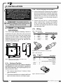
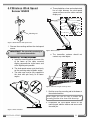
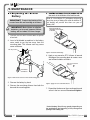
WIRELESS TECHNOLOGY & CRANE INSTRUMENTATION
DIVISIONS
GS221-02/05/07 System
& GS Series Sensors
INSTALLER AND USER’S MANUAL
! WARNING!
!
The GS221 system is designed as an operator aid and is in no way a
substitute for safe operating practice.
WARNING! Carefully read and understand this manual before proceeding.
GM221-02-05-07_ENG_rev20110612
www.loadsystems.com
BEFORE PROCEEDING
Read and understand the following:
For your safety and that of the people that come
into contact with LSI products, understand the
significance of the instructions included in this
guide, respect all laws and regulations and comply
with applicable standards.
Pay particular attention to items bearing the alert
symbol ! and the following words:
WARNING!
!
Warning: this denotes an instruction that if not
complied with may lead to serious injury or death.
CAUTION!
!
Caution: this denotes an instruction that if not
complied with may lead to product failure or
property damage.
IMPORTANT!
!
Important: this denotes an instruction that if not
complied with may lead to product performance
issues.
!
WARNING! Installation must be made in
compliance with LSI instructions and using
LSI supplied components only. Failure to
install all parts, or replacing parts or
components with parts or components not
supplied by LSI , may lead to system failure,
serious injury or death.
2
The GS221 System
TABLE OF CONTENTS
1. INTRODUCTION
1.1 OVERVIEW ........................................4
1.2 START-UP..........................................4
2. OPERATION
2.1 NORMAL OPERATION ....................4
3. CONFIGURATION
3.1 PC INSTALLATION ..........................5
3.1a System Requirements ................................5
3.1b LSI WM Configurator and USB Driver
Installation ..................................................5
3.1c LSI Gateway Connection ............................5
3.2 APPLICATION OVERVIEW ..............6
3.2a
3.2b
3.2c
3.2d
3.2e
3.2f
Settings ......................................................6
Communication Port ..................................6
Configuration ..............................................6
Firmware Update ........................................6
Datalogger Mode ........................................6
Sensor Settings ..........................................7
3.3 SENSOR LIST ..................................7
5. MAINTENANCE
5.1 REPLACING THE SENSOR
BATTERY ........................................12
5.2 REPLACING THE SENSOR
ANTENNA........................................13
6. CERTIFICATION NOTES
6.1 FCC AND IC – INSTRUCTIONS TO
THE USER ......................................14
6.2 CE ....................................................15
6.2a Declaration of conformity ..........................15
6.2b CE Safety..................................................15
7. LSI PRODUCT LIMITED
WARRANTY - 2009/02/16
7.1 LIMITED WARRANTY ....................16
7.2 WARRANTY SERVICES
PROCEDURES ................................16
7.3 EXCLUSION OF OTHER
WARRANTIES ................................16
3.4 FIRMWARE UPDATE
(LSI GATEWAY ONLY) ......................7
7.4 EXCLUSION ....................................17
3.5 PACKET FORMAT ............................8
7.6 RECOMMENDED PRACTICES ......17
3.6 CHANGING SENSORS ....................9
7.7 CHOICE OF LAW ............................17
3.6a Automatic sensor settings ..........................9
3.6b Manual sensor setting ................................9
7.7a Entire Agreement ......................................17
7.5 LIMITATION OF LIABILITY ............17
4. INSTALLATION
4.1 GS221 LSI GATEWAY
INSTALLATION ..............................10
4.1a Antenna Position ......................................10
4.1b Power Supply Connection ........................10
4.1c Wiring ........................................................10
4.2 WIRELESS WIND SPEED
SENSOR GS020 ..............................11
TABLE OF CONTENTS
3
1. INTRODUCTION
1.1 Overview
1.2 Start-Up
The GS221 LSI Wireless Gateway acts as a base
station for GS series wireless sensors. Not limited
to crane applications the LSI Gateway can be
used in a wide range of industrial process
monitoring situations. The LSI Gateway doesn't
have an integrated display; it provides a bridge
from GS wireless sensors to an existing CAN bus
automotive or industrial automation network. The
system is primarily configured via a USB cable
using the PC software tool LSI WM Configurator.
The LSI Gateway has been pre-configured for the
system with which it shipped. It starts up with its
green light flashing as it wakes up the system
sensors and creates a radio communication link
with each. Once a reliable communication network
is established, the green light stops flashing. This
process may take up to 60 seconds. Thereafter the
green light flashes only when the LSI Gateway
communicates with sensors.
! WARNING!
The GS221 system is designed
as an operator aid and is in no way a
substitute for safe operating practice.
2. OPERATION
2.1 Normal operation
Radio communication between sensors and the
LSI Wireless Gateway is made in packets. Radio
packets include both the source and destination ID
numbers. This allows the LSI Gateway to send
acknowledgements back to the transmitter.
On start-up the LSI Gateway sends a radio packet
to each of the system sensors. This communication
wakes the sensor and identifies the LSI Gateway
as the network controller. The sensor then sends
future communications to the LSI Gateway.
4
Sensors transmit once every 60 seconds and
whenever their measurement changes by more
than a default threshold. Example: A wind speed
sensor transmits when wind speed varies by 2 mph
or more.
The LSI Gateway sends a packet on the CAN bus
network every time a sensor communication is
received.
The GS221 System
3. CONFIGURATION
Configuration of the GS221 LSI Wireless
Gateway requires access to a PC with a USB port;
initial configuration may be easier prior to physical
installation of the LSI Gateway. Refer to the
Installation section as required.
5. When the installation wizard has finished
installing the software, click Finish to close the
wizard.
When the installation is completed, the Device
Manager will appear as shown below;
3.1 PC Installation
3.1a System Requirements
Windows 2000, XP, Vista (32/64bit) or Windows 7
(32/64bit).
3.1b LSI WM Configurator and USB
Driver Installation
Before starting installation, make sure that no
LSI Gateway is not connected to the computer.
1. Download
the
installation
file
www.loadsystems.com/wmconfigurator.
Figure: Device Manager, Windows Vista / Windows 7
from
2. Install the file and follow the steps from the
installation wizard.
When transfering the files, the installation
wizard will automaticly execute the USB driver
installation; a Windows warning will recommend
to stop the installation, ignore this warning and
select Continue Anyway (Windows XP) or
Install this driver anyway (Windows Vista,
Windows 7).
3.1c LSI Gateway Connection
Windows Vista / Windows 7:
1. Connect the LSI Gateway to the computer; the
device will automatically be installed.
Windows XP:
1. Connect the LSI Gateway to the computer;
Found New Hardware Wizard will appear.
Figure: Device Manager, Windows XP
! WARNING!
The system must be installed
in compliance with LSI instructions and
using LSI supplied components only. Failure
to install all parts, or replacing parts or
components with parts or components not
supplied by LSI , may lead to system failure,
serious injury or death.
2. If Windows asks to connect to Windows Update
to search for software, select No, not this time
and then click Next.
3. Select Install the software automatically,
then click Next to continue.
4. A Windows warning indicating that the driver
has not been tested will recommend to stop the
installation, ignore this warning and select
Continue Anyway.
CONFIGURATION
--SECTION--
5
3.2 Application overview
Access the menus from the treeview (in the upperleft) by clicking on it. The appropriated details will
be displayed in the right section of the application.
Figure: Sensor List.
LSI Gateway Internal Ports:
The LSI Gateway internal communication ports
behavior can be configured in the LSI Gateway
Internal Ports section.
Figure: Application overview.
3.2a
•
Step 1: Select the LSI Gateway internal port
to be configured.
•
Step 2: Set the data logging options of the
selected port.
Settings
The data from the datalogger mode can be saved
on the computer disk.
The data logging options set are
compatible with the Datalogger Mode
from the left menu.
1. Define the time interval and location folder of
the logs.
Data Filter: Defines the information sent to the
internal communication port;
All sensors: Surrounding
including the system sensors.
2. Press Apply to save changes or Cancel to
reload existing setting.
sensors,
System Sensors Only: Sensors
configured in the LSI Gateway.
•
Step 3: Set advanced port settings.
Figure: Settings
3.2b Communication Port
This section displays the communication port in use,
the port type and status. The Open status indicates
that the communication port is in use and that the
LSI Gateway is communicating information.
Figure: LSI Gateway Internal Ports.
3.2c Configuration
3.2d Firmware Update
Sensor List:
This section displays current LSI Gateway firmware
information and is used to update the firmware.
Refer to section 3.4 Firmware Update.
All sensors in the GS221 system are defined in the
Configuration menu and are also displayed under
Sensor Settings in the treeview section. Refer to
section 3.3 Sensor List to add, remove or modify
sensor information.
6
3.2e Datalogger Mode
In this mode, live information sent by the wireless
sensors is displayed. The data can be logged to files;
see the 3.2a Settings section to configure this feature.
The GS221 System
3.2f
Sensor Settings
When a sensor is selected under Sensor Settings,
the following information is communicated to the LSI
Gateway;
•
Base Station ID: The radio id number of the LSI
Gateway that has the sensor programmed in its
sensor list.
•
Heart Beat: When no change is detected in
sensor value, the sensor status will be
communicated to the GS221 in the interval
indicated (in seconds).
•
Communication timeout before sleep mode:
When the base station stops communicating
information to the sensors, the sensors become
innactive (sleep mode). The value indicated is
the time (in seconds) before the sensors switch
to the sleep mode.
•
Calibration Offset: Sensor calibration.
•
Calibration Scale: Sensor calibration.
•
Tx Sensivity: The minimum change in sensor
value required to trigger communication.
4. Reload from LSI Gateway: Reload data from
the LSI Gateway and display data without
saving any changes (the unsaved data in the
LSI Gateway will be replaced).
5. Save to LSI Gateway: Save changes in the
LSI Gateway memory. Save to LSI Gateway
is automaticly followed by Update sensor
status.
3.4 Firmware Update ( LSI
Gateway only)
1. Select Firmware Update in the treeview
section.
2. In the right section, click on Browse to select
the update file (extension .220) and then click
Update Firmware Now.
! IMPORTANT!
A firmware update will reset
the LSI Gateway to the factory default
configuration.
Figure: Firmware update.
Figure: Sensor standard setup.
3.3 Sensor List
1. In the Configuration menu, select Sensor List.
2. Adding sensors: To add sensors to the sensor
list;
Select a line and click on Configure selected
line or double-click on the line.
Enter the sensor ID and the sensor type .
3. Removing sensors: To remove any sensor
from the list;
Select the sensor line to remove and click on
Remove selected sensor.
CONFIGURATION
--SECTION--
7
3.5 Packet Format
Temperature
Battery level
Wind speed
CAN bus
Destination ID
Nb Bytes
Type of sensor
6 = wind speed
Wind speed ID
number
Figure: CAN Bus packet format: example of a CAN Bus log window
Wind speed shown at 0x0F, which is 15 mph.
Battery level is: 0x64, decimal 100%
Temperature: 0x15, which converts into 21C.
Wind speed sensor ID number: 0x43Fc: 17404
CAN Bus packet format
Destination ID: . . . . . . . . . . . . . . . . . . . . $0405
Bit rate: . . . . . . . . . . . . . . . . . . . . . . 250kBits/s
Number of bytes. . . . . . . . . . . . . . . . . . . . . . . 6
Table 2: packet format
Byte
0
Description
LSI Sensor type
Number
Load cell, load pins, etc… . . . . . . . . . . . . . . . 1
Angle sensor . . . . . . . . . . . . . . . . . . . . . . . . . 2
Boom Length from cable reel. . . . . . . . . . . . . 3
Anti-two-block switch . . . . . . . . . . . . . . . . . . . 5
Wind speed . . . . . . . . . . . . . . . . . . . . . . . . . . 6
Rope Payout from line rider . . . . . . . . . . . . . . 8
Rope Speed from line rider . . . . . . . . . . . . . . 9
Heel angle sensor . . . . . . . . . . . . . . . . . . . . 10
List angle sensor . . . . . . . . . . . . . . . . . . . . . 11
Slew sensor (swing angle) . . . . . . . . . . . . . . 12
Wind Gust
(maximum wind in last 5 to 10 minutes). . . . 13
Data Range
Sensor type
Wind speed always
(see Table: Radio sensor types)
equal to 6
1
Wind speed sensor
ID number
MSB
2
Wind speed sensor
ID number
LSB
3
Wind speed value in mph
Unsigned byte,
between 0 and 200
4
Remaining battery life,
in percentage
Unsigned byte,
between 0 and 100
5
Table: Radio sensor types available
Sensor temperature in degrees Signed byte, between Celcius, -40C to +85C
40C & +85C
8
The GS221 System
3.6 Changing sensors
If a sensor needs to be changed, the LSI Gateway
must learn to recognize the replacement sensor.
Two mechanisms are available to change an ID in
the sensor list of the LSI Gateway.
1) Automatic ID change
2) Manual ID change
3.6a Automatic sensor settings
LSI will supply a replacement sensor programmed
to replace the original one. When the replacement
sensor is detected by the LSI Gateway it causes
the LSI Gateway to automatically update the
sensor list, replacing the ID of the old sensor with
that of the new; the process may take up to two
minutes to complete.
Note: The ID number included in the CAN bus
packet will change to reflect the different radio ID of
the new sensor.
3.6b Manual sensor setting
See Configuration 3.1 to 3.4.
CONFIGURATION
--SECTION--
9
4. INSTALLATION
!
!
WARNING! Installation must be made in
compliance with LSI instructions and using
LSI supplied components only. Failure to
install all parts, or replacing parts or
components with parts or components not
supplied by LSI , may lead to system failure,
serious injury or death.
IMPORTANT! Do not power wash the
GS221 LSI Gateway. Power washing the LSI
Gateway voids warranty coverage.
4.1 GS221 LSI Gateway
Installation
The GS221 LSI Wireless Gateway should be
installed on the same side of the cab as the wind
speed sensor with a direct clear line of sight to the
sensor at all boom angles. Avoid hiding the LSI
Gateway behind a metal structure if at all possible.
Optimizing position to improve the radio link will
increase sensor battery life.
5.85
4.72
4.1b Power Supply Connection
1. Connect the blue wire (ground) to the negative
terminal of the battery or the panel connection;
alternatively bolt the blue wire to the body of the
machine with a 1/4 inch or 5/16 inch bolt. The
ground connection must be strong enough to
sustain 1 ampere.
2. Connect the red wire to a fused accessory
source, rated at least 1 ampere, that supplies
+12 or +24 volts when the machine is in use.
The GS221 will automatically detect the voltage
level and adjust itself.
4.1c Wiring
Table:
Wire description
Wire
1
2
3
4
5
Description
M12 Connector wire color
. . . .Shield . . . . . . . . . .Brown
. . . .Power . . . . . . . . .White
. . . .Gnd . . . . . . . . . . .Blue
. . . .CAN_H . . . . . . . .Black
. . . .CAN_L . . . . . . . . .Gray
5
4
1
3
2
5.44
2.33
5.57
4.73
Figure: GS221-05 and GS221-07 connector pins
Table:
Wire description
Wire
Color
Figure: GS221 LSI Gateway dimensions. Not to scale.
Dimensions are in inches.
4.1a Antenna Position
Connector
Pin
Description
Red . . . . . . . .B . . . . . .Power supply, 10 to 30 volts
Black . . . . . . .C . . . . . . . . . . . . . . . . . . . . . . .Ground
Blue . . . . . . .G . . . . . . . . . . . . . . .CAN bus ground
. . . . . . . . . . . . . . . .(not required on most CAN bus)
Green . . . . . .E . . . . . . . . . . . . . . . . . . . . . . .CAN-H
White . . . . . . .F . . . . . . . . . . . . . . . . . . . . . . .CAN-L
For optimal performance the antenna should be
positioned on its side such that it is parallel to
the sensor antennas (but not pointing directly to or
directly away from them).
1. The antenna should have 5 inches of clear
space all around it.
2. The antenna should have an unobstructed line of
sight to all sensor antennas at all boom angles.
10
Figure: GS221-02 connector pin
The GS221 System
4.2 Wireless Wind Speed
Sensor GS020
d. There should be a clear and unobstructed
line of sight between the wind speed
sensor antenna and the cabin mounted
display unit.
Mounting rod
Figure: GS020 wireless wind speed sensor
1. Remove the mounting rod from the wind speed
sensor.
! IMPORTANT!
Do not weld in proximity to
LSI sensor/transmitters.
2. Determine the mounting rod position.
Figure: Wind clearance
e. The transmitter antenna should not
contact any metal object.
a. Install the mounting rod on the same side
of the boom as the cabin mounted
display, perpendicular to the boom, and
at the highest point possible.
b. The wind speed sensor must pivot freely
on the mounting rod at all boom angles.
c. The wind cups must be fully exposed to
the wind and spin freely at all boom
angles.
Figure: Radio line of sight - Crane top view
3. Weld or screw the mounting rod to the boom at
the selected position.
Note: Angle iron can be used to extend the
mounting position to be clear of the boom top.
4. Re-position the wind speed sensor on the
mounting rod, add the washer and secure with
the cotter pin.
Figure: Swivel orientation
INSTALLATION
--SECTION--
11
5. MAINTENANCE
5.1 Replacing the Sensor
Battery
IMPORTANT! Protect the interior of the
sensor from dirt and humidity at all times.
!
IMPORTANT! Both lithium or alkaline
batteries can be used, however lithium
battery will last about 2.5 times longer.
5. Install the new battery: insert the positive end and
then push in the direction of the positive pole.
Note: A 3.6 volt lithium “D” cell battery will provide
about two years of battery life, while an alkaline “D”
cell battery will provide less than one year of
battery life*.
New high quality “D”
cell battery: 3.6 V lithium,
6
or alkaline
1. Unscrew the two allen screws about a quarter
of an inch.
7
2. Insert a flat bladed screwdriver in the battery
cover notch to pry the box away from the
mounting plate. The silicone seal may cause
some resistance.
1
Hex key 5/32 in.
1/4 in.
Figure: Install the new battery
6. Apply a non-corrosive RTV silicone all around
the edge of the mounting plate to create a new
seal without bubbles or breaks.
2
RTV non-corrosive
silicone 8
Flat bladed
screwdriver
Figure: Remove the sensor box from the mounting plate
3. Remove the battery by hand.
4. Remove the remaining silicone from both the
box and the mounting plate.
Figure: Apply non-corrosive RTV silicone
7. Reposition the box over the mounting plate and
screw in the hex screws. Do not over-tighten.
* Actual battery life will vary greatly depending on
the application, the frequency of use, the age and
quality of the battery etc.
12
The GS221 System
5.2 Replacing the Sensor
Antenna
Heavily damaged antennas (ripped out, sheared off,
wire exposed and fraying etc.) should be replaced to
ensure effective communication between the sensor
and the cabin mounted display unit.
7. Slide the white nylon hex bolt to the middle of
the length of the new antenna.
8. Coat the exposed metal foot of the new antenna
with an electrical insulating compound by
carefully inserting it in the mouth of the
compound tube.
This procedure may be followed without removing
the sensor from the crane if it is safe to do so.
!
IMPORTANT! The interior of the sensor
must be protected from dust, grime and
water at all times.
Electrical insulating
compound
8
Figure: Coat the exposed metal foot of the antenna
1. Place the crane, boom, jib or ball hook such that
the sensor is safely accessible.
2. Clean dust, grime and water from the sensor.
3. Identify the short black whip antenna and the
white hex bolt securing it.
4. Inspect the antenna for signs of obvious
physical damage.
9. Hold the new antenna by the black plastic
sheathing and guide it through the hole in the
sensor box. Carefully seat the antenna in its
mating connector. When the antenna is
correctly seated, pulling on it will be met with
light resistance.
5. Carefully unscrew the white nylon hex bolt
completely and slide it up the antenna.
White nylon hex bolt
TA011 Antenna
Sensor box
7/16 in.
wrench
5
Antenna receptacle
Figure: Unscrew the white nylon hex
6. Grip the antenna by the base of the black
plastic sheathing and pull it straight out of the
hole in which it is seated. Place the old antenna
aside.
Figure: Install the new antenna
10. Carefully re-thread, screw-in and tighten the
white nylon hex bolt to secure the antenna in
place. Do not overtighten.
11. Reinstall the sensor if necessary.
12. Verify that the sensor functions properly.
6
Figure: Pull out the antenna
MAINTENANCE
--SECTION--
13
6. CERTIFICATION NOTES
6.1 FCC and IC – Instructions
to the User
This equipment has been tested and found to comply
with the limits for a class B digital device, pursuant to
part 15 of the FCC Rules. These limits are designed
to provide reasonable protection against harmful
interference in a residential installation. This
equipment generates, uses, and can radiate radio
frequency energy and if not installed and used in
accordance with the instructions, may cause harmful
interference to radio communications. However,
there is no guarantee that interference will not occur
in a particular installation. If this equipment does
cause harmful interference to radio or television
reception, which can be determined by turning the
equipment off and on, the user is encouraged to try
to correct the interference by one or more of the
following measures:
•
Reorient or relocate the receiving antenna.
•
Increase the separation between the equipment
and receiver.
•
Connect the equipment into an outlet on a
circuit different from that to which the receiver is
connected.
•
Consult the dealer or an experienced radio/TV
technician for help.
In order to maintain compliance with FCC
regulations, shielded cables must be used with this
equipment. Operation with non-approved equipment
or unshielded cables is likely to result in interference
to radio and TV reception.
! IMPORTANT!
Changes or modifications to
this equipment not expressly approved by the
party responsible for compliance could void
the user’s authority to operate the equipment.
FCC ID: QVBGS200
IC: 7076A-ICGS200
RF Exposure Warning:
This product complies with FCC/IC radiation
exposure limits set forth for an uncontrolled
environment. To comply with RF exposure
requirements, the unit must be installed and
operated with 20 cm (8 in.) or more between the
product and your body. This product may not be
collocated or operated in conjunction with any
other antenna or transmitter.
14
This device has been designed to operate with
the antennas listed below, and having a
maximum gain of 3.0 dB. Antennas not included
in this list or having a gain greater than 3.0 dB
are strictly prohibited for use with this device.
The required antenna impedance is 50 ohms.
To reduce potential radio interference to other
users, the antenna type and its gain should be
so chosen that the equivalent isotropically
radiated power (e.i.r.p.) is not more than that
permitted for successful communication.
Antenna List
LSI P/N:
Description:
MFG
TA011
1/4 wave monopole
Load Systems International
FCC ID: QVBGS000 IC: 7076A-ICGS000
FCC ID: QVBGS001 IC: 7076A-ICGS001
FCC ID: QVBGS050 IC: 7076A-ICGS050
FCC ID: QVBGS075 IC: 7076A-ICGS075
RF Exposure Warning:
This product complies with FCC/IC radiation
exposure limits set forth for an uncontrolled
environment. To comply with RF exposure
requirements, the unit must be installed and
operated with 20 cm (8 in.) or more between the
product and your body. This product may not be
collocated or operated in conjunction with any
other antenna or transmitter.
This device has been designed to operate with
the antennas listed below, and having a
maximum gain of 3.0 dB. Antennas not included
in this list or having a gain greater than 3.0 dB
are strictly prohibited for use with this device.
The required antenna impedance is 50 ohms.
To reduce potential radio interference to other
users, the antenna type and its gain should be
so chosen that the equivalent isotropically
radiated power (e.i.r.p.) is not more than that
permitted for successful communication.
Antenna List
LSI P/N:
Description:
MFG
TA011
1/4 wave monopole
Load Systems International
The GS221 System
6.2 CE
6.2a Declaration of conformity
6.2b CE Safety
!
!
WARNING! When captors are used, the
ambiant temperature should not be higher
than 84°C and the display should not be used
when the ambiant temperature is higher than
59°C, otherwise there can be a burn possibility.
! WARNING!
The protection will be impared if
the material and equipment are used in a
manner not specified by the manufacturer.
!
IMPORTANT! The IP of equipment
corresponds to 65.
WARNING! For the operator’s safety, take
only the ambiant temperature range into
consideration. The device should be used
within this range specified above.
CERTIFICATION NOTES
--SECTION--
15
7. LSI PRODUCT LIMITED WARRANTY - 2009/02/16
7.1 Limited Warranty
LOAD SYSTEMS INTERNATIONAL INC. (hereafter
“LSI”)
LSI warrants its products (the “Products”), for a
period of twenty four (24) consecutive months after
delivery of such Products to the user (as evidenced
on a LSI document) (the “Warranty Period”), when
installed and used in accordance with specifications
described in LSI Installer and User’s Manual, as
amended from time to time , LSI technical materials
and any related writings published by LSI with
respect with such Products and any industry
standards, will be free from defects in materials and
workmanship. During the Warranty Period, LSI or its
designated service representative shall repair, or at
its option, replace any Product that is confirmed to be
defective by LSI,
LSI in its sole discretion, in accordance
with the Limited Warranty Services Procedures
described below.
7.2 Warranty Services
Procedures
In order to benefit of this-mentioned Limited Warranty
coverages and benefits, the purchaser must notify
LSI’s
LSI customer service or LSI’s
LSI authorized distributor
or representative originally responsible for the sale of
the Products within 10 days of the occurrence of a
suspected defect in materials or workmanship, prior
to the expiry of the Limited Warranty Period in order
to obtain a Return Authorization Number. A proof of
purchase of the Product, such as an invoice or a
receipt certifying the validity of the Warranty, must be
presented in order to obtain Limited Warranty
coverage. In any event, even if a Return Authorization
Number is provided to purchaser, LSI reserves the
right to inspect the damaged Product or part before
the final decision of repairing or replacing the
defective Product or part.
The Product or part shall be returned to LSI or its
designated service representative, accompanied by
the Return Authorization Number with prepaid
shipping charges. The purchaser must insure the
shipment or accept the risk of loss or damage during
the shipment. Purchaser shall also pay any tariff or
duty applicable to the return of defective part or
Product. LSI will, at its option, repair or replace the
Product or part returned to LSI or to its designated
service representative. LSI owns all parts or Products
replaced, repaired or removed from a repaired
Product. If LSI repairs a Product, the Product
16
Warranty coverage Period is not extended and the
Limited Warranty shall expire as if uninterrupted upon
the occurrence of the 24th month from shipping from
LSI.
LSI If LSI replaces a Product, the replaced Product
is warranted for the remainder of the original term or
sixty consecutive (60) days, whichever is longer.
LSI reserves the right to require from you the user or
owner of the Products, prior to determining if the Limited
Warranty coverage is applicable, that LSI receive the
data logging equipment used with the Products and that
LSI be authorized to retrieve all information from such
data logging equipment in order to, among others,
ensure that the written instructions and applicable
standards, including safety margins, were respected
and not exceeded during Product use. Failure by you
the owner or user of the Product to supply such
information shall be deemed a material default of the
terms and conditions of this Limited Warranty and shall
be irrevocably construed as evidence that the Product
was misused or abused. Consequently LSI shall
irrevocably be relieved of any obligations to
compensate you the user or owner of the Product for
any and all damages resulting from Product failures
when data logging equipment, and access to its
content, cannot be freely and readily provided,
unhampered, to LSI.
LSI
LSI will pay ground freight transportation costs
of replacement or repaired parts or Products to
the destination in Canada and the continental
United States of America (the “Territory”). LSI will
not pay any transportation costs of replacement
or repaired parts to destination outside of the
Territory. Shipping and handling costs to
locations outside the Territory shall be the
responsibility and borne by Purchaser or Owner
of the Product prior to any shipment by LSI.
LSI
(Contact LSI to get a Return Authorization
Number and the address to ship parts).
7.3 Exclusion of Other
Warranties
THE ABOVE WARRANTY IS THE SOLE WARRANTY
APPLICABLE AND THERE ARE NO EXPRESS,
LEGAL OR IMPLIED WARRANTIES OR CONDITIONS
IN RELATION TO ANY PRODUCTS INCLUDING ANY
IMPLIED WARRANTY OR CONDITION OF
MERCHANTABILITY, NON-INFRINGEMENT OR
FITNESS FOR A PARTICULAR PURPOSE AND
THOSE OTHERWISE ARISING BY STATUTE OR
OTHERWISE IN LAW OR FROM A COURSE OF
The GS221 System
DEALING OR USAGE OF TRADE, WHICH ARE
EXPRESSLY DISCLAIMED. NO ORAL OR WRITTEN
INFORMATION OR ADVICE GIVEN BY LSI OR ITS
EMPLOYEES OR REPRESENTATIVES SHALL
CREATE A WARRANTY OR CONDITION OR IN ANY
WAY INCREASE THE SCOPE OF LSI’S
LSI OBLIGATION.
LSI DOES NOT WARRANT THAT THE BUSINESS
RESULTS OBTAINED FROM THE USE OF THE
PRODUCTS WILL BE APPROPRIATE OR ADEQUATE
FOR THE PURCHASER.
7.4 Exclusion
This Limited Warranty does not cover and shall not
apply to:
•
Any Product that is misused or abused, including
being altered, modified or repaired not in
accordance to LSI written instructions or
authorizations and any use not in compliance with
LSI’s
LSI instructions and/or industry standards and
practices;
•
Any incidental costs or expense, such as shipping
charges to LSI or an designated service
representative as well as the technician out-ofpocket expenses including traveling, lodging and
meal expenses, if any;
•
The damages caused during the transport or the
moving of the Products;
•
Damages caused by accidents, abuse, misuse, a
force majeure (described as events outside a
LSI’s
LSI or any Product user’s control, including war,
riot, strikes, embargoes) or external cause;
•
Any cost, damage or expenses for field labor or
any other expenses related to or arising from the
replacement of defective parts.
•
Products used for pile-driving, wire rope activated
clamshell or dragline applications. If purchaser
uses the Products for pile-driving, wire rope
activated clamshell or dragline application, the
limited warranty will be deemed to have been
violated for abuse.
•
Any costs associated with providing LSI with data
logging equipment.
7.5 Limitation of Liability
To the maximum extent permitted by applicable law,
in no event will LSI be liable to the purchaser or any
third party for any indirect, special, consequential,
incidental or exemplary damages whatsoever,
including but not limited to loss or revenue or profit,
lost or damaged data, business interruption or any
other pecuniary loss whether based in contract, tort or
LSI PRODUCT LIMITED WARRANTY
--SECTION--
other causes of action, even if LSI has been advised
of the possibility of such damages. In any event, the
total liability of LSI arising from any cause of action or
claim whatsoever, whether (1) in contract, (2) in tort
(including negligence, whether sole, joint,
contributory, concurrent or otherwise, but not
including intentional, reckless or wanton tort), (3)
under strict liability, (4) under any environmental or
antipollution law or regulation, (5) connected with any
toxic or hazardous substance or constituent, (6)
arising out of any representation or instruction, or
under any warranty, (7) or otherwise, arising out of,
connected with, or resulting from the design,
manufacture, sale, resale, delivery, repair,
replacement or use of Products or the furnishing of
any service shall in no event exceed the price
allocable to and paid to LSI for the individual unit of
Products or service or part thereof which gives rise to
the cause of action or claim.
SOME STATES OR JURISDICTIONS DO NOT
ALLOW THE LIMITATION OR EXCLUSION OF
LIABILITY FOR INCIDENTAL OR CONSEQUENTIAL
DAMAGES, SO THE ABOVE LIMITATION OR
EXCLUSION MAY NOT APPLY TO YOU.
7.6 Recommended Practices
LSI recommends careful consideration of the
following factors when specifying and installing the
Products. Before installing a Product, the Installation,
Operation, and Maintenance instructions provided
with the unit must be read and understood and
complied with.
7.7 Choice of law
This Limited Warranty shall be governed by and
construed in accordance with the laws of : 1. For
Products sold in Canada: the Province of Quebec or,
For Products sold in the USA: the State of Florida,
without giving effect to principles of conflicts of law.
You agree that the exclusive venue for any disputes
arising under this Agreement shall be the state and
federal courts located in Orlando, Florida.
7.7a Entire Agreement
This document contains the entire agreement of the
parties regarding the subject matter of the Product
and supersedes all previous communications,
representations, understandings and agreements,
either oral or written, between you and LSI.
LSI
17
NOTES
18
The GS221 System
NOTES
NOTES
19
LSI Contact Information
Technical Support:
LSI Technical Support is available 24 hours a day, 7 days a week from our
Houston and Dubai locations.
Please direct all technical support questions to either of these locations or
contact us via email:
[email protected]
North America
Middle East & Africa
Toll Free Phone: (888) 819 4355
Toll Free Fax: (888) 238 4099
International: +1 (281) 664 1330
USA Corporate Office:
Phone: +971 6 557 8314
Fax: +971 6 557 8315
Canadian Corporate Office:
9633 Zaka Road
Houston, TX 77064
Direct Phone: 281.664.1330
Direct Fax: 281.664.1390
Email: [email protected]
4495 Blvd. Hamel, Suite 110
Quebec QC G1P 2J7
Direct Phone: (418) 650 2330
Direct Fax: (418) 650 3340
Email: [email protected]
Dubai Corporate Office:
Q3-171 SAIF Zone. PO Box 7976
Sharjah UAE
Phone: +971 6 557 8314
Fax: +971 6 557 8315
Email: [email protected]
© 2011, Load Systems International Inc.
GM221-02-05-07_ENG_rev20110612
www.loadsystems.com