1
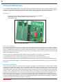
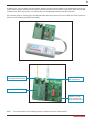
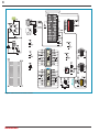
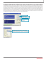
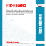
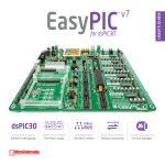
All Mikroelektronika’s development systems feature a large number of peripheral
modules expanding microcontroller’s range of application and making the
process of program testing easier. In addition to these modules, it is also
possible to use numerous additional modules linked to the development system
through the I/O port connectors. Some of these additional modules can operate
as stand-alone devices without being connected to the microcontroller.
Manual
Additional Board
PIC-Ready2
™
MikroElektronika
2
PIC-Ready2 Additional Board
The PIC-Ready2 additional board enables a .hex code to be quickly and easily loaded into PIC microcontrollers by using the PICFlash
programmer or the bootloader software. The additional board is supplied with two sockets for microcontrollers in DIP18 package, 2x5
connectors connected to the microcontroller pins, pads, srew terminal for power supply, USB connector and reset button.
Key features:
- Programming microcontrollers with the bootloader software and PICflash programmer;
- Power supply voltage in the range between 8 and 16V AC/DC; and
- Pads (PROTO board).
Figure 1: PIC-Ready2 additional board
How to connect the board?
Power supply voltage from 8 to 16V AC/DC is supplied to the additional board via the screw connector CN7. This voltage is necessary
when the microcontroller, to be placed in one of the socket on the additional board, is programmed with the bootloader software,
Figure 3. This power supply voltage is also necessary when the pads are used, i.e. when additional components are placed on the
board for the purpose of simulating the operation of some device. The PICflash programmer is connected via a 2x5 connector CN3
which is shorted with jumpers, Figure 1.
When the process of programming is performed with the PICFlash programmer, it is necessary to do the following:
1. remove jumpers from the 2x5 connector CN3 (PICFlash connector) provided on the additional board.
2. connect an IDC10 connector on the PICFlash programmer to a 2x5 connector on the additional board, Figure 2.
3. connect the PICFlash programmer to a PC using a USB cable, after which the process of loading .hex code into the microcontroller may start.
When this way of programming applies, no external power supply is needed as the board is powered by a PC through the PICFlash
programmer.
How does the board operate?
There are two ways of loading a .hex code into the microcontroller to be placed on the additional board. These are with the PICflash
programmer and the bootloader software via the microcontroller’s serial UART module. In the latter case it is necessary to turn on
the appropriate switches on the DIP switch SW1. The DIP switch SW1 is used to determine microcontroller pins to be used for the
UART communication. The position of these switches depends on the arrangement of the microcontroller pins connected to the UART
module. In order to perform programming with the bootloader software, it is necessary to use microcontroller which already has the
bootloader .hex code loaded into it. You can load the bootloader .hex into the microcotroller using the PICFlash programmer. This
should be done only once and after that you can program your microcontroller with the bootloader software via the USB connector.
Some microcontrollers get the bootloader .hex file in the Example folder along with other examples for PIC compilers (for example,
C:\Program Files\Mikroelektronika\mikroC PRO for PIC\Examples\Other\Bootloader). When the .hex code loading is complete, it is
necessary to reset the microcontroller by pressing the Reset button.
MikroElektronika
3
In addition to the .hex code loading with the bootloader software, the USB connector supplied on the additional board can also be
used to enable connection between the microcontroller and other devices that use serial UART communication. When using the USB
connector for the UART communication, it is necessary to turn on the appropriate switches on the DIP switch SW1.
2x5 connectors placed on the right side of the additional board enable easy access to the microcontroller pins. Each connector is
linked to one microcontroller port (PORTA and PORTB).
Figure 2: PIC-Ready2 additional board connected to the PICFlash programmer
Power supply voltage 8-16V AC/
DC is supplied via CN7 connector
USB connector for serial
UART communication
Pads may be used as a proto board
When the PICFlash
programmer is not used,
jumpers should be placed
over the CN3 connector pins
Figure 3: UART communication is enabled
NOTE:
For more information on the PICflash programmer’s operation refer to the PICflash manual.
MikroElektronika
4
Figure 4: Additional board connection schematic
MikroElektronika
5
The Bootloader software is integrated in all Mikroelektronika’s compilers. It is used to load a .hex code into the microcontroller
that already has the Bootloader .hex code loaded. In order to open the mikroBootloader window, it is necessary to select the
mikroBootloader option from the Tools menu within the compiler’s main window. The first thing you should do after that is to select the
port to be used for connecting the additional board to a PC. One click on the Setup Port button causes a window with options such as
port selection, baud rate selection etc. to be open, Figure 6. Close the Setup Port window and click on the Connect button within the
mikroBootloader window in order to establish connection between the Bootloader software and the PIC-Ready2 additional board. To
break this connection, click on the Disconnect button. Use the Open HEX file button in order to select a .hex file to be loaded into the
microcontroller provided on the additional board. One click on the Start bootloader button will start up the process of .hex file loading.
This process can be ceased at any time by clicking on the Stop bootloader button.
Button to select port
Button to connect/
disconnect additional board
Button to open .hex file
Button to enable/disable
bootloader
Figure 5: MikroBootloader
Baud rate depends on the rate defined in the bootloader .hex
code loaded into the microcontroller. For the bootloaders
provided with Mikroelektronika’s compilers, it is set to 9600bps
Figure 6: Port selection
MikroElektronika
MikroElektronika
If you have any questions, comments or business proposals, do not hesitate to contact us at [email protected]
If you are experiencing some problems with any of our products or just need additional information, please place your ticket at
www.mikroe.com/en/support
If you want to learn more about our products, please visit our website at www.mikroe.com
6
Mouser Electronics
Authorized Distributor
Click to View Pricing, Inventory, Delivery & Lifecycle Information:
mikroElektronika:
MIKROE-414