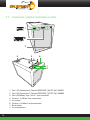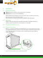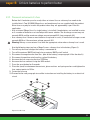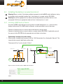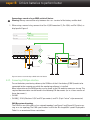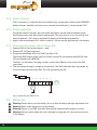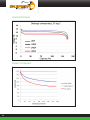
1
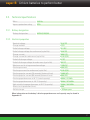
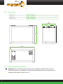
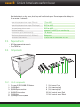
LITHIUM BATTERY
SB12V160E-ZC
13.2V/160 Ah
(2.1kW LiFePO4)
User Manual SB12V160E-ZC Lithium Iron Phosphate battery
Dear customer,
This manual contains all the information necessary to install, use and maintain the super
B SB12V160E-ZC Lithium Iron Phosphate Battery. We kindly ask of you to read this manual
carefully before using the product. In this manual, the SB12V160E-ZC battery will be referred
to as: the Li-Ion battery.
This manual is meant for the installer and the user of the Li-Ion battery. Only qualified,
certified personnel may install and perform maintenance on the Ii-Ion battery. Please consult
the index at the start of this manual to locate information relevant to you.
This is the original manual, keep it on a safe location!
Copyright© super B b.v. All rights reserved. Licensed software products are owned by super B
or its subsidiaries or suppliers, and are protected by national copyright laws and international
treaty provisions. Super B products are covered by Dutch and foreign patents, issued and
pending. Information in this publication supersedes that in all previously published material.
Specifications and price change privileges reserved. Super B is a registered trademark of
super B b.v.
For more information, or to order documents, contact:
super B b.v.
Diamantstraat 1e
7554 TA Hengelo (Ov)
The Netherlands
Tel:+31(0)748200010
Fax:+31(0)748200011
E-mail:[email protected]
www:http://www.super-b.com
2
super B Lithium batteries to perform better
Table of content
1.Introduction
5
2. Product specifications
6
1.1.
1.2.
1.3.
Product description Glossary of Terminology
Used symbols
2.1.
Product features
2.2.
General product specifications
2.3.
Technical specifications
2.3.1. Battery designation
2.3.2. Electrical properties
2.3.3.Dimensions
2.4.
Environmental conditions
2.5.
Required tools
2.6.
Components 2.6.1. List of components
2.7.
Connections, indicators and battery controls 2.7.1. Con1 (I/O Connection 4)
2.7.2. Con2 (I/O connection 7)
2.8.
Peripheral equipment
2.8.1.Obligatory
2.8.2.Optional
5
5
6
6
6
7
7
7
8
8
9
9
9
10
11
11
11
11
12
3. Safety guidelines and measures
12
4.Installation
14
3.1.General
3.2.Installation
3.3.Use
3.4.Disposal
3.5.
Safety symbols and markings on product
4.1.
General information
4.2.Unpacking
4.3.
Preparing the battery for use
4.3.1. Placement of the battery
4.3.2. Placement and removal of a fuse
4.4.
Installing the battery in an electrical circuit
4.4.1. Installing a BMS Switch off device
4.4.2. Connecting CANOpen interface
4.4.3. Connecting the battery to the load
4.4.4. Connecting a charger to the battery
4.4.5. Disconnecting a battery
4.4.6. More configuration options
12
13
13
13
13
14
14
14
14
15
16
16
17
19
21
21
22
3
5. Battery use 24
6. Inspection, cleaning and maintenance
28
7.Storage
8.Transportation
29
29
9. Disposal and recycling 30
10.Troubleshooting 11.Warranty and liability
31
33
5.1.
General information 5.2.Charging
5.2.1. Charging rate
5.2.2. Charging methods
5.2.3. Battery balancing
5.2.4. Battery equalization
5.2.5. Determining the battery’s state of charge (SoC)
5.3.
Battery use 5.3.1. Battery fault condition
5.4.
Battery Monitoring Software
5.4.1. Continuous Battery Monitoring 5.4.2. Battery History Recording
6.1.
General information
6.2.Inspection
6.3.Cleaning
6.4.Maintenance
8.0General
9.1.
4
General information
24
24
24
24
26
26
26
26
27
27
27
27
28
28
28
28
29
30
super B Lithium batteries to perform better
1. Introduction
1.1. Product description
The SB12V160E-ZC is a Lithium Iron Phosphate rechargeable battery. Potential applications
of this battery include: off grid power supply, marine power supply, medium for (renewable)
energy storage (traction) battery for vehicles. The boundaries of its use, as described in
this manual should always be upheld. The Li-Ion battery may not be used in medical or in
aviation related applications. The Li-Ion battery may not be used for any purposes other
then described in this manual. Using the battery for any other purposes will be considered
improper use and will void the warranty of the product. Super B b.v. cannot be held
responsible for any damage caused by improper, incorrect or unwise use of the product.
Read and understand this manual completely before using the product.
Super B provides a CE declaration of conformity (appendix 1) and a Certificate of Compliance
(appendix 2) for the product. In accordance with CE guidelines, a design and manufacturing
schedule is available. A Material Safety Data Sheet is also available.
The SB12V160E-ZC complies with the following council directives:
• 2006/66/EC on Environmental EU Compliance
• 2004/108/EC (December 15, 2004) on Electromagnetic Compatibility
•
•
•
•
The SB12V160E-ZC complies with the following standards:
IEC 61000-4-2, EMC Compliance
IEC 62133, Safety IEC Compliance
IEC 61960{ed2.0}, Performance IEC Compliance
IEC 62281, Transportation IEC Compliance
During the use of the product, user safety should always be ensured, so installers, users,
service personnel and third parties can safely use the product. The user must always have
access to this manual; keep it in a safe accessible location.
1.2. Glossary of Terminology
Endurance Life-cycle:
Charge cycle:
RSW:
BMS:
SoC:
T he products maximum lifespan, achieved by adhering to the
guidelines presented in this manual.
A period of use from fully charged, to fully discharged, and fully
recharged again.
Remote switch
Battery management system
State of charge
5
1.3. Used symbols
The following icons will be used throughout the manual:
! Warning! A warning indicates severe damage to the user and/or product may occur when a
procedure is not carried out as described.
! Caution! A caution sign indicates problems may occur if a procedure is not carried out as
described. It may also serve as a reminder to the user.
2. Product specifications
2.1. Product features
• Traction battery
• Lithium Iron Phosphate (LiFePO4)
-- Most safe lithium technology
-- Superior abuse tolerance
• Integrated BMS
• Glass fiber reinforced plastic (GRFP) Casing, Aluminum / PE sandwich side panels
• Terminals for 2 x 95mm2 wire connection per terminal
• Integrated fuse, 32V / 500A
• 3C continuous discharge (480A)
• CANOpen interface for battery monitoring
• Battery monitoring / History Storage
• Adaptive cell balancing
• Serial string equalization
• Serial string connection up to 1150V DC
• External BMS Relay, latching (bi-stable)
• External BMS cut-off switch, CAN controlled
2.2. General product specifications
Product name:
SB12V160E-ZC
Producer:
super B b.v.
Battery type:
Lithium Iron Phosphate (LiFePO4)
Product Lifespan:
+ /-5 to 10 years or 1000-2000 cycles at 1C charge / discharge
or 8000 cycles at C4 charge / discharge*
*The lifespan value given above is an indication. Battery lifespan dependents strongly on the
applied charging and discharging loads. For more information on the lifespan of the battery,
appendix II may be consulted.
6
super B Lithium batteries to perform better
2.3. Technical specifications
Mass:
28.3 Kg
Ingress protection rating
IP53
2.3.1. Battery designation
Battery designation:
4IFP227/415/315
2.3.2. Electrical properties
Nominal voltage
13.2V DC
Charge method
CCCV
End of charge voltage
15 V DC
End of charge voltage for endurance (cycle life)
14.6V DC
Charge current
160A (1C)
Charge current for endurance (cycle life)
52.8A (C/3)
End-of-discharge voltage
8V DC
End-of-discharge voltage for endurance (cycle life)
10V DC
Maximum serial string connection voltage
1150V DC
Discharge current
480A (3C)
Discharge current for endurance (cycle life)
52.8A (C/3)
Discharge pulse current (10 seconds) (external fuse)
1280A (8C)
Discharge pulse current (60 second) (external fuse)
800A (5C)
Discharge performance at 20 °C (rated capacity)
160Ah / 2112Wh
Discharge performance at –20 °C (capacity)
104Ah / 1372.8Wh
High rate discharge performance at 20 °C (capacity)
144Ah / 1841.4Wh
Short-circuit protection (fuse):
500A
Self discharge:
± 10% per year
More information on the battery’s discharge performance and capacity may be found in
Appendix III.
7
2.3.3. Dimensions
Height (H):
313.00 / 314.00 mm
Width (W):
413.50 / 414.50 mm
Thickness (T):
225.00 / 226.00 mm
225.0
226.0
313.0
314.0
413.5
414.5
2.4. Environmental conditions
! Warning! The Li-Ion Battery may only be used in conditions specified in this manual.
Exposing the battery to conditions outside the specified boundaries may lead to serious
damage to the product and/or the user.
8
super B Lithium batteries to perform better
Use the battery in a dry, clean, dust free, well ventilated space. Do not expose the battery to
fire or water or solvents.
Operating temperature range (Charge)
0°C to +45°C
Operating temperature range (Discharge)
-20°C to +60°C
Storage temperature range
-20°C to +60°C
Relative humidity:
Between 5 and 85 %, non condensing
Placement angle (continuously):
< 45 degrees
Maximum placement angle (< 48 hours):
90 degrees
Vibrations and shocks:
As described in UN38.3 and IEC 6228
2.5. Required tools
• M13 Hexagon socket wrench
• Fuse TORX key
2.6. Components
2
3
4
5 6
7 8
9
10 11
1
2.6.1. List of components
1.
2.
3.
4.
5.
6.
(1) super B SB12V160E-ZC Battery
(4x) M8 Bolt
(6x) M8 Spring washer
(6x) M8 Plain washer
(2x) M8 Nut
(2x) Mega Fuse 32V/500A
7. (1x) Dummy Fuse
8. (1x) Phoenix plug 4
9. (1x) Phoenix plug 7
10.(2x) Terminal cover, Red
11.(2x) Terminal cover, Black
9
2.7. Connections, indicators and battery controls
1
1 2 3 4
2
1 2 3 4 5 6 7
3
4
5
6
7
8
1.
2.
3.
4.
5.
6.
7.
8.
10
Con 1 (I/O Connection 4; Phoenix FRONT-MC 1,5/4-STF-3,81 1850877)
Con 2 (I/O Connection 7; Phoenix FRONT-MC 1,5/7-STF-3,81 1850903)
Con 3 (CANOpen; 5-pin “micro” style connector)
Terminal - (2x 95mm2 wire connection)
Fuse cover
Terminal + (2x 95mm2 wire connection)
Reset button
Fuse connections
super B Lithium batteries to perform better
2.7.1. Con1 (I/O Connection 4)
Pin1:
+, OFF
Pin2:
-, ON
Pin3:
-, OFF
Pin4:
+, ON
2.7.2. Con2 (I/O connection 7)
Pin1:
V+ max 30 Volt
Pin2:
AN_SOC (Analogue state of charge)
Pin3:
Nc (Not connected)
Pin4:
Rc, (Relay common contact)
Pin5:
Rnc, (Relay normaly close contact)
Pin6:
Rno, (Relay normaly open contact)
Pin7:
GND, (Ground)
2.8. Peripheral equipment
2.8.1. Obligatory
In order for the Li-Ion battery to be used safely, an approved external switch off device must be
installed. This should either be a relay or latching relay (bi-stable) controlled by the battery’s
BMS or a relay or latching relay controlled by a remote switch (CAN controlled). (see paragraph
4.4) Failure to install an external switch off device will void the warranty of the Li-Ion battery.
Use appropriate wire for the connection wires to ensure no overheating or unnecessary losses
occur. Consult the SAE-J378 or ISO 10133:2012 standards to determine the appropriate wire
properties. Use appropriate fuses matching the wires and load.
11
2.8.2. Optional
The Li-Ion battery can be used in combination with a number of (super B) products:
Article name
Article code
SB-GXL14B2B (latching relay)
9586 100 3105 0 SB-LIR250 (relay)
9586 100 3106 0 SB-V23130C2021A412-TE (latching relay) 9586 100 3108 0
SB MIC-C TERMINATOR RESISTOR FEMALE STD WH
9586 100 4001 0
SB MIC-C TERMINATOR RESISTOR MALE STD WH
9586 100 4002 0
SB CAN Patchcord 0.6m
9586 100 3001 0
SB CAN Patchcord 1m
9586 100 3002 0
SB CAN Patchcord 2m
9586 100 3003 0
SB CAN Patchcord 5m
9586 100 3004 0
SB CAN Patchcord 10m
9586 100 3005 0
SB CAN splitter 9586 100 3006 0
SB-RSW1
9586 100 3007 0
SB-MAS1
9586 100 3008 0
SB USB to Can
9586 100 3201 0
SB Monitor Software
9586 100 3201 0
SB API
9586 100 3203 0
SB USB to CAN/SB Monitor Software/SB API total package
Mounting bracket ZC casing
9586 300 0009 0
3. Safety guidelines and measures
3.1. General
! Warning! Keep the battery away from fire, excessive heat, water, dust and contamination
! Corrosive! Do not touch the battery’s electrolyte after leakage. If contact occurs, flush with
(lukewarm) water and seek medical assistance immediately
! Warning! Do not disassemble, crush, or puncture the battery
12
super B Lithium batteries to perform better
! Warning! Keep the Li-Ion battery away from children
! Warning! Never touch the battery contacts or allow (conductive) objects to touch the contacts
3.2. Installation
! Warning! Never use the Li-Ion battery without a properly installed BMS switch off device,
controlled by either the Li-Ion battery or a remote switch (SB-RSW)
3.3. Use
! Warning! Do not overcharge the Li-Ion battery
! Warning! Never short circuit the battery
3.4. Disposal
LI-ION
Dispose of the battery in accordance with local, state and federal laws and
regulations. Batteries may be returned to the manufacturer. Do not mix with other
(industrial) waste
3.5. Safety symbols and markings on product
A number of safety symbols and markings can be found on the product. These markings are
displayed below. Never remove these markings!
Symbol
Description
Keep the Li-Ion battery upright. Never tilt the battery more then
90 degrees.
Dispose of the Li-Ion battery in accordance with local, state and
federal laws and regulations. Batteries may be returned to the
manufacturer. Do not mix with other (industrial) waste.
LI-ION
This product, or sections of this product can be recycled
13
4. Installation
4.1. General information
! Warning! Do not disassemble, crush, or puncture the Li-Ion battery.
! Warning! Never install or use a damaged battery.
When connecting several batteries in series or parallel, always use batteries of the same
brand, type, age, capacity and state of charge.
The Li-Ion battery is one on one replaceable with AGM/GEL lead acid batteries.
4.2. Unpacking
Check the battery for damage after unpacking. If the battery is damaged, contact your
reseller or super B. Do not install or use the battery if it is damaged!
4.3. Preparing the battery for use
4.3.1. Placement of the battery
Before it is used, the Li-Ion battery must be positioned in such a way it will not move around
in its compartment during use. If necessary, the Li-Ion battery may be fixed in place by means
super B mounting brackets. The brackets can be screwed in place by means of bolts or
screws. (See Figure 1)
Figure 1. Installing the Li-Ion battery using the super B mounting brackets
14
super B Lithium batteries to perform better
4.3.2. Placement and removal of a fuse
Before the Li-Ion battery can be used, either an internal fuse or a dummy fuse needs to be
installed into it. Two 32V/500A Mega fuses and one dummy fuse are supplied with the product.
Other fuses may only be used in the product when they are approved by super B for this
application.
• Use an internal (Mega) fuse if a single battery is installed, if two batteries are installed in series
or if a number of batteries are installed parallel to one another. The discharge current may not
exceeds 500 A and the maximum voltage may not exceed 32V. (see paragraph 4.4).
• Use a dummy fuse if three or more batteries are placed in series, if maximum discharge current
exceeds 500 A or if the maximum voltage exceeds 32V.
! Warning! Always use an external fuse with the appropriate value when a dummy fuse is used.
Use the following steps to place a Mega Fuse or a dummy fuse in the battery (Figure 2):
Turn off any device or charger the battery is connected to
Turn off the external BMS (latching) relay or external BMS cut-off switch
Disconnect the negative wire from the - pole of the battery (see paragraph 4.4 for the details)
Disconnect the positive wire from the + pole of the battery
Unscrew the fuse cap using the fuse TORX key
Unscrew the fuse contacts using the M13 wrench
Press the reset button for 5 seconds
Place the (new) fuse between the contacts, place washers and spring washers and tighten the
fuse contact points to 13 Nm.
9. Fasten the fuse cap
10.Proceed to the next paragraph to read the instructions on installing the battery in an electrical
circuit
1.
2.
3.
4.
5.
6.
7.
8.
Figure 2. Install a fuse
15
4.4. Installing the battery in an electrical circuit
! Warning! Never use the Li-Ion battery without a properly installed BMS switch off device (relay
or latching relay) controlled by either the Li-Ion battery or a remote switch. (SB-RSW)
! Warning! Install the appropriate fuse before connecting the battery to other devices. (see
paragraph 4.3.2) Use an appropriate external fuse if a dummy fuse is used.
4.4.1. Installing a BMS Switch off device
An external BMS switch off device can be either installed beween the + or - terminal of the
battery and the load. This BMS switch off device can be controlled in one of two ways:
• Connect a latching relay or a normal relay to the battery’s internal driver
• Connect a latching relay or a normal relay to a remote switch (SB-RSW). If applicable, consult
the manual of the SB-RSW for the appropriate installation instructions.
Connecting a latching relay to the battery:
1. When using a latching relay, connect it to Con 1 (I/O Connection 4) as displayed in Figure 3. The
internal driver controls both high and low side.
The output of Con 1 can be found in Table 1.
Charger / Load
Battery terminal
Latching relay
Load
Battery terminal
13.2V / 250A
DC Charger
con 1
1
2
3
4
GND
Figure 3. Connect a latching relay as BMS switch off device
Con 1 output (12V DC)
Continuous
2,7 A
100ms pulse
15 A
Table 1.
16
GND
super B Lithium batteries to perform better
Connecting a normal relay as BMS switch off device:
! Warning! Always connect the relay between the + or - terminal of the battery and the load.
1. When using a normal relay, connect it to Con 2 (I/O Connection 7), Pin 4 (Rc) and Pin 5 (Rnc) as
displayed in Figure 4
Pin 4
250 VDC
5A
V max
A max
Inside
Battery
1
2
3
Rc
4
Rnc
5
Rno
6
7
Relay
con 2
Battery terminal
Load
13.2V / 250A
Fuse 5A
Charger / Load
Fuse 5A
Outside
Battery
Rc
Rno
DC Charger
Battery + or - Terminal
VDC
GND
GND
GND
GND
Figure 4. Connect a normal relay as BMS switch off device
4.4.2. Connecting CANOpen interface
To use the battery monitoring software, the CAN bus of the Li-Ion battery (CON 3) needs to be
connected to the computer on which the monitoring software is installed.
More information on the CANOpen bus can be found at the CiA website: www.can-cia.org. The
required documentation can be found in the following CiA documents: (or in a future version of
these documents.)
• CiA 301
• CiA 303_1 V1.8.0; Sections 5 (AC and DC parameters) and 7.2: (5-pin “micro” style connector)
CAN Bus network topology
The CAN Bus must be used in a bus network topology (see Figure 5 and Figure 6). Do not use a
ring- or a star topology. The CAN specifications restrict the Bus length/Bus speed. Displayed in
Table 2 is an overview of these restrictions.
17
Load
External fuse
Number of batteries in series
12-42VDC / 5A
Terminator
SB-RSW
DC Charger
CANOpen
CANOpen
Terminator
Terminator
Max. 1.5 Meter
CAN/USB
GND
Terminator
Monitoring Software
GND
Figure 5. CAN Bus network topology
Bit rate
Bus length (L)
Max. stub length (S)
Accumulated stub length
1 Mbit/s
25 m
1.5 m
7.5 m
800 kbit/s
50 m
2.5 m
12.5 m
500 kbit/s
100 m
5.5 m
27.5 m
250 kbit/s*
250 m
11 m
55 m
125 kbit/s
500 m
22 m
110 m
50 kbit/s
1000 m
55 m
275 m
20 kbit/s
2500 m
137.5 m
687.5 m
10 kbit/s
5000 m
275 m
1375 m
Table 2. CAN bus speed
The default speed of the Can BUS is 250 kbit/s.
A high speed bus requires termination at the two ends of the bus. The CAN to USB converter
can either be connected at one end of the bus (with termination) or in the middle of the bus
with no termination; termination should then be placed at the endnodes of the bus line.
Termination Resistors
Use termination resistors at the end nodes to impede reflections on the line. The value of this
resistor should be +/- 120 ohms. More information on termination resistors can be found in
CiA document 303_1 V1.8.0, section 5.
18
super B Lithium batteries to perform better
CAN bus power
Due to the galvanic separation between the battery monitoring hardware and the battery, an
external power supply is needed for the CAN bus. The CAN bus can be powered by either the
SB-MAS or the SB-RSW. If the SB-MAS or the SB-RSW cannot be used, the CAN bus can
be powered through Con 2 (I/O Connection 7). This situation may occur when a USB-to CAN
interface is directly connected to the battery. (Figure 6)
1. Connect Pin 1 of Con2 to the + terminal of the battery
2. Connect Pin 7 of Con2 to the - terminal of the battery
Terminator
Male
V+ Battery
Fuse 5A
1
CANOpen
2
3
4
5
6
7
con 2
CAN/USB
Terminator
Female
Monitoring Software
V- Battery
Figure 6. Use Con2 to power the CAN bus
4.4.3. Connecting the battery to the load
! Warning! Ensure you have completed all the previous steps described in chapter 4 before
connecting the battery to the load.
1.
2.
3.
4.
Slide the terminal covers over the connection wires
Connect the + terminal of the battery to the - or A2 terminal of the relay (Figure 7; 1)
Connect the load or charger to the + or A1 terminal of the relay
Connect the - terminal of the battery. Do not connect the - terminal first as this may lead to
short circuits (Figure 7; 2)
5. Ensure both contacts are tightened to 20 Nm
6. Place the terminal covers over the terminals (Figure 8)
19
2
1
(Load/Charger)
(Latching) Relay
Figure 7. Connecting the battery to the load
Load/Charger
(Latching) Relay
Figure 8. Securing the terminal covers
Bi-stable Relay
Battery terminal
Load
13.2V / 250A
GND
Figure 9. Connecting the battery to the load
20
GND
super B Lithium batteries to perform better
4.4.4. Connecting a charger to the battery
! Warning! Ensure you have completed all the previous steps described in chapter 4 before
connecting the battery to the charger.
1. Connect the charger behind the BMS switch off device as displayed in Figure 10
2. Disconnect the charger from the mains and the battery if it is not used for a long time
Bi-stable Relay
Load
Battery terminal
13.2V
DC Charger
GND
GND
Figure 10. Connecting the charger
4.4.5. Disconnecting a battery
1.
2.
3.
4.
Turn off any device or charger the battery is connected to
Turn off the external BMS (latching) relay or external BMS cut-off switch
Disconnect the negative wire from the - terminal of the battery
Disconnect the positive wire from the + terminal of the battery
21
4.4.6. More configuration options
Other configurations to connect the battery are also possible: see Figure 11 - Figure 16
Bi-stable Relay
Relay
Load
Load
13.2V / 500A
13.2V / 500A
Battery terminal
Fuse 5A
Rc
Rnc
Bi-stable Relay
Rc
Rnc
GND
GND
Figure 11. Example 1
GND
Figure 12. Example 2
Relay
Bi-stable Relay
Load
Bi-stable Relay
Load
13.2V / 500A
Fuse 5A
Rc
Rc
Rnc
Rnc
26.4V / 250A
GND
GND
GND
Figure 13. Example 3
Relay
Load
External Fuse (500A)
Fuse 5A
79.2V
GND
Figure 15. Example 5
22
Figure 14. Example 4
6 Batteries in series (6x13.2=79.2V)
Rc
Rc
Rc
Rnc
Rnc
Rnc
GND
super B Lithium batteries to perform better
External fuse
56 Batteries in series (56x13.2≈750V)
12-42VDC / 5A
SB-RSW
Terminator
CANOpen
CANOpen
Terminator
Terminator
8 Strings in parallel)
External fuse
56 Batteries in series (56x13.2≈750V)
12-42VDC / 5A
750 V
SB-RSW
CANOpen
CANOpen
Terminator
Terminator
CAN/USB
Terminator
Monitoring Software
GND
Figure 16. Example 6
23
5. Battery use
5.1. General information
! Warning! Keep the Li-Ion battery away from children.
5.2. Charging
! Warning! Never overcharge the Li-Ion battery, this will permanently damage the battery. Always
use a charger which automatically halts the charging process when the battery is full.
! Warning! Stop the charging process if the battery gets too hot during charging (>55-60°c)
! Warning! Never charge a battery with a charging current larger than 1C as this will damage the
battery.
! Caution! Disconnect the charger from the mains and the battery if it is not used for a long time.
! Caution! To preserve the lifespan of the Li-Ion battery use a super B charger or a charger
approved by super B. The use of other chargers, such as lead-acid chargers will shorten the
lifespan of the Li-Ion battery. AGM / GEL chargers may be used if the charge voltages of the
different charge states don’t exceed the charge voltage limits of the battery.
1. Connect the charger to the battery as described in paragraph 4.4.
2. Charge the battery whenever the voltage of the battery drops below 10 V or if the state of charge
drops below 20% to preserve the lifespan of the battery.
5.2.1. Charging rate
Lithium Iron Phosphate batteries can be charged much faster then traditional lead acid
batteries. Displayed in Table 3 are the charge times for the Li-Ion battery at different charge
currents. Always use the indicated charge current and end of charge voltage during charging.
Consult paragraph 5.2.2 for the appropriate charging methods.
Time
Charge current
End of charge voltage
Maximum
1 hour
1C (160A)
15 V DC
Endurance lifecycle
3 hours
C3 (52.8)
14,6V DC
Table 3. Charging rates at different charge currents
5.2.2. Charging methods
Two charging methods may be used to charge the Li-Ion battery:
Constant voltage / constant current charge (see Figure 17)
1. Set the charge current and end of charge voltage to the values described in paragraph 5.2.1.
2. Set the charger to terminate charging when the charge current drops below 3% of the
recommended charge current. (3% of 160A = 4.8A)
24
super B Lithium batteries to perform better
18
Stage 1
17
16
14.6
Stage 2
Topping charge
Constant current charge
15
14
13
12
U(V) / I(A)
11
10
9
Charge current C3
8
7
6
5
4
3
Terminate Charge
when current < 3% of
recommended charge current
2
1
0
0
20
40
60
80
100
120
140
160
180
200
220
240
T (Minutes)
Figure 17. Constant voltage/Constant current charge
Constant voltage / constant current charge, using an AGM/GEL battery charger algorithm
(see Figure 18)
Super B recommends using this charging method since it aids in balancing the battery,
prolonging the lifespan of the battery. This charging algorithm is also used for AGM/GEL
batteries.
1. Set the charge current and end of charge voltage to the values described in paragraph 5.2.1.
2. Set the charger to go to float mode (13.7V - 13.9V) when the charge current drops below 3%
of the recommended charge current. (3% of 160A = 4.8A)
18
Stage 1
17
Constant current charge
16
14.6
Stage 2
Stage 3
Topping charge
Float charge
15
14
13
12
U(V) / I(A)
11
10
9
Charge current C3
8
7
6
5
4
3
2
1
0
Charge during float mode ~ 4.8 A
0
20
40
60
80
100
120
140
160
180
200
220
240
T (Minutes)
Figure 18. Constant voltage/Constant current charge with AGM/GEL battery charger algorithm
25
5.2.3. Battery balancing
• The Li-Ion battery is automatically balanced when the charger goes to float mode (AGM/GEL
battery charger algorithm) and no current is drawn from the battery. (see paragraph 5.2.2)
5.2.4. Battery equalization
During the batteries lifespan, the cells within the battery may be unbalanced due to high
discharge currents and short float charge periods. This may result in a loss of capacity and
overcharged cells. Cells may be equalized by means of the following procedure:
1. Apply a constant voltage of 14.2 and a current of < 2A to manually equalize the Li-Ion battery.
5.2.5. Determining the battery’s state of charge (SoC)
1. Connect Pin1 of Con2 to the battery’s + pole
2. Connect Pin 7 of Con2 to ground
3. Determine the voltage at Pin 2 of CON2 (see Figure 19)
The analog SoC output ranges from 0 to 10 volt, in which 0V corresponds with 0% SoC and
10V corresponds with 100% SoC.
The SoC is an indication. Charging currents smaller then 100mA are not used in the SoC
calculation.
4. Take the battery through a complete charge cycle if the SoC indication does not provide an
accurate representation of the SoC. This will recalibrate the SoC.
V+
Fuse 5A
1
2
3
4
5
6
7
con 2
V
GND
GND
Figure 19. Determining the batteries SoC
5.3. Battery use
!
!
!
!
26
Warning! Do not short circuit the battery, this may lead to battery damage, explosion or fire.
Warning! Never touch the terminals of the battery.
Warning! Always use a BMS switch off device when connecting the battery to a load.
Warning! Always remain within the limits indicated in paragraph 2.3.2 during the use of the
Li-Ion battery.
super B Lithium batteries to perform better
5.3.1. Battery fault condition
During battery use the external BMS switch off device may be triggered, disconnecting
the battery from all loads and the charger. This shut off is the result of a fault condition. To
identify and resolve this fault condition, chapter 10 may be consulted. The Battery Monitoring
software may also be used to identify a fault condition. (see paragraph 5.4)
5.4. Battery Monitoring Software
Battery monitoring software offers the possibility to continuously monitor a number of battery
properties through sensors within the Li-Ion battery. It also enables one to download a
complete recording of the battery’s properties over time (see paragraph 5.4.2).
The Battery Monitoring software and the hardware needed to connect the battery to the
computer is not included with the Li-Ion battery. An overview of these products is given in
paragraph .
5.4.1. Continuous Battery Monitoring
•
•
•
•
•
The Battery monitoring software is able to continuously monitor and relay the following
battery properties:
Battery serial number
Battery voltage
State of charge
Charge / Discharge current
Battery status (Alarms and Warnings)
5.4.2. Battery History Recording
The complete battery history can be downloaded with the battery monitor software. This
recording can only be accessed by a reseller or super B for evaluation.
27
6. Inspection, cleaning and maintenance
6.1. General information
! Warning! Never attempt to open or dismantle the battery! The inside of the battery does not
contain serviceable parts.
1. Disconnect the Li-Ion battery from all loads and charging devices before performing cleaning
and maintenance activities. (see paragraph 4.4.5)
2. Remove the fuse or dummy fuse before cleaning and maintenance activities. (see paragraph
4.3.2)
3. Place the included protective caps over the terminals before cleaning and maintenance
activities to avoid the risk of contacting the terminals.
6.2. Inspection
1. Inspect for loose and/or damaged wiring and contacts, cracks, deformations, leakage or
damage of any other kind. If damage to the battery is found, it must be replaced. Do not
attempt to charge or use a damaged battery. Do not touch the liquid from a ruptured battery
2. Observe and note the run time that a new, fully-charged battery provides for powering your
product. Use this new battery run time as a basis to compare run times for older batteries.
The run time of the Li-Ion battery will vary depending on the products’ configuration and the
application it is used for.
3. Routinely check the battery’s charge status. Lithium Iron Phosphate batteries continue to
slowly self-discharge (10% per year) when not in use or while in storage.
4. Carefully monitor batteries that are approaching the end of their estimated life.
5. Consider replacing the battery with a new one if you note either of the following conditions:
-- The battery run time drops below about 80% of the original run time.
-- The battery charge time increases significantly.
6.3. Cleaning
If necessary, clean the Li-Ion battery with a soft, dry cloth. Never use liquids, solvents, or
abrasives to clean the Li-Ion battery.
6.4. Maintenance
The Li-Ion battery is maintenance free. Charge the battery to approximately 50% of its
capacity at least once every 2 years to preserve the battery’s capacity.
28
super B Lithium batteries to perform better
7. Storage
Follow the storage instructions in this manual to optimize the lifespan of the battery during
storage. If these instructions are not followed and the Li-Ion battery has no charge remaining
when it is checked, consider it to be damaged. Do not attempt to recharge or use it. Replace
it with a new battery.
1.
2.
3.
4.
5.
6.
7.
Remove the fuse from the battery during storage. (See paragraph 4.3.2)
Disconnect the Li-Ion battery from all loads and, if present, the charging device.
Place the terminal covers over the battery’s terminals during storage.
Store the battery in a cool and well ventilated space.
Avoid exposure of the battery to sunlight and/or UV radiation.
Charge or discharge the battery to 50% of its capacity before storage.
Charge the battery to approximately 50% of its capacity at least once every 2 years.
8. Transportation
8.0 General
Always check all applicable local, national, and international regulations before transporting
a Lithium Iron Phosphate battery.
Transporting an end-of-life, damaged, or recalled battery may, in certain cases, be
specifically limited or prohibited.
The transport of the Li-Ion battery falls under hazard class UN3480, class 9. For transport over
water, air and land, the battery falls within packaging group PI965 Section I.
Use Class 9 Miscellaneous Dangerous Goods and UN Identification labels
for transportation of lithium ion batteries which are assigned Class 9. Refer
to relevant transportation documents. Lithium and lithium ion cells and
batteries are regulated in the U.S. in accordance with Part 49 of the Code
of Federal Regulations, (49 CFR Sections 105-180) of the U.S. Hazardous
Materials Regulations.
Visit www.iata.org for the complete transport regulations and packing instructions for this
product. The relevant information for Lithium batteries can be found under “Programs” >
“Cargo” > “Dangerous goods (HAZMAT)” .
29
9. Disposal and recycling
9.1. General information
Always discharge the battery before disposal. Use electrical tape or other approved covering
over the battery connection points to prevent short circuits.
Battery recycling is encouraged. Dispose of the battery in accordance with local, state and
federal laws and regulations. Batteries may be returned to the manufacturer.
USA & Canada:
Lithium Iron Phosphate batteries are subject to disposal and recycling regulations that vary by
country and region. Always check and follow your applicable regulations before disposing of
any battery. Contact Rechargeable Battery Recycling Corporation (www.rbrc.org) for U.S.A. and
Canada, or your local battery recycling organization.
EC
Waste must be disposed of in accordance with relevant EC Directives and national, regional
and local environmental control regulations. For disposal within the EC, the appropriate code
according to the European Waste Catalogue (EWC) should be used.
Other
Many countries prohibit the disposal of waste electronic equipment in standard waste
receptacles.
30
super B Lithium batteries to perform better
10. Troubleshooting
Problem
The capacity
of battery has
decreased
Possible reason
Solution
The cells within the battery are
not properly balanced, causing
them to discharge at different
rates.
Connect the Monitor Software to
the battery to verify the status of the
battery.
If the battery status “balancing
required” is active, follow the
procedures described in paragraphs
5.2.3 and 5.2.4 to balance the cells
within the battery.
If no difference is found, the lost
capacity is due to battery aging. This
process cannot be reversed.
The battery does
not provide a
charge
The fuse of the battery is not
installed
/ the battery
cannot be
charged
The fuse in the battery is broken
Install the fuse; follow the procedures
described in paragraph 4.3.2
Disconnect all loads and chargers,
check and correct for short circuits
and defects. Then replace the fuse;
follow the procedures described in
paragraph 4.3.2
The reset button was not pressed
for 5 seconds after the installation
Press the reset button for 5 seconds.
of the fuse or after a fault
condition.
Batteries connected in series may Check the series for defective
fail to charge if a defective battery batteries. If a defective battery is
is present in the series.
found, replace it.
The battery has been discharged
to deeply causing the battery
management system to trigger the
external switch off device. The
BMS is now in “fault condition”.
Disconnect all loads and connect a
charger to the battery. Then press the
reset button for at least 5 seconds
to resolve the “fault condition”. (The
reset button can be found in the fuse
compartment; see paragraph 2.7.)
31
Problem
A ticking sound
can be heard
from within the
battery
32
Possible reason
Solution
The battery has been
overcharged, causing the battery
management system to trigger the
external switch off device. The
BMS is now in “fault condition”.
Disconnect the charger from the
battery and press the reset button for
at least 5 seconds to resolve the “fault
condition”. (The reset button can be
found in the fuse compartment; see
paragraph 2.7.)
The batteries cells have has
become unbalanced. During
charging one or more cells
overcharge, causing the battery
management system to trigger the
external switch off device. The
BMS is now in “fault condition”.
Disconnect the charger from the
battery and press the reset button for
at least 5 seconds to resolve the “fault
condition”. (The reset button can be
found in the fuse compartment; see
paragraph 2.7.) Drain the battery,
then equalize the battery’s cells as
described in paragraph 5.2.4.
The battery has overheated
causing the battery management
system to trigger the external
switch off device. The BMS is
now in “fault condition”.
Disconnect the charger and all loads
and wait for the battery to cool down.
Then press the reset button or at
least 5 seconds to resolve the “fault
condition”. (The reset button can be
found in the fuse compartment; see
paragraph 2.7.)
The Battery Management System
has detected an error and is trying
to trigger an external switch off
device to disconnect from the
load/charger. The BMS uses an
internal relay to do so. However
no external switch off device is
connected (to the BMS), causing
the internal relay to keep firing.
Immediately disconnect the battery
from the load and install a switch
off device; see paragraph 4.4.1,
Then press the reset button for at
least 5 seconds to resolve the “fault
condition”.
super B Lithium batteries to perform better
11. Warranty and liability
11.1 Upon delivery, the customer is obliged to immediately verify whether the products have
been damaged during transport. If its not, the customer must notify Super B of such transport
damage as soon as possible, in any event no later than within three (3) days of delivery, by
means of an accurate, written statement, stating the damage and where possible a photograph.
11.2 If the customer demonstrates that the products do not conform to the agreement, Super B
has the option to repair and/or replace the relevant products by new products when returned
and/or to refund the invoice value, exclusive of any dispatch costs.
11.3 If the customer is a private individual not acting for or on behalf of any company or
business, the customer has the right to return the product to Super B within seven (7) days of
delivery. In this event, goods returned are only accepted if the product and its original packaging
are free of damage, while the dispatch costs for returning the goods shall be at the customer’s
expense.
11.4 Super B shall use its best endeavors to manufacture reliable and safe products and to
deliver these to the customer.
11.5 Super B grants a three year limited warranty for manufacturing faults. ‘Manufacturing
faults’ do not include damage caused as a result of (a) general tear and wear, (b) short circuit,
(c) overcharging, (d) deep discharging, (e) a wrongful connection to engines and other devices,
(f) the absence of an approved and properly installed external BMS relay or other switch off
device (g) any other wrongful use contrary to the user instruction; and (h) any use contrary to
the product specifications of that product.
11.6 Any liability to the customer in any case ends if the customer fails to notify Super B of the
existence of the defect within three (3) days of having discovered the defect, in writing, in order
to enable Super B to investigate this.
11.7 Any liability of Super B for damage suffered by the customer is in any case limited to the
invoice amount of the relevant products. Super B can never be held liable for consequential
damage or losses of profits, unless such damage has been caused by gross negligence or willful
misconduct of Super B.
11.8 To the extent that a court determines that the limitation of liability as meant in clause 11.7
cannot be invoked against a particular claim for damages by the customer, Super B’s liability
33
for loss of property, damage to property and bodily injury (including death) caused by the
application of those particular Super B products shall in any event be limited to the amount
actually paid out by Super B’s insurance company to Super B in accordance with the
insurance cover of that insurance policy for that particular type of damage. Super B has
taken out insurance against certain risks, namely for the application of Super B products in
land vehicles and in aviation, respectively, each as described in the respective insurance
policies. These policies contain a usual limitation of insurance payment to be paid out to
Super B if, and to the extent that, the event is a covered event.
34
super B Lithium batteries to perform better
Appendix I.
EC Declaration of conformity
super B b.v.
Diamantstraat 1e, 7554 TA, Hengelo, the Netherlands
+31 (0) 74-8200010, www.super-b.com
November 7, 2012
EC Declaration of Conformity
Product Number/Name/Description:
SB12V160E-OC (Lithium Ion Battery) 13.2V /160Ah /2122Wh (Energy/TractionBattery)
The undersigned hereby declares, on behalf of super B b.v. Hengelo, the Netherlands, that
the above-referenced product, to which this declaration relates, is in conformity with the
provisions of:
• Council Directive 2006/66/EC, Environmental EU Compliance
• Council Directive 2004/108/EC (December 15,2004) on Electromagnetic Compatibility
•
•
•
•
European standards used:
IEC 61000-4-2, EMC Compliance
IEC 62133, Safety IEC Compliance
IEC 61960{ed2.0}, Performance IEC Compliance
IEC 62281, Transportation IEC Compliance
The Technical Construction File required by this Directive is maintained at the corporate
headquarters of super B b.v.,
Diamantstraat 1e, 7554TA, Hengelo, the Netherlands.
M.H. Doornekamp
CEO
35
Appendix II. Certificate of Compliance
super B b.v.
Diamantstraat 1e, 7554 TA, Hengelo, the Netherlands
+31 (0) 74-8200010, www.super-b.com
November 7, 2012
Certificate of Compliance
Product Number/Name/Description:
SB12V160E-OC (Lithium Ion Battery) 13.2V /160Ah /2122Wh (Energy/TractionBattery)
The undersigned, on behalf of super B, does hereby certify that the product listed above is
compliant to:
a) The testing requirements for Lithium Batteries in Section 38.3; Part III; of the UN
Recommendations on the TRANSPORT OF DANGEROUS GOODS, Manual of Tests and
Criteria, Fourth revised edition;[ST/SG/AC.10/11/Rev.4].
b) IEC 62281, Transportation IEC Compliance
c) SP 230, Special provision
d) SP 188 / PI965, Part II IATA , Packing instructions
e) Council Directive 2006/66/EC, Environmental EU Compliance
f) Council Directive 2004/108/EC (December 15,2004) on Electromagnetic Compatibility
g) IEC 62133, Safety IEC Compliance
h) IEC 61000-4-2, EMC Compliance
i) IEC 61960{ed2.0}, Performance IEC Compliance
M.H. Doornekamp
CEO
super B b.v.
36
super B Lithium batteries to perform better
Appendix III. Performance Graphs
Depth of Discharge v/s Cycle life
Temperature performance
37
Load performance
Peukert component
38
super B Lithium batteries to perform better
39
For more information, or to order documents,
contact:
super B b.v.
Diamantstraat 1e
7554 TA Hengelo (Ov)
The Netherlands
Tel:+31(0)748200010
Fax:+31(0)748200011
E-mail:[email protected]
www:http://www.super-b.com
LI-ION