1
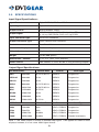
DVI-DUser
FiberGuide
Optic Cable
DVI to VGA Scaler/Converter
DVI-3120a
Table of Contents
Section
Page
1.0 Introduction. . . . . . . . . . . . . . . . . . . . . . . . . . . . . . . . . . . . . . . 1
2.0 Specifications. . . . . . . . . . . . . . . . . . . . . . . . . . . . . . . . . . . . . 3
3.0 Checking Package Contents. . . . . . . . . . . . . . . . . . . . . . . . . 4
4.0 Connecting the Hardware . . . . . . . . . . . . . . . . . . . . . . . . . . . 4
5.0 Operating The Unit. . . . . . . . . . . . . . . . . . . . . . . . . . . . . . . . . 5
6.0 Troubleshooting. . . . . . . . . . . . . . . . . . . . . . . . . . . . . . . . . . . 7
7.0 Limited Warranty. . . . . . . . . . . . . . . . . . . . . . . . . . . . . . . . . . . 8
8.0 Regulatory Compliance. . . . . . . . . . . . . . . . . . . . . . . . . . . . . 8
1.0
INTRODUCTION
Thank you for purchasing this DVI-3120a DVI to VGA Converter/Scaler from
DVIGear. The DVI-3120a is designed to convert digital DVI input signals to analog
RGB (VGA) output signals. Our professional video conversion products have
been serving the industry for several years. DVIGear offers a full line of high
quality Video Scalers, Scan Converters, Analog-Digital Converters and DVI/HDMI
Converters, as well as Signal Switchers and Distribution Amplifiers.
1.1
Liability Statement
Every effort has been made to ensure that this product is free of errors. DVIGear
cannot be held liable for the use of this hardware or any direct or indirect
consequential damages arising from its use. It is the responsibility of the user of
the hardware to check that it is suitable for his/her requirements and that it is
installed correctly. All rights reserved. No parts of this manual may be reproduced
or transmitted by any form or means electronic or mechanical, including
photocopying, recording or by any information storage or retrieval system without
the written consent of the publisher.
DVIGear reserves the right to revise any of its hardware and software following its
policy to modify and/or improve its products where necessary or desirable. This
statement does not affect the legal rights of the user in any way.
All third party trademarks and copyrights are recognised. The DVIGear logo is a
registered trademark of DVIGear, Inc. All other trademarks are the property of their
respective holders.
1.2
•
•
•
•
•
•
•
•
•
•
•
Features
Ultra-Compact, High Performance Units
Converts DVI Inputs to RGB Outputs
The input may be DVI or HDTV signals in RGBHV, YPbPr or YCbCR data
bitstream via a 24 pin DVI connector
The output may be Analog VGA, or HDTV in the format of analog RGBHV
or YPbPr via an HD15 VGA connector
Automatic Detection of Input Resolution
DVI input allows low loss conversion of signals
48Mb Frame Memory
Output Picture Adjustments for: Brightness, Contrast, Color and H/V Position
On-Screen Display for Setup and Adjustment
Rugged Metal Case
Locking DC Power Connector for Security
-1-
1.3
Getting the Best Results
There are many factors affecting the quality of results when scaling video signals.
Some basic precautions will ensure the best possible performance from your
Video Scaler.
Output Display Device – The quality of the output signal will depend largely upon
the type and quality of display device used. For instance, some video projectors
just look better than others.
Using Native Resolution – It is always best to set the output resolution of the
scaler to the native resolution and refresh rate of the display device. This allows
our scaler to do most of the work, which usually results in a superior picture.
Distance between the Video Scaler and the Display Device – This plays a
major role in the final result. Long distances are possible, but special measures
should be taken in order to avoid cable losses. These include using high quality
(coax-type) VGA cables and Premium DVI Cables. Line amplifiers may also be
necessary.
Output Connection Cables – Low quality cables are susceptible to interference.
They degrade signal quality due to poor matching and cause elevated noise levels.
Therefore, cables should be of the best quality. Coax-type computer cables are
recommended because of their superior internal shielding characteristics.
Interference from Nearby Electrical Devices – These can have an adverse effect
on signal quality. For example, an older computer monitor often emits very high
electromagnetic fields that can interfere with the performance of video equipment in
its proximity.
-2-
2.0 SPECIFICATIONS
Input Signal Specifications:
Input Format
Digital RGBHV, YPbPr or YCbCr
Input Signal
Digital RGB Data Bitstream
Output Format
Analog RGBHV, YPbPr
Output Signal
RGBHV: 0.7 V p-p, 75Ω , H/V: 3 to 5 p-p TTL,
Y: 1 V p-p 75Ω, Pb/Cb, Pr/Cr: 0.7 V p-p 75Ω
Input Connector Type
24 Pin DVI Connector
Output Connector Type
HD15 Female VGA Connector
Control
Front Panel Buttons
Information Display
On Screen Display
Video Adjustments
Brightness, Contrast, Color, H and V Position
Weight
1.5 lbs (680 grams)
Dimensions – HxWxD
1” x 7” x 4” (25 x 175 x 100 mm)
Power Source
100~240VAC to [email protected] In-Plug Switching Adapter
Output Signal Specifications:
PC Resolutions
Vertical Rate
Format
Scan Type
VGA
640x480
60,72,75,85 Hz
RGBHV
Progressive
VESA85
640x480
85 Hz
RGBHV
Progressive
VGA70
720x400
70 Hz
RGBHV
Progressive
SVGA
800x600
60,72,75,85 Hz
RGBHV
Progressive
XGA
1024x768
60,70,75,85 Hz
RGBHV
Progressive
MAC
1152x864
70,75 Hz
RGBHV
Progressive
WXGA
1280x768
60 Hz
RGBHV
Progressive
1280A
1280x960
60 Hz
RGBHV
Progressive
SXGA
1280x1024
60,75 Hz
RGBHV
Progressive
HDTV Resolutions
Vertical Rate
Format
Scan Type
480p
720x480
60Hz
YPbPr, RGBHV
Progressive
576p
720x576
50Hz
YPbPr, RGBHV
Progressive
720p
1280x720
50,60Hz
YPbPr, RGBHV
Progressive
1080i
1920x1080
50,60Hz
YPbPr, RGBHV
Pseudo Interlaced (1)
Note 1 - The 1080i Output is actually a doubled 540p signal. It will appear as 1080i on most
displays; however, it is not a true 1080i signal format.
-3-
3.0 CHECKING PACKAGE CONTENTS
Before attempting to use this unit, please check the packaging and make certain
the following items are contained in the shipping carton:
• DVI-3120a DVI to VGA Scaler/Converter
• 100-240VAC AC/DC Power Adapter
• User Guide
• User Guide
Note: Please retain the original packing material should the need ever arise to return the
unit. If you find any items are missing, contact your reseller or DVIGear immediately. Please
have the Model Number, Serial Number and Invoice Number available for reference when
you call.
4.0 CONNECTING THE HARDWARE
The first step is to connect a video source to the input of the Scaler and to connect
its output to a display device. Below you’ll find drawings of the unit showing the
locations of the input, output and power connectors.
DVI INPUT
PC/HD OUTPUT
DC 5V
480p
MENU
+
+
C
XGA
-
DVI-3120a Input / Output Panels
4.1
Connecting the Input
The DVI-3120a can accept both PC and HDTV inputs in the DVI format. When
connecting a DVI format input, use the provided DVI cable. The DVI-3120a will
automatically detect the mode and resolution of the PC/HDTV input.
4.2
Connecting the Output
The DVI-3120a Video Scaler can output a wide range of RGB Analog resolutions.
Be sure to use a high quality HD15/HD15 (VGA) cable to connect this product to
a display device. If you wish to connect this product to an Analog HDTV display
device, please use a high quality HD15 to Component Video (3x RCA) adaptor
cable (p.n: DVI-VC02, DVI-VC06 or DVI-VC12).
Note: Proper signal levels are very important to the operation of this product. If improper
operation of the unit occurs and the unit has power, the most likely cause of the problem is
high or low signal levels, use of a low quality cable, or the use of a wrong input cable.
-4-
4.3
Connecting Power to the Unit
This unit is shipped with an Plug-In Power Adapter that converts 100~240VAC@
50-60Hz to 5VDC. Connect the DC Output Cord from the Power Adapter to the
back of the unit and then plug the Power Adapter into an AC power receptacle.
When AC power is applied in this fashion, the Power LED indicator will illuminate.
5.0 OPERATING THE UNIT
The Scaler is controlled via three buttons with status indicated by an On Screen
Display.
PC/HD OUTPUT
480p
MENU
•
•
•
XGA
+
Menu Button: This Button displays the Menu Options via the On Screen
Display on the display device connected to the output.
+ and – Buttons: These Buttons allow navigation within the Menu and
adjustments of the parameters available.
XGA Reset: Simultaneously depressing the – and + buttons returns
settings to factory defaults and sets the output to XGA@60 Hz.
Pressing the Menu Button results brings up the Initial or Main Menu. Move the
cursor to the desired setup option by using the + and – buttons. Press the Menu
Button again to call up that option.
Input Set up
Output Set up
Picture Adjust
HV Adjust
OSD Adjust
System Information
Auto Adjust
Exit
Once the desired option is reached and selected, a new Menu will appear and
you once again use the + & – Keys to select the parameter you wish to change
or adjust.
-5-
5.1
OSD Menus
If you select the first item on the main menu, Input Set up, a secondary menu will
show the following items:
5.1.1 Input set up – When it is selected, a simple, two-selection sub menu will
appear.
This menu allows you to manually select the type of input you are feeding to the
scaler. You can select either YPbPr or RGB as the input type. Selecting the wrong
type of input will cause unpredictable results on the output.
Pressing the + or – buttons to select the input type, press menu to save your
selection, press + and – as required to navigate to the Exit and, once there, press
Menu again to exit this menu.
5.1.2 Output set up – When Output Set Up is selected, a new sub-menu
appears. This OSD choice will give you a display showing all the possible output
resolutions and formats. Use the + and – buttons to navigate to your choice, pres
the menu key to save your choice then use the + and – buttons again to navigate
to the exit command and press the menu button to exit the OSD display
5.1.3 Output Adjustments When in DVI-D Mode:
Picture Adjust – When the Picture Adjust Menu is selected, the following adjust
parameters will appear on the OSD:
Contrast
50
Bright
70
Color
40
Reset
Exit
Use the + and – buttons to choose the desired parameter, press Menu to select
and then use + or – to increase or decrease the value. Press Menu to save the
value. When finished with all adjustments, use the + and – buttons to move to Exit,
then press Menu to exit the routine.
-6-
5.1.4Menu Ranges and Defaults
The adjustment range and factory preset value as follows:
Value
Contrast
Bright
Color
Range
0~255
0~255
0~255
Default Value
047
102
064
Note: Select reset to reset all adjustment back to the factory preset value.
HV adjust - When selected, the following sub-menu appears.
H-position
64
V-position
42
Use the + and – buttons to adjust the best horizontal and vertical position of the picture.
OSD adjust – When this mode is selected, you can adjust the Horizontal and
Vertical position of the OSD menu.
System information – When selected, this shows the input/output resolutions and
their vertical refresh rate on the screen.
Auto adjust – When selected, the DVI-3120a will automatically adjust all the
parameters to the factory presets.
Exit – Select to exit from the current menu page.
Notes:
•
•
•
The default output resolution of the DVI-3120a is XGA@60 Hz.
The unit has non-volatile memory and memorizes all your setting before
power off and recalls those setting on next Power ON; however, changing
output resolution erases all settings.
At any time, pressing + and - buttons simultaneously will reset the output
resolution to XGA@60Hz, and other settings back to factory default values.
6.0 TROUBLESHOOTING
Other than checking for faulty cables, the only common problem would be choosing
a wrong Input or Output Setting. Make sure the display is capable of handling the
resolution and refresh rate selected. Also be sure to use the correct type of cable
for the output format selected (RGB or YPbPr).
After trying the above suggestions, should the problem still persist, contact your
dealer for additional suggestions. Should the dealer’s technical personnel be
unable to assist you, please contact DVIGear via telephone at (888) 463-9927
(United States and Canada); international callers may dial (770) 421-6699, or
through e-mail at [email protected].
-7-
7.0 LIMITED WARRANTY
LIMITED WARRANTY – With the exceptions noted in the next paragraph,
DVIGear, Inc. warrants the original purchaser that the equipment it
manufactures or sells will be free from defects in materials and workmanship for
a period of three years from the date of purchase. Should this product, in
DVIGear’s opinion, prove defective within this warranty period, DVIGear, at its
option, will repair or replace this product without charge. Any defective parts
replaced become the property of DVIGear. This warranty does not apply to
those products which have been damaged due to accident, unauthorized
alterations, improper repair, modifications, inadequate maintenance and care, or
use in any manner for which the product was not originally intended.
If repairs are necessary under this warranty policy, the original purchaser must
obtain a Return Authorization Number from DVIGear and return the product
freight prepaid to a location designated by DVIGear. After repairs are complete,
the product will be returned, freight prepaid.
LIMITATIONS – All products sold are “as is” and the above Limited Warranty is
in lieu of all other warranties for this product, expressed or implied, and is strictly
limited to three years from the date of purchase. DVIGear assumes no liability
to distributors, resellers or end-users or any third parties for any loss of use,
revenue or profit.
DVIGear makes no other representation of warranty as to fitness for the purpose
or merchantability or otherwise in respect of any of the products sold. The liability
of DVIGear with respect to any defective products will be limited to the repair
or replacement of such products. In no event shall DVIGear be responsible or
liable for any damage arising from the use of such defective products whether
such damages be direct, indirect, consequential or otherwise, and whether such
damages are incurred by the reseller, end-user or any third party.
8.0
REGULATORY COMPLIANCE
This product has been tested for compliance with: FCC Class B and CE. The
Power Adapter has been tested for compliance with: UL, CSA and CE. This
product is RoHS compliant.
-8-
Your Digital Connectivity Experts
Toll Free 888.463.9927
Phone 770.421.6699
Toll Free 888.463.9927
Fax
770.234.4207
Phone
919.969.6681
Fax
919.869.1310
DVIGear, Inc.
1059 Triad Court, Suite 8
400 Meadowmont Village Circle
Marietta, Georgia 30062-2258
Suite 425
Chapel Hill, NC 27517
www.dvigear.com
www.dvigear.com
DVI-3120a-UG-02 / Dec.2008