1
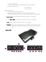
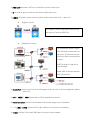
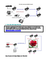
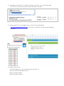
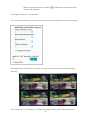
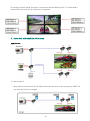
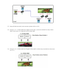
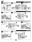
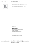
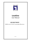
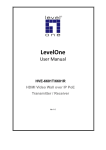
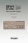
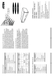
Matrix & Daisy Chain HDMI Extender over CAT.5e/6 & Fiber Optic User’s Manual 1. Introduction Thanks for purchasing the Smart Matrix & Daisy Chainable HDMI Extender over CAT.5e/6 & Optical Fiber. Please read this manual and retain for future reference. 1.1 Features Only one CAT5e/6 & Fiber Optic cable required Adoptive visually lossless compression algorithm HDMI Digital Audio/Video extended distance up to 100 meters (330 feet) between Transmitter and Receiver (point-to-point); up to 30 kilometers between Transmitter and Receiver over Fiber Optic cabling (based on the quality of Fiber Optic and Transceiver modules). Supports Full HD video 1080P Deep Color and PC resolution 1920x1200@60Hz signals, over CAT.5e/6 cabling Smart supporting Crosspoint & Daisy Chain connection for both Transmitter and Receiver units. Mapping different TX source, even some grouping loop for each receiver by LINK ID. Video wall function supported, easily configurable through web UI Built-in Ethernet switch, cost-effective with high flexibility for expansion Wall-mount housing design for easy and robust installation Automatic Display Mode Detection Supports both Interlaced and Progressive Display Modes Supports DDC/DDC2B, Hot-Plug Detection (HPD) and HDCP compliant functions Supports Default EDID and EDID copy function for optimal PC-to-Screen performance Infrared Remote (IR) signal control communication Supports Serial (RS-232) bi-directional 1.2 Package Contents 1. 2. 3. 4. 5. HDMI Extender Transmitter (TX) x 1 HDMI Extender Receiver (RX) x 1 Power Supply DC 5V / 2A (TX & RX pair units) or optional 1 (single unit) IR cables (IR blaster cable x 1; IR receiver cable x 1) User’s Manual x 1 2. Specifications Transmitter HDMI (Female) Receiver Console HDMI Output HDMI (Female) Connectors RS-232 Control Port RJ-45 RJ-45 PC Connectors HDMI Input HDMI (Female) N/A Extension Port RJ-45 Full HD Video 1080p @30Hz / Audio Extension + IR + RS-232 RJ-45 3 (Line In or Line Out) 3 (Line In or Line Out) Fiber Link 1 1 Daisy Chainable Up to 10 layers Up to 10 layers Audio Supports High Definition Audio (HD) 5.1/6.1/7.1 Surround Sound Infrared Remote (IR) Unidirectional Local LED Indicators Remote Power Red LED Link Green LED Power Red LED Link Green LED DDC Supported DDC, DDC2, DDC2B Extension Cable Type & Length CAT.5e / CAT.6 Extending Length: 100m Max. Video Resolution 1920x1200@60Hz, Full HD 1080p@30Hz Wide Screen Supported Yes OS Compatibility OS Independent Power Supply External DC 5V / 2A Power Supply Dimension ( L x W x H ) 155 x 90 x 28.5 mm Weight 430g Housing material Metal Operating Temperature 32 - 122 F ( 0 - 50 C ) Humidity 0% - 80% RH 425g 3. Layout and Descriptions Transmitter (TX): Front Back 1. HDMI IN: Connect a Hi-Definition AV source to this port. 2. HDMI OUT: Connect a HDTV or Hi-Definition monitor to this port. (HDMI loopback) 3. IR: IR blaster port, connect the IR blaster cable to this port. 4. LINK ID: ID selector, select AV Source (Max. 16 AV sources with ID 0 – F per unit). 5. RS-232 Port: Connect a RS-232 to RJ-45 adapter (optional) to this port. Note: The adapter could be made by user and the pin assignments are indicated on the above diagram. 6. RDY (Ready), 7. RESET, 8. PWR: Please refer to the following instructions. Red and Green LED State for Power up: Red LED turns blinking and Green LED is dark → system no setup Red LED turns bright and Green LED is blinking → system setup, but AV source or LINE is disconnected Red and Green LED turn bright → the TX and RX units are communicating correctly. Reset Button State for system function selection Button State Short Press (Red and Green LED to dark) Long Press (Press until Red LED dark off and Green LED lighted) TX (Host side) System to reset Use TX HDMI Loopback port EDID in AV group (Loopback EDID adopted) RX (Client side) System to reset Use RX HDMI output port EDID in AV group (Update EDID) Long Press (Press until Red and Engineering Mode and Reset to Engineering Mode and Reset to Green LED to bright) default default Descriptions: █ Use TX HDMI Loopback port EDID in AV group: This feature is for the client side "Update EDID". █ Use RX HDMI output port EDID in AV group: "Use Loopback EDID" & "Update EDID" feature is used for Multicast Mode to select which monitor/TV EDID is used for system wide EDID usage. For multicast setup, the monitor/TV may be with lower resolution. For example, one monitor/TV with 720p resolution is receiving 1080p video; please select the monitor/TV with the lowest resolution to ensure all the monitors can be displayed correctly. For customer using 1 pair of Host/Client with Multicast mode, the end-user must update EDID correctly. If not, it will cause compatibility issue. ● Operation: Once the button event is triggered correctly at the client side, the system will be setup correctly for Multicast. The selected EDID will be updated to Host Side EEPROM The same operation applies for Loopback EDID. In the system setup, the last EDID updated will stay in the EEPROM. If this button is setup many times, the last one will be applied. █ Engineering Mode: 1. Static IP: 192.168.0.88 2. User can connect to http://192.168.0.88 webpage for firmware update. 3. Firmware update file name: Host : webfwh.bin Client : webfwc.bin █ Reset to Default: 1. Reset any changes in SPI flash setup flag. 2. Re-generate Random MAC address to avoid any possible MAC collision. After Reset to Default and reboot cycle, a new random MAC address will be generated. 9. Power Connector: Connect the included 5V DC power supply to this receptacle. 10. – 12. LINE1 – LINE3: Connect TX’s or RX’s LINE port to this port for AV packets. 13. FIBER: Connect TX’s or RX’s FIBER port to this port for AV packets. 14. FIBER LINK: This LED will turn bright green once the TX and RX units are ready. LED will turn blinking when the data is being transmitted between two units via fiber optic cable. Receiver (RX): Front Back 1. HDMI OUT: Connect a HDTV or Hi-Definition monitor to this port. 2. IR: IR receiver port, connect the IR receiver cable to this port. 3. LINK ID: ID selector, select AV source (Max. 16 AV sources with ID 0 – F per unit). Single AV source: The same ID For single AV source, adjust RX’s LINK ID to be the same as TX’s then RESET RX. Multiple AV sources: For multiple AV sources, adjust each RX’s LINK ID to be same as the one of TX connected to the AV source which you would like to enjoy. RESET RX after its LINK ID has been changed. Please refer to the left example with 3 AV sources. 4. RS-232 Port: Connect a RS-232 to RJ-45 adapter to this port, for RJ-45 pin assignment, please refer to TX. 5. RDY, 6. RESET, 7. PWR: Please refer to TX for detailed instructions. 8. Power Connector: Connect the included 5V DC power supply to this receptacle. 9. – 11. LINE1 – LINE 3: Connect TX’s or RX’s LINE port to this port for AV packets. 12. FIBER: Connect TX’s or RX’s FIBER port to this port for AV packets. 13. FIBER LINK: This LED will turn bright green once the TX and RX units are communicating correctly via fiber optic cable. IR and RS-232 Connection Diagram IR connection Connect the IR blaster cable to the TX’s IR connector. Connect the IR receiver cable to the RX’s IR connector. Put the remote control pointed to the IR receiver eye. Put the IR Transmitter Blaster eye pointed to the IR sensor of the AV source which is intended to be controlled by the remote control. Note: The IR works only when the data is being transmitted between TX and RX. Connect the IR receiver cable to RX Connect the IR blaster cable to TX RS-232 connection 7 Connect the device (e.g. PC, projector…etc) to the RS-232 port of RX by a RS-232 to RJ-45 adatper. Connect the control system to the RS-232 port of TX by a RS-232 to RJ-45 adapter. Operating the control system. The RS-232 connection is bi-directional, the device and the control system are interchangeable and Control System is able to control the device at TX or RX. 4. Video Wall with Single AV Source 8 Video Wall is supported by the free software called Bonjour. Make sure the control PC has been installed the Bonjour SDK, If the control PC (Windows OS) doesn’t install Bonjour SDK yet, please install it. Google “bonjour SDK download” for the installation file or download it here: http://developer.apple.com/opensource/ Setup Procedures for Single AV Source 2 x 2 Video Wall 4.1. Configure the control PC ‘s IP address setting to 169. 254. xxx. xxx with Net Mask 255.255.0.0, xxx means arbitrary number between 0 and 999. 4.2. Open control PC’s IE or Google Chrome. Link to TX by web address http://ast-gateway0000.local/vw/ , if the link is successful, you will see the following web page: 9 4.3. System setup for TX: Follow the below (1) to (7) steps for System setup for TX. Step (1): Choose and double click TX Step (2): Choose System Step (3): Choose Utilities: Step (4): Console API Command: key in astparam s multicast_on y, then click Apply. 10 Step (5): Console API Command: key in astparam s en_video_wall y, then click Apply. Step (6): Console API Command: key in astparam save, then click Apply. Step (7): Console API Command: key in reboot, then click Apply. The System setup for TX is finished after reboot. 4.4. System setup for RX: 11 Choose and double click RX1 and repeat the above steps from step (2) to step (7), then RX2, RX3, and RX4. System setup for RX is completed after all the 4 units RX have been setup by the above steps from step (2) to step (7). 4.5. Video Wall Setup 4.5.1. Basic Setup: Bezel and Gap Compensation OW: Outside Width OH: Outside Height VW: Viewable Width VH: Viewable Height OW, OH, VW, VH must be integer Below is the example about OW and VW: The OH and VH could be obtained by the same method. Or keep the default value 0 of OW, OH, VW, VH to skip the adjustments. 4.5.2. Basic Setup: Wall Size and Position Layout 12 Vertical Monitor Count: Number of Monitors in Row (e.g. : for 3 x 2 Video Wall, the Vertical Monitor Count is 3) Horizontal Monitor Count: Number of Monitors in Column (e.g. : for 3 x 2 Video Wall, the Horizontal Monitor Count is 2) Row Position: Monitor’s Row Position in Video Wall, begins from 0 Column Position: Monitor’s Column Position in Video Wall, begins from 0 Below is the example for 2 x 2 Video Wall with each Monitor’s Row Position and Column Position by ( Row Position, Column Position ) Single Host Mode: Enable ( ) if the AV source is single Apply To: Apply the settings to the chosen device(s) in the list Show OSD: The RX’s OSD number (e.g. 13 ) appears on the corresponding Monitor when Show OSD is enabled ( number will disappear. ). Disable Show OSD and the OSD 4.6. Single AV Source 2 x 2 Video Wall 4.6.1. Setup all 4 Monitors with the same content by the settings shown on the below figure. Press Apply then the 4 Monitors are with the same content, please refer to the following example: 4.6.2. Setup the ( 0, 0 ) Monitor, i.e. Monitor with Row Position 0 and Column Position 0. 14 Vertical Monitor Count: Choose “2” Horizontal Monitor Count: Choose “2” Row Position: Choose “0” Column Position: Choose “0” Enable Single Host Mode Apply To: Choose “0” ( OSD number 0 ) Then the first component of 2 x 2 Video Wall on ( 0, 0 ) Monitor is obtained. 4.6.3. Setup the ( 0, 1 ) Monitor, i.e. Monitor with Row Position 0 and Column Position 1. Vertical Monitor Count: Choose “2” Horizontal Monitor Count: Choose “2” Row Position: Choose “0” Column Position: Choose “1” Enable Single Host Mode Apply To: Choose “2” ( OSD number 2 ) Then the 2nd component of 2 x 2 Video Wall on ( 0, 1 ) Monitor is obtained. 15 By using the same method, the other 2 components will be obtained. The 2 x 2 Video Wall is present after the setup for all 4 Monitors is completed. 5. Video Wall with Multiple AV Sources 2 AV Sources: 5.1. Setup LINK ID Setup LINK ID such that the TX’s and RX’s LINK ID are the same in the same group. RESET the unit after the LINK ID is changed. 16 5.2. Setup all Monitors with same content: please refer to 4.6.1. 5.3. Group 1 is 1 x 2 Video Wall with single AV Source # 1, and the methods for setup Video Wall is the same as in Single AV Source Video Wall. 5.4. Group 2 is 1 x 2 Video Wall with Single AV Source #2 and the setup methods are the same as in 5.3.