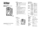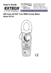
1
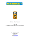
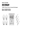
Safety
Specifications
International Safety Symbols
USER'S MANUAL
This symbol, adjacent to another symbol or terminal, indicates the user
must refer to the manual for further information.
This symbol, adjacent to a terminal, indicates that, under normal use,
hazardous voltages may be present.
Multimeter
Auto ranging Pocket DMM
DMR-602
Double insulation
This meter has been designed for safe use, but must be operated with caution. The
rules listed below must be carefully followed for safe operation.
Maximum Input
V DC or V AC
600V DC/AC
µA AC/DC
200mA/500V (fast acting resettable fuse)
Resistance, Diode &
Continuity Test
600V DC/AC
3.
• 3-3/4 digit 4000 count LCD display
• Built-in non-contact AC voltage detector
• Flashlight
• Double Molded housing
• CATIV 600V
4.
5.
6.
7.
Resistance
Range & Resolution
±(0.8% rdg + 2digits)
4.000V, 40.00V
±(1.0% rdg + 5digits)
400.0V, 600V
400.0V, 600V
400.0µA, 4000µA
40.00mA, 200.0mA
400.0µA, 4000µA
40.00mA, 200.0mA
±(1.0% rdg + 2digits)
±(1.5% rdg + 5digits)
±(2.0% rdg + 2digits)
±(2.5% rdg + 5digits)
400.0Ω
±(0.8% rdg + 5digits)
40.00kΩ, 400.0kΩ
±(0.8% rdg + 2digits)
4.000kΩ,
4.000MΩ
40.00MΩ
4.000nF
Capacitance
Accuracy
400mV, 4.000V,40.00V
40.00nF
400.0nF, 4.000µF
40.00µF, 200.0µF
±(1.2% rdg + 5digits)
±(0.3% rdg + 5digits)
±(5.0% rdg + 5digits)
±(5.0% rdg + 0.6nF)
±(3.5% rdg + 30digits)
±(3.0% rdg + 20digits)
±(5.0% rdg + 30digits)
Frequency
9.999Hz, 99.999Hz, 999.9Hz,
9.999kHz,
±(1.0% rdg + 2digits)
Duty Cycle
0.5-99%
±(2.0% rdg + 5digits)
SE EXTREME CAUTION when working with voltages greater than 25VAC
U
rms or 35VDC. These voltages are considered a shock hazard.
Note: Accuracy specifications consist of two elements:
• (% reading) This is the accuracy of the measurement circuit
• (+ digits) This is the accuracy of the analog to digital converter
Accuracy is stated at 65ºF to 83ºF (18ºC to 28ºC) < 75% RH
LWAYS discharge capacitors and remove power from the device under test
A
before performing Diode, Resistance or Continuity tests.
Non-Contact Voltage
O NOT measure voltage if the voltage on the “COM” input jack exceeds 600V
D
above earth ground.
EVER connect the meter leads across a voltage source when the function
N
switch is in the current, resistance or diode mode.
LWAYS turn off the meter and disconnect the test leads from the circuit before
A
opening the cover to replace battery.
ONLY operate the meter with the battery cover fastened securely.
• 200mA/500V Resettable Fused current inputs and
Diode Test
Continuity Check
Display
Polarity
Input Impedance
Meter Description
AC Response
1.
Non-contact AC voltage detector probe tip
Auto Power Off
2.
Non-contact AC voltage indicator light
3.
3 3/4 Digit (4000 count)
4.
MODE button
5.
Function switch
6.
Flashlight
7.
Flashlight button
8.
Hz/%Duty Cycle button
9.
Battery Cover
10. Test leads
100 to 600VAC; 50/60Hz
Test current 1mA, open circuit voltage of 1.5V DC typical
Audible signal if the resistance is <100Ω
4000 count 3-3/4 digit LCD
Over range indication “OL” is displayed
Low Battery Indication
• Overload protection on all ranges
• Autoranging with auto power off
DC Current
Do not exceed the maximum rated input limits.
Function
2.
Features
AC Voltage
50-60Hz
AC Current
50-60Hz
Input Limits
www.circuittest.com
DC Voltage
Safety Precautions
1.
CIRCUIT-TEST ELECTRONICS
Function
ACV Bandwidth
Fuse
Batteries
Automatic; (-) sign for negative polarity.
symbol indicates low battery condition.
>7.5MΩ (VDC & VAC)
Average responding
50Hz to 60Hz
15 minutes (approximately)
mA, µA ranges; 0.2A/500V fast acting (resettable fuse)
Two 1.5V AAA
Operating Temperature 32ºF to 104ºF (0ºC to 40ºC)
Storage Temperature
Weight Size
Safety / Approvals
14ºF to 122ºF (-10ºC to 50ºC)
0.319 lb (145g)
104x55x32.5mm (4.09”x2.1”x1.2”)
This meter is UL and CUL approved and conforms to IEC61010-1 for Overvoltage Category CAT IV 600V.
Operating Instructions
WARNING: Risk of electrocution. High-voltage circuits, both AC and DC, are very
dangerous and should be measured with great care.
3.
Touch the test probe tips to the circuit or wire you wish to check.
4.
If the resistance is less than approximately 100Ω, the audible signal will sound.
If the circuit is open, the display will indicate “OL”.
LWAYS turn the function switch to the OFF position when the meter is not in
A
use. This meter automatically shuts OFF after 15 minutes of inactivity.
DIODE TEST
2.
If “OL” appears in the display during a measurement, the value exceeds the
range you have selected. Change to a higher range.
1.
Set the function switch to the Ω
2.
Press the MODE button to indicate
3.
Touch the test probes to the diode under test. Forward voltage will typically
indicate 0.400 to 0.700V. Reverse voltage will indicate “OL”. Shorted devices
will indicate near 0V and an open device will indicate “OL” in both polarities
AC/DC VOLTAGE MEASUREMENTS
CAUTION: Do not measure AC/ DC voltages if a motor on the circuit is being
switched ON or OFF. Large voltage surges may occur that can damage the meter.
1.
Set the function switch to the
position.
2.
Press the MODE button to indicate “DC” or “AC” on the display.
3.
ouch the black test probe tip to the negative side of the circuit. Touch the red
T
test probe tip to the positive side of the circuit.
4.
Read the voltage in the display.
For current measurements up to 4000μA C/DC, set the function switch to the
position.
2.
position.
on the display
CAPACITANCE MEASUREMENTS
WARNING: To avoid electric shock, disconnect power to the unit under test and
discharge all capacitors before taking any capacitance measurements. Remove
the batteries and unplug the line cords.
1.
Set the function switch to the Ω
2.
Press the MODE button to indicate nF on the display.
3.
Touch the test leads to the capacitor to be tested.
4.
Read the capacitance value on the display.
position.
For current measurements up to 200mA AC/DC, set the function switch to the
position.
Set the function switch to the
2.
Press the Hz/% button to display Hz on the display.
3.
Touch the test probe tips to the circuit under test.
4.
Read the frequency on the display.
5.
Press the Hz/% button again to display % on the display.
Press the MODE button to indicate “AC” or “DC” on the display.
6.
Touch the test probe tips to the circuit under test.
4.
emove power from the circuit under test, then open up the circuit at the point
R
where you wish to measure current.
7.
Read the % duty cycle on the display.
5.
ouch the black test probe tip to the negative side of the circuit. Touch the red
T
test probe tip to the positive side of the circuit.
NON-CONTACT AC VOLTAGE MEASUREMENT
6.
Apply power to the circuit and read the current in the display.
RESISTANCE MEASUREMENTS
WARNING: To avoid electric shock, disconnect power to the unit under test and
discharge all capacitors before taking any resistance measurements. Remove the
batteries and unplug the line cords.
1.
Set the function switch to the Ω
2.
Press the MODE button to indicate Ω on the display.
3.
ouch the test probe tips across the circuit or part under test. It is best to disT
connect one side of the part under test so the rest of the circuit will not interfere
with the resistance reading.
4.
Read the resistance in the display.
position.
WARNING: To avoid electric shock, never measure continuity on circuits or wires
that have voltage on them.
Set the function switch to the Ω
Press the MODE button to indicate
2.
Turn off the meter.
3.
Remove the screw securing the battery cover at the bottom of the meter.
4.
Replace the batteries observing the correct polarity.
5.
Replace the cover and secure the screw.
WARNING: To avoid electric shock, do not operate your meter until the battery
cover is in place and fastened securely.
RESETTABLE FUSE
The resettable fuse (200mA/500V) will open if the current limits of the meter are
exceeded and the fuse will automatically reset itself when the suspected current is
removed from the meter’s input.
LIMITED WARRANTY
Circuit-Test Electronics warrants to the original purchaser that this product be free of
defect in material or workmanship for a period of 2 years from the date of purchase.
Any product which has been subjected to misuse or accidental damage is excluded
from the warranty. Except as stated above, Circuit-Test Electronics makes no promises
or warranties either expressed or implied including warranties of merchantability or the
fitness for any particular purpose.
WARNING: Risk of electrocution. Before use, always test the Voltage Detector on
a known live circuit to verify proper operation.
The Voltage Detector works with the function switch in any position including OFF.
1.
ring the probe tip next to the hot conductor or insert into the hot side of the
B
electrical outlet.
2.
If AC voltage is present, the detector light will illuminate.
NOTE: NOTE: The conductors in electrical cord sets are often twisted. For best results,
rub the probe tip along a length of the cord to assure placing the tip in
close proximity to the live conductor.
The detector is designed with high sensitivity. Static electricity or other
sources of energy may randomly trip the sensor. This is normal operation
FLASHLIGHT
CONTINUITY CHECK
2.
will appear in the display when the battery drops below the operating voltage
and requires replacing. /HZ/% position.
1.
3.
1.
1.
FREQUENCY/DUTY CYCLE MEASUREMENTS
AC/DC CURRENT MEASUREMENTS
1.
REPLACING THE BATTERY
WARNING: To avoid electric shock, disconnect the test leads from any source of
voltage before removing the battery door.
1.
NOTE: On some low AC and DC voltage ranges, with the test leads not connected to a
device, the display may show a random, changing reading. This is normal and is caused
by the high-input sensitivity. The reading will stabilize and give a proper measurement
when connected to a circuit.
Maintenance
position.
on the display
Press and hold the
flashlight off.
button to turn the flashlight on. Release the button to turn the
AUTO POWER OFF
The auto off feature will turn the meter off after 15 minutes.
M-DMR-602 / 07R13