1
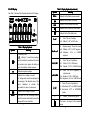
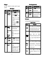
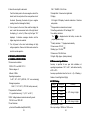
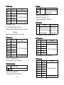
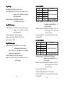
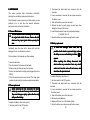
HANDHELD
DIGITAL MULTIMETER
MS8268
OPERATOR
OPERATOR’’S INSTRUCTION
MANUAL
Table of Contents
Table of Contents
TITLE
PAGE
1. GENERAL INSTRUCTIONS
1.1 Precaution safety measures
1.1.1 Preliminary
1.1.2 During use
1.1.3 Symbols
1.1.4 Instructions
1.2 Safety mechanisms
1
1
1
2
4
4
5
2. DESCRIPTION
6
2.1 Instrument Familiarization
2.2 LCD Display
2.3 Keypad
2.4 Terminals
6
7
9
10
2.5 Rotary switch
2.6 Accessories
11
11
3. FUNCTION DESCRIPTION
12
3.1 General Functions
3.1.1 Misconnection alarm system
3.1.2 DATA HOLD mode
3.1.3 Manual ranging and Autorange mode
3.1.4 Battery Saver
3.1.5 Relative measurement mode
3.2 Measurement Functions
3.2.1 AC and DC Voltage measurement
12
12
13
13
14
14
15
15
Ⅰ
TITLE
PAGE
3.2.2 Resistance measurement
16
3.2.3 Diode Test
17
3.2.4 Continuity Check
18
3.2.5 Transistor measurement
18
3.2.6 Capacitance measurement
19
3.2.7 Frequency and Duty Cycle measurement
20
3.2.8 Current measurement
22
4. TECHNICAL SPECIFICATIONS
23
4.1 GENERAL SPECIFICATIONS
4.2 Measurement specifications
4.2.1 DC Voltage
4.2.2 AC Voltage
4.2.3 Resistance
4.2.4 Audible continuity
4.2.5 Diode
4.2.6 Transistor
4.2.7 Capacitance
4.2.8 Frequency
4.2.9 DC CURRENT
4.2.10 AC CURRENT
23
24
24
25
25
25
26
26
26
26
28
28
5. MAINTENANCE
29
5.1 General Maintenance
5.2 Fuse replacement
5.3 Battery replacement
29
29
30
Ⅱ
1. GENERAL INSTRUCTIONS
This instrument complies with IEC 1010-1 (61010-1@IEC:
2001), CAT. II 1000V and CAT. III 600V overvoltage standards.
See Specifications.
To get the best service from this instrument, read carefully this
user's manual and respect the detailed safety precautions.
International symbols used on the Meter and in this manual
are explained in chapter 1.1.3
1.1 Precautions safety measures
1.1.1 Preliminary
* Measurement category III is for measurements performed in
the building installation.
NOTE: Examples are measurements on distribution boards,
circuit-breakers, wiring, including cables, bus-bars, junction
boxes, switches, socket-outlets in the fixed installation, and
equipment for industrial use and some other equipment, for
example, stationary motors with permanent connection to
the fixed installation.
* Measurement category II is for measurements performed on
circuits directly connected to the low voltage installation.
NOTE: Examples are measurements on household
appliances, portable tools and similar equipment.
* Measurement category I is for measurements performed on
circuits not directly connected to MAINS.
NOTE: Examples are measurements on circuits not derived
from MAINS, and specially protected (internal) MAINS
derived circuits. In the latter case, transient stresses are
variable; for that reason, requires that the transient
withstand capability of the equipment is made known to the
user.
1
* When using this Multimeter, the user must observe all
normal safety rules concerning:
― Protection against the dangers of electric current.
― Protection of the Multimeter against misuse.
* For your own safety, only use the test probes supplied with
the instrument. Before use, Check that they are in good
condition.
1.1.2 During use
* If the meter is used near noise generating equipment, be
aware that display may become unstable or indicate large
errors.
* Do not use the meter or test leads if they look damaged.
* Use the meter only as specified in this manual; otherwise,
the protection provided by the meter may be impaired.
* Use extreme caution when working around bare conductors
or bus bars.
* Do not operate the meter around explosive gas, vapor, or dust.
* Verify a Meter's operation by measuring a known voltage.
Do not use the Meter if it operates abnormally. Protection
may be impaired. When in doubt, have the Meter serviced.
* Uses the proper terminals, function, and range for your
measurements.
* When the range of the value to be measured is unknown,
check that the range initially set on the multimeter is the
highest possible or, wherever possible, choose the
autoranging mode.
* To avoid damages to the instrument, do not exceed the
maximum limits of the input values shown in the technical
specification tables.
* When the multimeter is linked to measurement circuits, do
not touch unused terminals.
2
* Do not apply any voltage measurement between the 10A
* Replace the batteries as soon as the battery indicator (
terminal and the COM terminal.
* Caution when working with voltages above 60Vdc or 30Vac
rms. Such voltages pose a shock hazard.
* When using the probes, keep your fingers behind the finger
guards.
* When making connections, connect the common test lead
before connecting the live test lead; when disconnecting,
disconnect the live test lead before disconnecting the
common test lead.
* Before changing functions, disconnect the test leads from
the circuit under test.
* For all dc functions, including manual or auto-ranging, to
avoid the risk of shock due to possible improper reading,
verify the presence of any ac voltages by first using the ac
function. Then select a dc voltage range equal to or greater
than the ac range.
* Disconnect circuits power and discharge all high-voltage
capacitors before testing resistance, continuity, diodes, or
capacitance.
* Before measuring current, check the meter's fuse and turn
off power to the circuit before connecting the meter to the
circuit.
* Never perform resistance or continuity measurements on
live circuits.
* In TV repair work, or when carrying out measurements on
power switching circuits, remember that high amplitude
voltage pulses at the test points can damage the multimeter.
Use of a TV filter will attenuate any such pulses.
* Use three 1.5V AAA batteries, properly installed in the
Meter's battery case, to power the Meter.
3
) appears. With a low battery, the Meter might
produce false readings that can lead to electric shock and
personal injury.
* Do not measure voltages above 600V in Category III, or
1000V in Category II installations.
1.1.3 Symbols:
Symbols used in this manual and on the instrument:
Caution:
refer
to
the
instruction
manual.
Incorrect use may result in damage to the device
or its components.
Dangerous voltage may be present.
~
AC (Alternating Current)
DC (Direct Current)
AC or DC
Earth ground
Double insulated
Fuse
Conforms to European Union directives
1.1.4 Instructions
* Remove test leads from the Meter before opening the Meter
case or battery cover.
* When servicing the Meter, use only specified replacement
parts.
* Before opening up the instrument, always disconnect from
all sources of electric current and make sure you are not
charged with static electricity, which may destroy internal
components.
4
* Any adjustment, maintenance or repair work carried out on
the meter while it is live should be carried out only by
2. DESCRIPTION
2.1 Instrument Familiarization
appropriately qualified personnel, after having taken into
account the instructions in this present manual.
* A "qualified person" is someone who is familiar with the
installation, construction and operation of the equipment
and the hazards involved. He is trained and authorized to
energize and de-energize circuits and equipment in
accordance with established practices.
AC
* When the instrument is opened up, remember that some
internal capacitors can retain a dangerous potential even
after the instrument is switched off.
* If any faults or abnormalities are observed, take the
instrument out of service and ensure that it cannot be used
until it has been checked out.
* If the meter is not going to be used for a long time, take out
the battery and do not store the meter in high temperature or
high humidity environment.
1.2 Safety mechanisms
* Misconnection alarm system
* If the maximum range is repeatedly exceeded, a continuous
audible signal warns the user in DCV, ACV, DCµA, ACµA,
DC mA, AC mA, DC 10A and AC 10A functions.
1. LCD display
5
2. Keypad
3. Rotary switch
6
4. Terminals
2.2 LCD Display
See Table 1 indicated for information about the LCD display.
Symbol
Table 1. Display Symbols (continued
continued))
Meaning
∆
REL
REL∆
Indicator for the Relative measurement.
Indicator for the Diode Test mode
hFE
Indicator for the transistor test mode
Indicator for the Continuity Check mode.
Indicator for the Data Hold mode
AC
V, mV
Meaning
The battery is low.
Warning: To avoid false readings,
which could lead to possible electric shock
or personal injury, replace the battery as
soon as the battery indicator appears.
A, mA, µA
Ω, k Ω, MΩ
Ω:
Ohm. The unit of resistance.
kΩ: Kilohm. 1x10³ or 1000 ohms.
MΩ: Megohm. 1x10⁶ or 1,000,000 ohms.
Hz:
Hz, kHz, MHz
Hertz. The unit of frequency in
cycles/second.
KHz: Kilohertz. 1x10³ or 1000 hertz.
MHz: Megahertz. 1x10⁶ or 1,000,000 hertz.
µF, nF
F: Farad. The unit of capacitance.
µF: Microfarad.1x10-6 or 0.000001 farads.
nF: Nanofarad. 1x10⁻⁹ or 0.000000001
farads.
Indicates negative readings.
Indicator for ac voltage or current.
AC voltage and current are displayed as
the average of the absolute value of the
input, calibrated to indicate the
equivalent rms value of a sine wave.
Indicator for dc voltage or current.
AUTO
The Meter is in the Autorange mode in
which the meter automatically selects the
range with the best resolution.
7
Volts. The unit of voltage.
Millivolt. 1x10⁻³ or 0.001 volts.
A: Amperes (amps). The unit of current.
mA: Milliamp. 1x10⁻³ or 0.001 amperes.
µA:: Microamp. 1x10⁻⁶ or 0.000001
amperes
Table 1. Display Symbols
Symbol
V:
mV:
%
%:
Percent. The unit of Duty cycle.
The input is too large for the selected
range.
8
2.3 Keypad
See Table 2 indicated for information about the keypad
operations.
Table 2. Keypad
Key
RANGE
Function
V~
V~,,V
, Ω ,
mA and µA
SELECT
V~
V~,, A,
and µA.
HOLD
Any switch
Press HOLD to enter and exit
position
1. Press RANGE to enter the
manual ranging mode.
2. Press RANGE to step
through
the
ranges
available for the selected
function.
3. Press and hold RANGE for
2 seconds to return to
autoranging.
LIGHT
mA
Press to turn the backlight on.
The backlight will be auto-off
about 5 seconds later.
Table 4. Terminals
Terminal
Description
Return
COM
terminal
for
all
measurements.
(Receiving the black test lead or the “com”
plug of the special multi-function socket)
Input for voltage, resistance, capacitance,
frequency,
Press REL to enter and exit
the Relative measurement
mode.
9
Any switch
position
See Table 4 indicated for information about the terminals.
Switches between dc and ac
current.
1 Press to start the frequency
counter.
2 Press again to enter duty
cycle (duty factor) mode.
3 Press again to exit the
frequency counter mode.
the Data Hold mode.
4 Terminals
2.
2.4
VΩHz
Any switch
position
Hz
Hz// %
Operation performed
Disables automatic power-off
feature.
Power-up
Option
REL
Function
Operation performed
Switches between Diode Test
and Continuity check.
A, mA and
µA
Table 2. Keypad
Keypad((continued
continued))
Key
diode
and
continuity
measurements. (Receiving the red test lead
or the “+” plug of the special multi-function
socket).
Input for hFE and 0.001mA to 400mA
hFE µA
current measurements. (Receiving the red
mA
test lead or the “+” plug of the special
multi-function socket)
A
10
10A
Input
for
400mA to
10A current
measurements. (Receiving the red test
lead).
10
2.5 Rotary switch
A eleven-position rotary selector switch gives access to
the following quantities:
ℕ Current: 10A
ℕ Current: mA
ℕ Current: µA
ℕ DC Voltage
ℕ AC Voltage
ℕ OFF: off position
ℕ Resistance
ℕ Diode and Continuity (with beep)
ℕ Capacitance
ℕ Transistor: hFE
ℕ Frequency
3. FUNCTION DESCRIPTION
3.1 General Functions
3.1.1 Misconnection alarm system
The input terminals of the meter are equipped with sound and
light alarms against misconnection of test leads.
At V, Ω,,
and
ranges:
1 The red lights at the “V” and “COM” terminals will be off
after the test leads are plugged in.
2 The buzzer will sound upon misconnection of the test
leads in the “mA” or “10A” terminals to warn the user.
At the same time, the lights at the “V” and “COM”
terminals will flash to remind the user to plug in the test
leads there.
At μA, mA
mA,, and hFE ranges
ranges:
2.6 Accessories
1 The red lights at the “mA” and “COM” terminals will be off
Delivered with the multimeter:
ℕ User's manual
after the test leads are plugged in.
2 The buzzer will sound upon misconnection of the test
ℕ Test leads
ℕ Special Multi-function socket
leads in the “V” or “10A” terminals to warn the user.
At
the same time, the red lights at the “mA” and “COM”
terminals will flash to remind the user to plug in the test
leads there.
At A range
range:
1 The red lights at the “10A” and “COM” terminals will be
off after the test leads are plugged in.
2 The buzzer will sound upon misconnection of the test
leads in the “V” or “mA” terminals to warn the user.
At the same time, the lights at the “10A” and “COM”
terminals will flash to remind the user to plug in the test
leads there.
11
12
2 DATA HOLD mode
3.1.
3.1.2
Data Hold mode makes the meter stop updating the
display. Enabling Data Hold function in autorange mode
makes the meter switch to Manual ranging mode, but the
full-scale range remains the same. Data Hold function
can be cancelled by changing the measurement mode,
pressing RANGE key, or push HOLD key again.
To enter and exit the Data Hold mode:
1. Press HOLD key (short press). Fixes the display on
H” is displayed.
the current value, “H
2. A second short press returns the meter to normal
mode.
3 Manual ranging and Autorange mode
3.1.
3.1.3
The Meter has both manual ranging and autorange
options.
* In the autorange mode, the Meter selects the best
range for the input detected. This allows you to switch
test points without having to reset the range.
* In the manual ranging mode, you select the range. This
allows you to override autorange and lock the meter in
a specific range.
* The Meter defaults to the autorange mode in
measurement functions that have more than one range.
When the Meter is in the autorange mode, AUTO is
displayed.
To enter and exit the manual range mode:
1. Press RANGE key. The Meter enters the manual
ranging mode. AUTO turns off. Each presses of
RANGE key increments the range. When the highest
range is reached, the Meter wraps to the lowest
range.
13
NOTE: If you manually change the measurement range
after entering the Data Hold modes, the Meter exits this
mode.
2. To exit the manual ranging mode, press and hold down
RANGE key for two seconds. The Meter returns to
the autorange mode and AUTO is displayed.
4 Battery Saver
3.1.
3.1.4
The Meter enters the "sleep mode" and blanks the display
if the Meter is on but not used for 15 minutes.
Press the HOLD key or rotate the rotary switch to wake
the meter up.
To disable the Sleep mode, hold down the SELECT key
while turning the meter on.
One minute before power off, the beeper will sound 5
sounds. The beeper will sound again before power off.
5 Relative measurement mode
3.1.
3.1.5
The Meter will display relative measurement in all
functions except frequency.
To enter and exit the relative measurement mode:
1. With the Meter in the desired function, touch the test
leads to the circuit on which you want future
measurement to be based.
2. Press REL key to store the measured value and
activate the relative measurement mode. The
difference
between
the
reference
value
and
subsequent reading is displayed.
3. Press REL key for more than 2 seconds to return the
Meter to normal operation.
14
3.2 Measurement Functions
3.2.1 AC and DC Voltage measurement
To avoid electrical shock and/or damage to the
instrument, do not attempt to take any voltage
measurement that might exceed 1000Vdc or
750Vac rms.
To avoid electrical shock and/or damage to the
instrument, do not apply more than 1000Vdc or
750Vac rms between the common terminal and
the earth ground.
The polarity of ac (alternating current) voltage varies over
time; the polarity of dc (direct current) voltage is constant.
ℕ For better accuracy when measuring the dc offset of an
ac voltage, measure the ac voltage first. Note the ac
voltage range, then manually select a dc voltage range
equal to or higher than the ac range. This improves the
accuracy of the dc measurement by ensuring that the
input protection circuits are not activated.
3.2.2 Resistance measurement
To avoid electrical shock and/or damage to the
instrument, disconnect circuit power and
discharge all high-voltage capacitors before
measuring resistance.
The Meter's DC voltage ranges are 400.0mV, 4.000V,
The Meter's resistance ranges are 400.0 Ω , 4.000k Ω ,
40.00V, 400.0V and 1000V; AC voltage ranges are
40.00kΩ, 400.0kΩ, 4.000MΩ and 40.00MΩ.
400.0mV , 4.000V, 40.00V, 400.0V and 750V.
(AC 400.0mV range only exists in manual ranging mode).
To measure resistance:
To measure ac or dc voltage:
1. Set rotary switch to the DCV or ACV range.
2. Connect the black and red test leads to the COM and
V terminals respectively.
1. Set the rotary switch to Ω range.
2. Connect the black and red test leads to the COM and
Ω terminals respectively.
3. Connect the test leads to the circuit being measured
and read the displayed value.
3. Connect the test leads to the circuit being measured
4. Read the displayed value. The polarity of red test lead
connection will be indicated when making a DCV
measurement.
NOTE:
ℕ Unstable display may occur especially at 400mV range,
even though you do not put test leads into input terminals,
in this case, if an erroneous reading is suspected, short
the V terminal and the COM terminal, and make sure the
zero display.
15
Some tips for measuring resistance:
ℕ The measured value of a resistor in a circuit is often
different from the resistor's rated value. This is because
the Meter's test current flows through all possible paths
between the probe tips.
ℕ In order to ensure the best accuracy in measurement of low
resistance, short the test leads before measurement and
memory the test probe resistance in mind. This necessary to
subtract for the resistance of the test leads.
16
ℕ The resistance function can produce enough voltage to
forward-bias silicon diode or transistor junctions, causing
them to conduct. To avoid this, do not use the 40MΩ range
for in-circuit resistance measurements.
ℕ On 40M Ω range, the meter may take a few seconds to
stabilize reading. This is normal for high resistance
5. The meter will show the approx. forward voltage of the
diode.
In a circuit, a good diode should still produce a forward bias
reading of 0.5V to 0.8V; however, the reverse-bias reading
can vary depending on the resistance of other pathways
between the probe tips.
3.2.4 Continuity Check
measuring.
ℕ When the input is not connected, i.e. at open circuit,
the figure "OL" will be displayed for the overrange
condition.
To avoid electrical shock and/or damage to the
instrument, disconnect circuit power and
discharge all high-voltage capacitors before
testing for Continuity.
3.2.3 Diode Test
To avoid electrical shock and/or damage to the
instrument, disconnect circuit power and
discharge all high-voltage capacitors before
testing diodes.
Use the diode test to check diodes, transistors, and other
semiconductor devices. The diode test sends a current
through the semiconductor junction, then measures the
voltage drop across the junction, A good silicon junction
drops between 0.5V and 0.8V.
To test a diode out of a circuit:
1. Set the rotary switch to
range.
2. Press the SELECT key to activate Diode Test.
3. Connect the black and red test leads to the COM and
VΩ terminals respectively.
4. For forward-bias readings on any semiconductor
component, place the red test lead on the
component's anode and place the black test lead on
the component's cathode.
17
To test for continuity:
1. Set the rotary switch to
range.
2. Press the SELECT key to activate Continuity Check.
3. Connect the black and red test leads to the COM and
Ω terminals respectively.
4. Connect the test leads to the resistance in the circuit
being measured.
5. When the test lead to the circuit is below 50 Ω , a
continuous beeping will indicate it.
Note:
ℕ Continuity test is available to check open/short of the
circuit.
3.2.5 Transistor measurement
To avoid electrical shock and/or damage to the
Vdc or
instrument, do not apply more than 250
250Vdc
Vac rms between the hFE terminal and the
250
250Vac
COM terminal.
18
To test the hFE of transistor:
To measure capacitance:
1. Set the rotary switch to hFE range.
1. Set the rotary switch to
2. Connect the “com” plug and “+” plug of the special
2. Connect the black and red test leads to the COM and
multi-function socket to the COM and hFE terminals.
3. Determine whether the transistor to be tested is NPN or
PNP type and locate the Emitter, Base and Collector
leads.
terminals
respectively.
range.
(or
you
can
measure
the
capacitance by using the special Multi-Function Socket)
3. Connect the test leads to the capacitor being measured
and read the displayed value.
4. Insert leads of the transistor into proper holes of the
Some tips for measuring capacitance:
ℕ The meter may take a few seconds (200 µ F range, 30
special multi-function socket.
5. The meter will show the approx. hFE value at test
condition of base current 10μA and Vce 2.8V.
seconds) to stabilize reading. This is normal for high
capacitance measuring.
ℕ To improve the accuracy of measurements less than 4nF,
6 Capacitance measurement
3.2.
3.2.6
subtract the residual capacitance of the Meter and leads.
To avoid electrical shock and/or damage to the
instrument,
disconnect
circuit
power
and
7 Frequency and Duty Cycle measurement
3.2.
3.2.7
discharge all high-voltage capacitors before
Do not measure Frequency on high voltage
measuring capacitance. Use the dc voltage
250
Vdc or 250
Vac rms) to avoid electrical shock
(>
(>250
250Vdc
250Vac
function to confirm that the capacitor is
hazard and/or damage to the instrument.
discharged.
Capacitance is the ability of a component to store an
electrical charge.
The unit of capacitance is the farad (F). Most capacitors are
in the nanofarad to microfarad range. The Meter measures
capacitance by charging the capacitor with a known current
for a known period of time, measuring the resulting voltage,
then calculating the capacitance. The measurement takes
about 1 second per range.
The Meter's capacitance ranges are 4.000nF 40.00nF,
400.0nF, 4.000µF, 40.00µF and 200.0µF.
19
To measure frequency or Duty Cycle:
A) To measure frequency by Hz range
ℕ Set the rotary switch to Hz range.
ℕ Connect the black and red test leads to the COM and
Hz terminals respectively.
ℕ Connect the test leads across the source or load
under measurement, and read the displayed value.
ℕ To make a duty cycle measurement, press the Hz %
key again.
ℕ Read the percent of duty cycle on the display.
20
Note:
Distortion can cause multiple triggering of the frequency
ℕ Reading is possible at input voltages above 3V rms, but the
counter. Selecting a higher voltage range might solve this
accuracy is not guaranteed.
problem by decreasing the sensitivity of the meter. Also, try
ℕ In noisy environment, it is preferable to use shield cable for
measuring small signal.
selecting a dc range, which raises the trigger level. In
general, the lowest frequency displayed is the correct one.
e (or AC Current)
B) To measure frequency by AC Voltag
Voltage
range
ℕ Set the rotary switch to the desired range (AC Voltage or
AC Current).
ℕ Connect the black and red test leads to the COM and V
(or mA
mA) terminals respectively.
ℕ Connect the meter to the signal source; then press Hz/%
key.
ℕ For 5V logic signals (TTL), use the 4Vdc range. For 12V
switching signals in automobiles, use the 40Vdc range.
ℕ Read the frequency of the AC signal on the display.
ℕ To make a duty cycle measurement, press the Hz %
key again.
ℕ Read the percent of duty cycle on the display.
Note:
ℕ If the reading is 0.000Hz or is unstable, the input signal may
be below or near the trigger level.
These problems can frequently be fixed by selecting a lower
range, which increases the sensitivity of the meter. In the
DCV function, the lower ranges also have lower trigger
levels.
ℕ If a reading seems to be a multiple of what you expect, the
input signal may be distorted.
21
8 Current measurement
3.2.
3.2.8
To avoid damage to the Meter or injury if the fuse
blows, never attempt an in-circuit current
measurement where the open-circuit potential to
earth is greater than 250V.
To avoid damage to the meter, check the meter's
fuse before proceeding. Use the proper terminals,
function, and range for your measurement. Never
place the probes in parallel with a circuit or
component when the leads are plugged into the
current terminals.
The Meter's current ranges are 400.0µA, 4000µA, 40.00mA,
400.0mA, and 10.00A.
To measure current:
1. Turn off power to the circuit. Discharge all high voltage
capacitors.
2. Set the rotary switch to the µA, mA or A range.
3. Press the SELECT key to select DCA or ACA measuring
mode.
4. Connect the black test lead to the COM terminal and the
red test leads to the mA terminal for a maximum of
400mA. For a maximum of 10A, move the red test lead
A terminal.
to the 10
10A
22
5. Break the circuit path to be tested.
10A: F 10A/250V ∅6.3×32 mm.
Touch the black probe to the more negative side of the
ℕ Sample Rate: 3 times/sec for digital data.
break; touch the red probe to the more positive side of
ℕ Display:
the break. (Reversing the leads will give a negative
reading, but will not damage the Meter.)
6. Turn on power to the circuit; then read the display. Be
3 3/4 digits LCD display. Automatic indication of functions
and symbols.
ℕ Range selection: automatic and manual.
sure to note the measurement units at the right side of
ℕ Over Range indication: LCD will display "OL".
the display ( µ A, mA or A). When only the figure "OL"
ℕ Low battery indication:
The "
" is displayed when the battery is under the
proper operation range.
displayed, it indicates overrange situation and the
higher range has to be selected.
7. Turn off power to the circuit and discharge all high
voltage capacitors. Remove the Meter and restore the
circuit to normal operation.
4 TECHNICAL SPECIFICATIONS
4.1 GENERAL SPECIFICATIONS
ℕ Environment conditions:
1000V CAT. II and 600V CAT. III
Pollution degree: 2
Altitude < 2000m
Operating temperature:
0~40℃, 32℉~122℉ (<80%RH, <10℃ non- condensing)
Storage temperature:
-10~60 ℃, 14℉~140℉ (<70% RH, battery removed)
ℕ Temperature Coefficient:
0.1×(specified accuracy) / ℃ (<18℃ or >28℃)
ℕ MAX. Voltage between terminals and earth ground:
750V AC rms or 1000V DC.
ℕ Fuse Protection:
µA and mA: Resettable fuse(400mA/250V);
23
ℕ Polarity indication: "−" displayed automatically.
ℕ Power source: DC 4.5V
ℕ Battery type: 1.5V AAA.
ℕ Dimensions: 195×92×55 mm.
ℕ Weight: 400g. Approx. (battery included).
4.2 Measurement specifications
Accuracy is specified for one year after calibration, at
operating temperatures of 18℃ to 28℃, with relative humidity
at 0% to 75%.
Accuracy specifications take the form of: ± (% of Reading +
Number of Least Significant Digits)
4.2.1 DC Voltage
Range
Resolution
400mV
Accuracy
0.1mV
4V
1mV
40V
10mV
400V
100mV
1000V
1V
±(0.7% of rdg +2 digits)
±(0.8% of rdg +2 digits)
Input impedance: 10MΩ
Max. input voltage: 1000Vdc or 750V ac rms.
24
4.2.2 AC Voltage
Range
Resolution
Accuracy
400mV
0.1mV
±(3.0% of rdg + 3 digits)
4V
1mV
40V
10mV
400V
100mV
750V
1V
±(0.8% of rdg +3 digits)
±(1.0% of rdg +3 digits)
Input impedance: 10MΩ
5 Diode
4.2.
4.2.5
Range
Resolution
1mV
Forward DC Current: approx. 1mA
Reversed DC Voltage: approx. 1.5V
Overload protection: 250Vdc or 150Vac rms.
6 Transistor
4.2.
.2.6
Range
Max. input voltage: 1000Vdc or 750V ac rms.
Frequency Range: 40Hz-200Hz for 4V range, 40Hz-1kHz for
other ranges.
Function
Display read approx. forward
voltage of diode
hFE
Description
Test Condition
Display read approx. HFE
Base Current
value (0-1000) of transistor
approx. 10μA, Vce
under test (all type).
approx. 2.8V.
Response: Average, calibrated in rms of sine wave
Overload protection: Resettable Fuse (F400mA/250V)
4.2.3 Resistance
7 Capacitance
4.2.
4.2.7
Range
Resolution
Accuracy
4nF
1pF
±(5.0% of rdg+5 digits)
40nF
10pF
400nF
100pF
4µF
1nF
±(3.0% of rdg+3 digits)
40µF
10nF
200µF
100nF
Overload protection: 250V dc or 250Vac rms.
Range
Resolution
400.0Ω
0.1Ω
4.000kΩ
1Ω
40.00kΩ
10Ω
400.0kΩ
100Ω
4.000MΩ
1kΩ
40.00MΩ
10kΩ
Accuracy
±(1.2%% of rdg +2 digits)
±(2.0% of rdg +5 digits)
Open Circuit Voltage: approx. 250mV.
Overload protection: 250V dc or 250Vac rms.
4 Audible continuity
4.2.
4.2.4
Range
Continuity beeper
≤50Ω
Open circuit voltage: approx.0.5V.
Overload protection: 250Vdc or 250Vac rms.
25
8 Frequency
4.2.
.2.8
Range
Resolution
9.999Hz
0.001 Hz
99.99Hz
0.01 Hz
999.9Hz
0.1 Hz
9.999kHz
1Hz
99.99kHz
10Hz
199.9kHz
100Hz
>200kHz
100Hz
Accuracy
±(2.0% of rdg+5 digits)
Unspecified @ >200kHz
26
- By Hz range
range::
Overload protection: 250V dc or 250V ac rms.
Input Voltage range: 0.6V-3V ac rms (Input voltage must be
enlarged
with
increasing
frequency
under measurement)
Frequency Response: 10Hz-200kHz, sine wave.
0.5Hz-200kHz, square wave.
e range
- By AC Voltag
Voltage
range:
Input Voltage range: 1V-750Vac rms (Input voltage must be
enlarged
with
increasing
frequency
under measurement)
Frequency Response: 1Hz-10kHz, sine wave.
Maximum input voltage: 1000V dc or 750V ac rms.
Input impedance: 10MΩ
- By AC Current range
range::
Input current range:
5µA -4000µA ac rms for µA range。
5mA-400mA ac rms for mA range.。
(Input current must be enlarged with increasing
frequency under measurement)
Frequency Response: 1Hz-10kHz, sine wave.
Maximum input current: 400mA dc or 400mA ac rms for µ A
and mA ranges.
27
9 DC CURRENT
4.2.
4.2.9
Range
Resolution
400µA
0.1µA
4000µA
1µA
40mA
0.01mA
400mA
0.1mA
10A
10mA
Accuracy
±(1.2% of rdg+3 digits)
±(2.0% of rdg+5 digits)
Overload protection: F 10A/250V fuse for 10A range.
Resettable fuse(F400mA/250V) for
µA and mA ranges.
Maximum input current: 400mA dc or 400mA ac rms for µ A
and mA ranges, 10A dc or 10A ac
rms for 10A ranges.
For measurements>5A, 4 minutes maximum ON to measure
10 minutes OFF.
10 AC CURRENT
4.2.
.2.10
Range
Resolution
400µA
0.1µA
4000µA
1µA
40mA
0.01mA
400mA
0.1mA
10A
10mA
Accuracy
±(1.5% of rdg+5 digits)
±(3.0% of rdg+7 digits)
Overload protection: F 10A/250V fuse for 10A range.
Resettable fuse(400mA/250V) for µ A
and mA ranges.
Maximum input current: 400mA dc or 400mA ac rms for µ A
and mA ranges, 10A dc or 10A ac
rms for 10A ranges.
Frequency Range: 40Hz-1kHz
Response: Average, calibrated in rms of sine wave
For measurements>5A, 4 minutes maximum ON to measure
10 minutes OFF.
28
5. MAINTENANCE
This section provides basic maintenance information,
including fuse and battery replacement instructions.
Do not attempt to repair or service your Meter unless you are
qualified to do so and have the relevant calibration,
performance test, and service information.
5.1 General Maintenance
To avoid electrical shock or damage to the meter,
do not get water inside the case. Remove the test
leads and any input signals before opening the
case
Periodically wipe the case with a damp cloth and mild
detergent. Do not use abrasives or solvents.
2. Disconnect test leads and/or any connectors from the
terminals.
3. Use a screwdriver to unscrew the two screws secured on
the battery cover.
4. Take out the battery cover from the meter.
5. Remove the fuse by gently prying one end loose, then
sliding the fuse out of its bracket.
6. Install the replacement fuses only with specified ratings:
F 10A/250V ∅6.3×32
7. Rejoin the battery cover and secure by the two screws.
3 Battery replacement
5.
5.3
To avoid false readings, which could lead to
possible electric shock or personal injury, replace
the battery as soon as the battery indicator (
Dirt or moisture in the terminals can affect readings.
To clean the terminals:
ℕ Turn the meter off and remove all test leads.
ℕ Shake out any dirt that may be in the terminals.
ℕ Soak a new swab with a cleaning and oiling agent (such as
WD-40).
ℕ Work the swab around in each terminal. The oiling agent
insulates the terminals from moisture-related contamination.
5.2 Fuse replacement
Before replacing the fuse, disconnect test leads
and/or any connectors from any circuit under test.
To prevent damage or injury, replace the fuse only
with specified ratings.
To replace the Meter's fuse (see Figure 2.):
1. Set rotary switch to the OFF position.
29
)
appears.
Before replacing the battery, disconnect test
leads and/or any connectors from any circuit
under test, turn the meter off and remove test
leads from the input terminals.
To replace the battery (see Figure 2.):
1. Set rotary switch to the OFF position.
2. Disconnect test leads and/or any connectors from the
terminals.
3. Use a screwdriver to unscrew the two screws secured on
the battery cover.
4. Take out the battery cover from the meter.
5. Remove the used batteries.
6. Replace with three new 1.5V batteries (AAA).
7. Rejoin the battery cover and secure by the two screws.
30
+
+
A
AA
A
AA
+
-
Figure 2. Battery and Fuse Replacemen
Replacementt
CAUTION:
“Using this appliance in an environment with a strong radiated
radio-frequency electromagnetic field9approximately 3V/m),
may influence its measuring accuracy. The measuring result
can be strongly deviating from the actual value”
31