1
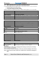
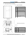
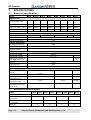
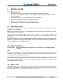
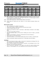
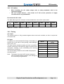
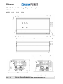
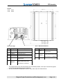
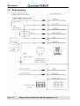
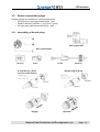
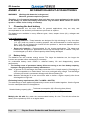
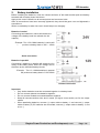
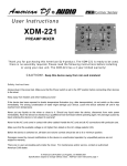
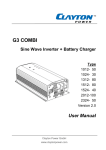
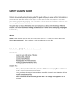
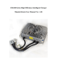
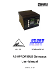
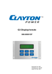
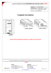
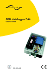
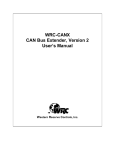
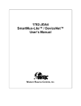
G3 - Sine Wave Inverter Type 1012 1024 1312 1512 1524 2012 2324 Version 2.0 User Manual P099-0159 Utg.1 Clayton Power Production and Development, s.r.o. www.claytonpower.com G3-Inverter Page - 2 Clayton Power Production and Development, s.r.o. G3-Inverter IMPORTANT BASIC-INFORMATION This User-Manual serves a guideline for safe and effective operation, for installation of equipment and for equipment maintenance. – It is therefore obligatory that all persons who work on or with the equipment are completely familiar with the content of this manual and follow the instructions contained herein. Installation of and work on the product may only be carried out by qualified, authorized and trained staff, familiar with the locally applicable standards and taking into consideration the safety guidelines and measures. Attention We from Clayton Power makes every effort to ensure that the information contained within this document are correct. However, our equipment is continuously being improved and updated, so we cannot assume liability for any errors which may occur. The information may contain errors or inaccuracies and represents no commitment whatsoever. Exclusion of liability Clayton Power shall in no event be liable for loss, damages or costs arising from use of this Clayton Power product, or in any way connected with faulty installation, improper operation or incorrect utilization and maintenance. Clayton Power shall in no event be liable for any direct or indirect damages, disablement or death on persons who - works with or are dependent on Clayton Power products, - are connected to medical equipment or to any life support system, where Clayton Power products is integrated as a component. Copyright The information contained within this document remains the sole property of Clayton Power No part of this document may be copied or reproduced in any form or by any means, and the information contained within is not to be communicated to a third party, without the prior written consent of Clayton Power. Clayton Power Production and Development, s.r.o. Pod Juhom 6477 911 01 Trencin Slovakia Phone: +421 322 85 00 11 Clayton Power Production and Development, s.r.o. Page - 3 - G3-Inverter Content----------------------------------------------------------------------------------Page Important basic-information......................................................................................................................3 1. Features and operation-functions ...............................................................................................5 1.1 Inverter mode:..................................................................................................................................6 1.1.1 Switch ON and OFF the inverter.............................................................................................6 1.1.2 Load search mode ..................................................................................................................6 1.2 Backup-Mode...................................................................................................................................7 1.3 LED-indications for operation and failfunctions ...............................................................................8 1.4 Device layout & status indicators.....................................................................................................9 1.5 Layout-description ...........................................................................................................................9 2.1 Specifications ..............................................................................................................................10 Electrical specification ...................................................................................................................10 2.3 Mechanical specifications ..............................................................................................................10 3.1 installation ...................................................................................................................................11 Environment...................................................................................................................................11 2. 3. 3.1.1 3.2 Mounting the device..............................................................................................................11 Cable Installation ...........................................................................................................................11 3.2.1 Battery cable .........................................................................................................................11 3.2.2 AC cables .............................................................................................................................13 3.2.3 Fusing ...................................................................................................................................13 3.3 Mechanical drawings & layout description.....................................................................................14 3.3.1 Dimensions ...........................................................................................................................14 3.4 Externel wiring ...............................................................................................................................16 3.5 Device connection-plugs................................................................................................................17 3.5.1 Assembling of Neutrik-plugs .................................................................................................17 Annex A Information about Acid-batteries .....................................................................................18 1. Choosing the best battery..............................................................................................................18 1.1 Battery sizing.............................................................................................................................18 2. Battery-installation .........................................................................................................................19 3. Battery maintenance......................................................................................................................20 3.1 Check of electrolyte...................................................................................................................20 3.2 Sealed batteries ........................................................................................................................20 3.3 Battery storage..........................................................................................................................21 Annex B Page - 4 Warranty .............................................................................................................................22 Clayton Power Production and Development, s.r.o. G3-Inverter 1. FEATURES AND OPERATION-FUNCTIONS The G3-sinewave-inverter is designed in newest powersaving technology. The device is suitable for mobile as well as for stationary application. Especially as stationary device it serves ideal as an UPS-system with uninterrupted switchover to battery powered AC-supply. So it can serve important AC-equipment in case of unforeseen loss of mains-grid without any delay. If there is no external AC-voltage available, the G3-inverter can be switched on manually to supply an accurate sinewave AC-voltage. The device can tolerate short high overload, so electric drives can be operated without risk of shutdown. As soon as no electric power is needed, the G3-inverter switches to a current save mode, but will be operable without a perceptable delay, as soon as an electric device is starting G3-sinewave-inverter for mobile application and well-suited for emergency powersystems. (UPS) • True Sine wave Inverter section • Integrated UPS functions. • Start up heavy duty loads with high peak power consumption. • Overload protection • short circuit protection on output • Over temperature shutdown • Temperature controled fan • Remote option • Datacommunication • Status indication LED in front panel • Status LED (data, remote active) in DC input endplate • Custom made to harsh environment with special lacquer coating and double galvanic separation. The G3 devices can operate in two modes: Inverter mode Energy is taken from the battery, inverted to 230VAC and delivered at output connector (grey socket). Back up mode In case of black out of AC public grid, the device will switch over automatically to inverter function and the connected equipment will still run without interruption powered by the battery. Important: for back up mode, the inverter section must be switched on! Clayton Power Production and Development, s.r.o. Page - 5 - G3-Inverter 1.1 Inverter mode: 1.1.1 Switch ON and OFF the inverter Switch ON the inverter • Push down ON/OFF power switch for about 2 seconds. Both blue and red LED will light. • After 2 seconds red LED stops and the power switch can be released. • The blue LED will flash to indicate start up sequence. • Blue LED lights and 230VAC is present. Note: If the battery is discharged, then the red LED will continue to light; - recharge battery and try again! Note: The fan is running at full speed, while the power supply is starting up for acoustic detection of the fan! Switch OFF the inverter • • Push down the ON/OFF power switch < 0.5 second. The blue LED stops lightning and the device shuts down. Remote ON/OFF • Use an external switch, to switch battery Plus to remote input of inverter on or off. 1.1.2 Load search mode In cases where it is preferable to leave the device switched on and the load is periodically inactive (switched OFF), the load search mode can be activated. In this mode the inverter is partly active and generate a short pulse every 2 second. If a load (>10W resistive) is detected, the device switches ON automatically. When a load is disconnected again the device automatically returns to search mode (low consumption) after 1 minute without load. - In load search mode the battery consumption is reduced to less than 2W in order to save battery-capacity during no load periods! Activate load search mode • Switch OFF if the inverter is activated. • Push down the power switch for > 5 seconds. • Release only when blue, and red LED starts to light at the same time. Note: in load search mode the battery consumption is reduced, while no load is active! The device switch on automatically when a load is connected (> 10W resistive) Note: there will be a small delay when connecting a load and until the device starts up automatically! Note: If load search mode is entered with a load connected, the blue LED flashes slowly only for 5 seconds (to indicate entering of load search mode), then it lights continually! Note: When a load has been connected and afterwards disconnected, the device stays fully ON for 1 minute, then it returns again to search mode (low battery consumption). Deactivate load search mode • Push power switch > 5 seconds. • Release only when Blue and red LED start to flash at the same time. Note: The load search function will remain active if the device is switched ON/OFF by remote. Note: Load search mode will also be deactivated, if battery is disconnected longer than 15 minutes. Page - 6 Clayton Power Production and Development, s.r.o. G3-Inverter 1.2 Backup-Mode In case of black out of AC public grid, the device will switch over automatically to inverter function and the connected AC-equipment will still run powered by the battery. This happens without interruption of AC-supply. Important: for backup-mode, the inverter section always must be switched on! Note: If inverter is switched to OFF, there only will be AC-voltage on AC-Output, when ACvoltage exists at AC-Input of inverter. Clayton Power Production and Development, s.r.o. Page - 7 - G3-Inverter 1.3 LED-indications for operation and failfunctions Following three LEDs, located at frontside of device, indicates different status of functions and failures. • The blue LED is for he inverter section • The green LED is fort he charger section • The red LED indicates the status of battery Different conditions are identified by steady or different blinking lights by one or more LEDs. Blue LED Description. ON Inverter is running 1 Short flash every 2. second Load search mode 1 Flash continuously Inverter output is overloaded 2 Flash continuously Inverter temperature is too high. (automatic cooling down and restart) 3 Flash continuously Short circuit at inverter output 4 Flash continuously Short circuit in power supply 5 Flash continuously Overload in power supply while starting up Green LED Description. ON Battery fully charged – maintenance charging Slow flashing Charger is in absorption phase of charging (top charging) Fast flashing Charger is boost charging 1 Flash continuously Mains present but too low (< 185VAC) or not clean, no good sine-wave 2 Flash continuously Mains too high (> 265VAC) Red LED Description. No light Battery voltage okay ON Battery voltage too low (inverter will switch off within 1 minute, to prevent a deep downloading of battery) Flashing Battery voltage too high All LED together Description. ON Not used (reserved for future use) Fast flashing Remote control and Power button on at the same time 1 Flash continuously NTC error (internal temperature sensor) 2 Flash continuously Poor connections or disconnection of battery during charging 3 Flash continuously Half bridge failure 4 Flash continuously Full bridge failure Red and Green LED together Description. 4 Flash continuously Temperature sensor (NTC) missing. Will also be shown for 20 seconds after switching on AC-supply, if no sensor is adapted. WARNING! Never disconnect cables during charging (and inverting) especially near the battery bank. The battery can explode! Never discharge a battery completely; it will cause permanent damage of the battery! Note: batteries must be able to deliver min. 12W and min. 10,3V before charging can start! Page - 8 Clayton Power Production and Development, s.r.o. G3-Inverter 1.4 Device layout & status indicators 1.5 Layout-description G3 Inverter Pos. Description 1. ON/OFF Power Switch 2. Inverter LED – Blue 3. Battery LED – Red 4. Positive voltage DC input terminal 5. Negative voltage DC input terminal 6. External DATA connector RJ12 type (6p6) 7. External DATA connector RJ12 type (6p6) 8. External DATA connector type PHOENIX MSTBA 2,5/ 3-G-5,08 9. AC inverter output connector, type NEUTRIK ( Grey ) LEDs between data-connectors Auxiliary LED Description Pos. Color Function A Green Lights when Data link is “High” B Yellow Lights when Data link is “Low” C Orange Lights when remote is ON D not used Clayton Power Production and Development, s.r.o. Page - 9 - G3-Inverter 2. SPECIFICATIONS 2.1 Electrical specification Model 1012 1312 1512 2012 1024 1524 2324 2336 POWER OUTPUT Continuous output power FTS (Full Temperature Scale) 1000 W 1300 W 1500 W 2000 W 1000 W 1500 W 2300 W 2300 W Output power surge ( 1 sec. ) 2000 W 3000 W 3000 W 4000 W 2000 W 3000 W 3000 W 4000 W Output power surge ( 10 sec.) 1500 W 1800 W 2000 W 2800 W 1500 W 1800 W 3000 W 3000 W Output power surge ( 15 min.) 1200 W 1500 W 1700 W 2200 W 1200 W 1700 W 2500 W 2500 W 15 W 17 W Max. efficiency 90% CONSUMPTION No load power consumption 10 W 15 W 10 W Load search mode consumpt < 2W Sleep mode consumption < 5mA THERMAL MANAGEMENT Max operating temperature +50°C Min operating temperature Max internal temperature (inverter shut down) +80°C -20°C VOLTAGE OUT Nominal output voltage 230 VAC Output Voltage tolerance -10% to +5% Output Voltage tolerance (at input voltage 25V to 31.5V) -18% bis +5% Frequency 50 Hz Output wave form Sinus THD max. 3% VOLTAGE IN Battery input voltage (nominal) 12 VDC 24 VDC 36 VDC Max input voltage 15 VDC 30 VDC 45 VDC 10,5 VDC 21 VDC 25 VDC 9 VDC 18 VDC 23 VDC 12,75 VDC 25,5 VDC 38,25 VDC Low battery voltage cut-off (Slow reaction 3 Sec.) Low battery voltage cut-off (Fast reaction <10mS) Voltage before inverter can switch ON again (after a low battery cut-off) 2.3 Mechanical specifications Model 1012 1312 1512 2012 IP-class 1024 1524 2324 2336 IP 20 Dimension of cabinet (L x W x H) mm 299 x 198,2 x 116 376 x 198,2 x 116 299 x 198,2 x 116 376 x 198,2 x 116 Dimension incl. terminals (L x W x H) mm 334 x 198,2 x 116 412 x 198,2 x 116 334 x 198,2 x 116 412 x 198,2 x 116 6 7,5 Weight (kg) Page - 10 6 7,5 Clayton Power Production and Development, s.r.o. G3-Inverter 3. INSTALLATION 3.1 Environment • • • • • • The inverter must be placed in a dry, well ventilated and dust free location. Place the unit as close as possible to the battery in order to keep the battery cables as short as possible. Do not place the unit in same compartment as the batteries. Make sure that water or dust can not enter the cabinet. Ensure that the air flow from fan is not obstructed. Avoid mounting the device next to flammable materials. 3.1.1 Mounting the device The unit can be mounted on a wall, or flat mounted (4 x Ø5mm holes). - Optimum cooling is obtained in vertical position. Make sure that each wire used in the installation has at least the same intersection and correct length, as given in this manual! During wiring use standard cable fixtures and wire ducts. Do not bent extremely the cables/wires, and avoid sharp edges to prevent the isolation of the wires/cables from cutting and abrasion. Keep in mind that usage of too long battery cables and dirty or loose connections may produce a significant voltage drop, which would cause that the device shut down for under voltage, even if the battery is ok! 3.2 Cable Installation ATTENTION Electric installations should only be done by accordingly skilled workers EMC The wiring of the cables is influencing the EMC behavior of the system, in which the inverter is a component. This is due to the fact that the cables are receiver and transmitter antennas of radio frequency and electromagnetic interference. Good EMC properties are obtained in the following way: Place the cables in a metal rail. The metal offers resistance against interference currents. The battery cables should be placed close to each other to reduce looping area. Cables from different groups should not be twisted, but be placed parallel with each other. 3.2.1 Battery cable The cable length (up to 3 meter) between the battery and the combi must be sized according to the table at next page. The values are given by a criterion to keep the total cable voltage drop lower than 250mV at max nominal power delivered by the combi. Clayton Power Production and Development, s.r.o. Page - 11 - G3-Inverter Recommended cross-section of battery-cables Wire size Type of device mm2 AWG 1012 15 5 - 1,5m 25 3 1,5m 2,5m 1,5m 35 2 2m 1,5m 1,5m 3m 2,5m 1,5m 50 1/0 3m 2m 2m 1,5m 3m 2m 70 2/0 - 3m 2,5m 2m 1312 1512 2012 1024 1524 2324 3m Note: When starting up heavy load with high inrush current (compressors, motors, etc) it is recommended to use cables with a even higher intersection (or shorter length) to prevent under-voltage shut-down of the device Note: Avoid cables longer than 3 meters between battery and inverter.! Note: Cable length are defined per each cable (or as the distance between battery and inverter). Mounting DC-cables • • • • • • • • • • PAY ATTENTION TO CORRECT POLARITY! Check that the battery voltage matches the DC input to the inverter. Check the battery poles are clean. Prepare good electrical contact, use brass or lead battery connectors at the battery poles. Connect only one cable at the time. Start with the Black cable (-). First connect to battery pole, then to inverter (-) terminal (black). Double check that Black (-) cable are connected to the correct terminals (-). Secure there is no risk of short circuit! Connect Red cable (+). First connect to battery pole, then to inverter (+) terminal (red). When connecting the cables a spark will occur. Avoid sparks near the battery! WARNING! • Do not interchange the battery cables. It will result in instantaneous damage of the unit. Such damage is not covered by the guarantee. • Do not connect inverters at the AC-output in parallel. It will damage the units. Such damage is not covered by the guarantee. • Do not connect AC generator or AC mains to the units AC output connector (grey Neutrik). It will damage the unit. Such damage will not be covered by the guarantee. Page - 12 Clayton Power Production and Development, s.r.o. G3-Inverter 3.2.2 AC cables • When installing the AC cables always refer to safety standards valid in the regarding country! • The use of RCD devices – also known as FI fail current protection is highly recommended in any installation! Recommended AC cable The table below gives the minimum recommended wire sizes of the mains cable! Device type AC cable 1012 1024 1312 1512 1524 2012 2324 17 AWG 17 AWG 15 AWG 15 AWG 15 AWG 15 AWG 15 AWG AWG 15 = 1.5mm2 AWG 17 = 1.0mm2 3.2.3 Fusing AC output The inverter section is fully protected against short circuit and overload, no fuse is required at AC output side. DC input In addition it is recommended the fusing of the battery to prevent fire in the case of wrong wiring, cable damage, short circuit, etc. 1012-50 Battery fuse rating 125A slow-blow The fuse must be located to battery as close as possible, and the screw joints must be firmly tight to prevent loose connection, resulting in joint overheating and reducing the efficiency of the fuse. 1024-30 80A slow-blow 1312-80 175A slow-blow 1512-80 175A slow-blow The current rating related to each model is displayed in the table beside: 1524-40 100A slow-blow Note: The battery fuse does NOT prevent damage in case of reversed battery polarity; such damage is not covered by the guarantee! 2012-100 250A slow-blow 2324-50 150A slow-blow Model Clayton Power Production and Development, s.r.o. Page - 13 - G3-Inverter 3.3 Mechanical drawings & layout description 3.3.1 Dimensions MODEL Page - 14 1512 2012 2324 Clayton Power Production and Development, s.r.o. G3-Inverter MODEL 1012 1024 1312 1524 _________________________________________ Pin 1 RJ12-Typ Pin# 1 1 Pin1 – Phoenix Combicon Signal Description - TEMPX1 Temperature sensor 3 + TEMPX1 Temperature sensor 4 SYNC_IN/OUT Used in option SYNC only DATA Single Wire Clayton Communication 6 1 Signal DATA User GND ( Fused ) 2 5 Pin# REMOTE 2 REMOTE Description Single Wire Clayton Communication Connected to plus pole of the battery switches on the combi Not connected = no influence 3 not used ( option )2 Connection to plus pole of the battery switches on the combi. Not connected = no influence 1 2 The signal wires of the two connectors are connected parallel, so the pin out and the signals on the correspondending pins are identical. Will be introduced and defined in future, only in the case of Combi devices. Clayton Power Production and Development, s.r.o. Page - 15 - G3-Inverter 3.4 Externel wiring Page - 16 Clayton Power Production and Development, s.r.o. G3-Inverter 3.5 Device connection-plugs Following plugs are available for external connections • AC-Output plug type Neutrik NAC3FCB – grey • Phoenix data-plug, MSTB 2.5 / 3-ST-5.08 – green • AC-Input plug, type Neutrik NAC3FCA – blue 3.5.1 Assembling of Neutrik-plugs Wire preparation Wire connections Housing Insert A-Type Plug in (blue) Chuck Bushing B-type plug-in (grey) (only for Combi-models) Engage Separate Clayton Power Production and Development, s.r.o. Page - 17 - G3-Inverter ANNEX A WARNING! INFORMATION ABOUT ACID-BATTERIES Working with batteries is dangerous! Batteries generate explosive gasses! Therefore it is of outmost importance that each time you serve equipment in the vicinity of the battery, to follow the battery instructions very accurate. Never smoke or allow a spark or a flame in the vicinity of a battery. 1. Choosing the best battery Lead acid batteries are the best choice for general applications; they are easy and uncomplicated to use and their performance to price ratio is superior. The batteries are available in many different types, sizes, ampere hours (Ah), voltages and chemistries. Lead acid battery types • Starting batteries - These batteries are designed for high discharge in very short time (1~2 min.) and only used for cranking purpose. Not recommended for inverter applications. They will not damage the inverter but the problem is, that these batteries will not last in deep cycle applications. • Deep-cycle batteries - Recommended for the inverter applications. The deep-cycle batteries are designed for applications where high discharge rate is needed. They can be discharged up to 80% of rated capacity without being damaged. 1.1 Battery sizing The batteries are the inverters energy source. The larger the batteries are, the longer the inverter can operate before recharging is necessary. An undersized battery bank results in reduced battery life and disappointing system performance. • The leading cause of premature battery failure are wrong or too less battery-capacity, improper charging and poor battery maintenance. Note: In general do not discharge the battery more than 50% of rated capacity. Discharging of 80% is acceptable on a limited basis, such as a prolonged utility outage. Total discharge of battery will result in permanent damage and reduced battery life. Note: Batteries discharged at a low rate will be able to deliver a higher capacity than those discharged at a high rate Estimating battery requirements (VOLT x AMPS = WATTS): The watt ratings of each appliance powered by inverter must be added together. Use the figures from the nameplate label on the appliance. Needed battery capacity (Ah) = Total watt consumption (W) x Running time (Hours) Battery voltage (V) x 0,9 (Eff.) Multiply the Ah with 2 to reach the recommended battery Ah size. This will also allow the battery to be cycled only 50% on a regular basis. Page - 18 Clayton Power Production and Development, s.r.o. G3-Inverter 2. Battery-installation Before installing the batteries, clean the contact surfaces of the lead terminal post and battery terminals with a battery brass wire brush. Apply a thin coat of Vaseline to all contact points and connector bolts. After all connections have been securely tightened; they should be gone over and tightened a second time. When a new battery is taken into use it should be put on charging! Batteries in serial Connecting two batteries in series will double the voltage of the battery bank but maintain the Ah capacity. Example: Two 12V 100Ah batteries in series will l produce a battery bank of 24V – 100Ah Serial connection Batteries in parallel Connecting 2 batteries in parallel will double the Ah rating of the battery bank, while the voltage will be the same as the individual battery blocks. Example: Two 12 -100Ah batteries in parallel will produce a battery bank of 12V-200Ah Parallel connection Important: • Only similar batteries must be connected together in a battery bank. • Do not connect old and new batteries together. • Do not connect flooded and sealed batteries together. • Keep all interconnections short and in same (or higher cross section) as for the output cables. • When paralleling batteries, connect (+) output cable to battery 1, and connect (-) output cable to battery 2 (If 3 batteries are connected, connect (-) output cable to battery 3, and so on...) Clayton Power Production and Development, s.r.o. Page - 19 - G3-Inverter 3. BATTERY MAINTENANCE Performing preventive maintenance on batteries is easy and should occur at least once a month during hot weather and every three months in cold weather. In the case of lead acid batteries the maintenance should include check the electrolyte level for non-sealed wet batteries and the State of Charge (SOC) with hydroscope measurement of specific gravity of the electrolyte and recharging the battery if necessary. A clean well kept battery will extend the useful life of the battery. Remove dirt and dust accumulations from the top of the battery. Wash the top of the battery with clean hot water and soda solution to neutralize any acid accumulation. Baking soda used in the home is satisfactory. Rinse with clean water and dry. Ensure vent caps are in place and no soda enters the battery. As a part of the maintenance always tight loose hold-down clamps to prevent excessive vibration, battery lugs, terminals and connectors. 3.1 Check of electrolyte In the case of regular or low maintenance batteries: - Check the height of the electrolyte twice a month. If necessary replace with approved water only - use of non-distilled water can cause mineral build-up in the battery cell. NEVER fill batteries with seawater, as DANGEROUS CHLORINE GAS will be liberated. Never fill the cells above the bottom of the vent (observe the regarding information of battery-manufacturer). Overfilling will cause loss of electrolyte and reduce the battery capacity. Preventive maintenance involves as a minimum to check the cell electrolyte level for correct acid volume once a month and equalizing once every six months. 3.2 Sealed batteries In the case of sealed battery, the state of charge can be practically evaluated by measuring open cell voltage, with a digital multi-meter. This method is however not 100% reliable, because sulfating of the battery may result the increased voltage on the terminal. Than not fully charged batteries should be considered for fully charged. – Use a special testing instrument, available from a battery-dealer. Before reading out the open cell voltage, the surface charge has to be removed. – The recommended method is to allow to rest the battery without charging or discharging for between six to twelve hours at room temperature if possible. Summary of maintenance Secure the batteries always are fully charged. Batteries must not be left discharged for longer period without charging. Recharging on regular basis tends to prevent irreversible permanent sulfating Open / Wet batteries need topping up with distilled water frequently. Use protective goggles and rubber gloves, when working with batteries (acid) Clean battery top and poles. Use anti corrosion oil or Vaseline on pole bolts to preserve the surface. Remove any corrosion, lead oxidation, paint or rust with a battery brass wire brush Don’t place the batteries in hot areas. Check min once a year the pole bolts are well tightened. Page - 20 Clayton Power Production and Development, s.r.o. G3-Inverter Replace the battery if the battery case is bulging, cracked or leaking. 3.3 Battery storage Lead-acid batteries must be stored in the open-circuit condition with the terminals insulated. Long periods of storage at even low drain rates may result in permanent damage. Batteries should be stored in cool, dry and frost-free environments in their upright position. Batteries that will be stored for extended periods should undergo regular open-cell voltage checks and be recharged as necessary. – This recharging will also prevent the build up of the damaging process of sulfating of the battery. Continuous float charging or periodic recharging will prevent batteries from freezing. • Do not store the lead acid batteries in discharged state • Batteries should be kept at least 3/4 charged, especially during winter weather. Clayton Power Production and Development, s.r.o. Page - 21 - G3-Inverter ANNEX B WARRANTY Installation, operation, technical support, warranty and service issues should in the first case be directed towards the outlet at which the Clayton Power devices are purchased. CAUTION & WARNING: DO NOT USE OR ATTEMPT TO USE THIS PRODUCT UNTIL YOU HAVE READ THIS USER'S MANUAL IN ITS ENTIRETY. IMPROPER INSTALLATION OR USAGE OF THIS DEVICE MAY BE HAZARDOUS AND MAY CAUSE DAMAGE TO OTHER ELECTRICAL EQUIPMENT AND WILL VOID WARRANTY. Clayton Power warrants, to the original purchaser only, for a period of 24 months from the date of purchase, that the Clayton Power device will be in good working order when properly installed and operated as described in this manual. If the inverter fails within this time period under normal use, Clayton Power will, without charge, at the place of Clayton Power's choosing, repair or replace the inverter - with new or reconditioned parts or a new or reconditioned inverter as Clayton Power deems necessary. This warranty is void and will not be applied if: • The inverter has been used against the recommendations of this manual. • The inverter has been used in an application outside of general automotive, solar, industrial or marine applications without the agreement of Clayton Power. • The inverter has been modified or repaired without written authorization of Clayton Power. • Reverse polarity, excessive overloading, general abuse, neglect, wear & tear, ingress of liquids (water, oil, acid, or otherwise), foreign objects, lightening strikes, over or under voltage, RFI/EMI, etc. Obtaining Warranty Service To obtain warranty service, please contact the outlet at which the product was purchased. Do not contact Clayton Power directly. For warranty service you will require the following: 1. Proof of purchase 2. Model number 3. Serial number 4. Brief description of application and problem. Telephone your Clayton Power dealer for an authorization number prior to dispatch. Do not send without authorization. Once this number has been obtained, please carefully package your inverter and send to the Clayton Power dealer. Page - 22 Clayton Power Production and Development, s.r.o.