1
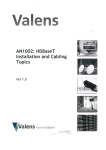
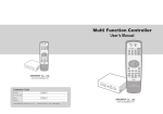
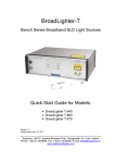
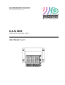
SALZBRENNER STAGETEC Audio Video Mediensysteme GmbH C.A.S. SCB CAS-1018 and CAS-1019 User Manual English Serial No. Öffner - Break RLY a RLY b TrS+ LS+ TrP - TrP+ Line B Line B+ Line A Line A+ Data Data+ 0V Earth +18..36V Schließer - Make Option Icons Used in This Manual: Indicates dangerous situations that may affect your health or damage the system. Indicates dangerous situations that may seriously affect your health or situations where you life is in danger. Warning! Indicates situations that may affect proper operation or may void your warranty. Disclaimer: The manual has been carefully checked and is believed to be accurate at the time of publication. However, no responsibility is taken by Salzbrenner Stagetec Audio Video Mediensysteme GmbH for inaccuracies, errors, or omissions, nor is any liability assumed for any loss or damage resulting either directly or indirectly from the provision, representation, or use of the information contained within it. Further, the Salzbrenner Stagetec Audio Video Mediensysteme GmbH does not give any expressive or immanent warranties for the documentation itself, including, but not limited to, the warranty that this documentation complies with the usual standards and may be appropriate for a certain purpose. Neither presence nor absence of trademark or brand designations or trade descriptions in this manual should be regarded as affecting the legal status of any trademark. All rights reserved. No part of this document may be reproduced, adopted, stored, transmitted, or translated in another language, without prior written permission, unless otherwise specified by copyright laws. 2nd edition, September 2003 Printed in Germany Order reference: C.A.S. SCB User Manual Order code: CAS-3016 Subject to change without notice. Contents 1 Safety Instructions 1 2 Operating Instructions 3 3 Warranty 4 3.1 Introduction...................................................................................... 4 3.2 Warranty .......................................................................................... 4 3.3 Warranty Limitations......................................................................... 4 4 Installation 4.1 Location........................................................................................... 5 4.2 Installation ....................................................................................... 5 5 Features 7 6 Connections and Operation 8 6.1 Supply-Voltage Application ............................................................... 8 6.2 Data Line ....................................................................................... 10 C.A.S. SCB 5 Contents i-1 i-2 Contents 6.3 100-V Signals and the Speaker ....................................................... 12 6.4 Control Relay ................................................................................. 13 7 Troubleshooting 7.1 The Analyzer cannot find an SCB..................................................... 14 7.2 The relays do not close................................................................... 14 7.3 The relays do not drop out .............................................................. 15 7.4 The control-relay contact is continually open................................... 15 8 Service and Repairs 8.1 Inside Servicing .............................................................................. 16 8.2 Cleansing ....................................................................................... 16 9 Specifications 9.1 Electrical Specifications.................................................................. 17 9.2 Physical Specifications ................................................................... 18 9.3 Environmental Conditions ............................................................... 18 14 16 17 10 Order Codes 19 11 Index 20 C.A.S. SCB 1 Safety Instructions • No user-serviceable parts inside. Never open the covering. • Never insert any items into the ventilation slots or other openings of the device. Never try to access any inside parts for repair, service, or other reasons. • Never position any containers with liquids onto the device. If liquids or items have been inserted into the device, disconnect it from the mains and have it checked by a technician authorized by Salzbrenner Stagetec Audio Video Mediensysteme GmbH before reconnection. • Make sure that the device is properly ventilated. Never put any items onto the device. • Make sure that no heavy items are put onto the mains cable or any connection cables. No cables must be caught by heavy items such as the device housing or a rack. • Do not operate the device in places where it is exposed to dust or excessively high humidity, to reduce the risk of fire or electric shock. • When disconnecting the device, never pull the cable. Pull the plug only. Damaged cables may cause fire or an electric shock. • Arrange your cables in a way that nobody can walk on them or stumble. • Avoid overloading the mains socket by using power strips to reduce the risk of fire or an electric shock. • The power cable of the device features a 3-pole plug in order to reduce the risk of an electric shock. Connect it only to a properly earthed power point. Never use any adapters. Never tape the ground contact. When using an extension cable, use a 3-core cable only. • Condensation may occur inside the device when it is moved from a cool to a warm location. In this case, wait at least 6 hours before connecting the device to the mains. • This device contains a lithium battery. There is danger of explosion if the battery is incorrectly replaced. Have the battery replaced only by a qualified technician authorized by Salzbrenner Stagetec Audio Video Mediensysteme GmbH. The concerning addresses can be found on the inner part of the back cover. Discard used batteries according to the manufacturers instructions. C.A.S. SCB Safety Instructions 1 • Do not connect the device to telecommunication networks. • Never operate the device in explosive areas or those with aggressive atmosphere. • Make sure that the device is connected only to an appropriate power-supply unit. Failing to do may cause heavy damage to the device. • Condensation may occur inside the device when it is moved from a cool to a warm location. In this case, wait at least 6 hours before connecting the device to the mains. • Never use autotransformers as speaker transmitters as this may result in a current path from the device to the grounds. Touching a single core of a 100-V line may then result in fatal injuries. 2 Safety Instructions C.A.S. SCB 2 Operating Instructions With regard to the features and specifications of this product, the C.A.S. SCB can be used for monitoring a single speaker, for toggling between two 100-V audio signals, and as a lowvoltage control switch. C.A.S. SCB is no autonomous apparatus. A C.A.S. Analyzer and a DC-voltage source are required for operation. In addition, if the line-monitoring facility is to be employed, a C.A.S. Generator is required. The C.A.S. SCB is put into operation using the items required for putting the Analyzer into operation; no other items are required. The manufacturer is not liable for reduced performance, malfunctions, or damages that occur due to • • • • • • • Warning! improper or inadequate servicing executed by the customer, software provided by the customer, unapproved alterations, operation in locations that do not comply with the operating conditions for this device, operation not complying with the electric specifications, improper installation, damages resulting from improper packaging by the customer. Any repair work, battery replacement, modifications, and extensions are exclusively performed by Salzbrenner Stagetec Audio Video Mediensysteme GmbH or an authorized person or institution. C.A.S. SCB Operating Instructions 3 3 Warranty 3.1 Introduction C.A.S. SCB is manufactured exclusively using selected high-quality components. Each device undergoes a 100% production check. Thus, it is guaranteed that every product is shipped in an absolutely perfect condition. 3.2 Warranty Salzbrenner Stagetec Audio Video Mediensysteme GmbH warrants to the original purchaser that the product is free from defects in material and workmanship for the period commencing upon the date of purchase and continuing for the following period of time after that date for 12 months. During this period, Salzbrenner Stagetec Audio Video Mediensysteme GmbH is entitled • • • • to repair, to replace with a repaired product, to replace with a product of the same or a better functional quality, to return the purchase price after receiving the defect product, any defective product. A copy of the original sales receipt must be produced for any service under warranty. 3.3 Warranty Limitations Salzbrenner Stagetec Audio Video Mediensysteme GmbH does not give any further express or implied warranty for the product in question. Salzbrenner Stagetec Audio Video Mediensysteme GmbH expressly denies any implied warranties that this product is of conventional quality and will be fit for a certain purpose. Some states do not allow limitations of how long a warranty lasts, so above limitations may not apply to the purchaser. In this case, however, the implied warranty that this product is of conventional quality and will be fit for a certain purpose is limited to 12 months, as this written warranty is. 4 Warranty C.A.S. SCB 4 Installation 4.1 Location The device is designed for wall or ceiling installation. In addition to and beside the safety instructions, make sure to observe the following: • The surrounding temperature at the selected location must not exceed 40°C/104°F. Please note that strong heat sources such as radiators may make the surround temperature surpass the critical mark, even if the average temperature inside the room is below 40°C. • The installation location must not be exposed to dust or high humidity. • The device must not be exposed to direct sunlight. • Make sure to prevent the backplane connectors from direct access during operation as dangerous voltages may occur there. • Never apply excessive force to the connections; if necessary, use third-party components for protecting the connections from forces. • The location must never be exposed to strong vibration. • Never expose the device to strong magnetic fields as this may block the relays and result in short circuits. Danger of fire and electric shock. Such magnetic fields do occur primarily near loudspeakers and transformers. Further, make sure to observe the following when mounting units without housings supplied: • The conductor board and the contained components must not be damaged. • Never touch the conductor board in normal operation. • Make sure to prevent dust or dirt from covering the conductor board and the contained components. 4.2 Installation The C.A.S. SCB does not feature DIP switches for address setting nor trim controls for inputsensitivity adjustment; identification of the individual units is realized rather via the serial number. There are two cases for recording the installation location: 1. 2. You already know in advance where which unit will be mounted. In this case, set up a list. Take the required unit out of the package, remove the protective bag, note the serial number on the list, and mount the device at the intended location. You mount the units randomly at any places. In this case, note the serial number and the respective location on the list immediately after installing a unit. You may also put one of the supplied stickers onto the list. C.A.S. SCB Installation 5 Warning! It is vital for your system to work that you know and record the exact location of each SCB unit. If a malfunction occurs during operation, the serial number of the unit in question will be displayed. You must then be able of locating the respective unit. If an SCB unit is mounted in a hidden place, the serial number cannot be read after installation. In such case, you may want to put the second sticker containing the serial number on a visible place on the unit. 87.5 67.0 46.0 10.5 For mounting the device, bore two holes at the mounting location (refer to the pattern below for the exact positions) and fix the SCB with two appropriate screws (max. diameter: 4 mm). 68.0 88.6 98.0 In order to physically establish the connections, remove 6…7 mm/¼" of sheathing from the wires. Insert a screwdriver (3 mm blade width) into the respective terminal-board opening above the terminal hole and pull the screwdriver handle upward to pull the blocking spring. Insert the wire into the terminal hole and remove the screwdriver to release the spring. The wire should now be fully locked in the terminal. Make sure not to insert the sheathing. The spring terminal of the unit is suitable for both single-core and multi-core conductors. 6 Installation C.A.S. SCB 5 Features The C.A.S. SCB allows for monitoring a single speaker for idling or short-circuits. In addition, the device can be used for switching between two 100-V audio signals and for controlling an independent device. The special features are as follows: 1. High-dynamic auto-adjusting voltage monitoring The SCB monitors the coil of a single speaker for idling or short-circuit. For this function to work, a 20-kHz pilot tone must be layered onto the audio signal. When the device is initially put into operation, the sensitivity of each SCB unit is individually adjusted, so varying speaker impedance and the frequency response of transmitters used do not affect the selected shortcircuit and idling limits. All settings are stored to a non-volatile memory. Thus, speakers of a power range between 1…60 W can be connected to the SCB. 2. Software-controlled selection between two 100-V signals Using the Analyzer, the status of the speaker can be queried, or one of two 100-V signals can be routed to one out of two lines; the speaker can also be completely disabled. 3. Potential-free relay contact for general control purposes In addition, each SCB features a relay including a contact intended for general control purposes. The relay configuration is set individually using the software. 4. Remote-control facilities using the adapted RS485 bus An adapted version of the RS485 bus is integrated. This significantly increases insusceptibility against interference and reduces the effect of excessive voltage drops onto datacommunication functions. 5. No DIP switches for address setting The SCB does not feature error-prone DIP switches for address setting but employs an installation-friendly “electronic” address. 6. Easy-mount connectors All connections are made without soldering but using spring terminals incorporated on the module frame. However, a soldering-joint version can be supplied, too. 7. Extended supply-voltage range The SCB is operated with a supply voltage between 18…36 V. SCBs without relays can even be operated with a minimum voltage of 12 V. C.A.S. SCB Features 7 6 Connections and Operation Schließer - Make Option Serial No. Öffner - Break RLY a RLY b LS+ TrS+ TrP+ TrP Line B Line B+ Line A Line A+ Data Data+ 0V Earth +18..36V Jumper for control relay LED termination block The adjacent image shows the elements of the C.A.S. SCB. All terminals, the connections of which may be passed through to another SCB, are implemented two times, thus providing for easy wiring. The jumper bar is important only in case that a control relay is present; it allows for selecting whether the NCC or NOC is available at the “RLY a” and “RLY b” terminals. The LED can be enabled or disabled only via the PC software. If you are looking for a certain SCB unit, turn the respective LED on to remotely identify the unit in question. 6.1 Supply-Voltage Application The C.A.S. SCB operates with an extended supply-voltage range of 18…36 V. SCBs without relays can even be operated with a minimum voltage of 12 V. Therefore, voltage drops occurring on the supply line will not affect the operation of the devices. However, there are some points that need to be +18..36V + considered. All SCBs relate to the supply-voltage reference. The adjacent image shows how this 10k voltage is generated. It is essential for all SCBs to get the identical reference voltage, that the positive Ref Earth and negative supply lines show equal conductor diameters and lengths, and that all SCBs are 10k supplied by the same voltage source. The first two provisions will easily be met, however, multiple 0V power-supply units may be required; in this case, all Earth terminals must be interconnected in order to make sure that all SCBs have the same reference potential. (This interconnection may be established in the other case.) We recommend to employ the grounding core of the connecting cable, or the sheathing respectively, for this purpose. 8 Connections and Operation C.A.S. SCB This provides for two ways of wiring: 2. without reference conductor (when using a single power-supply unit) with reference conductor (when using multiple power-supply units) another SCBs zutoweiteren SCBs 0V 0V +18..36V to another zu weiterenSCBs SCBs +18..36V 3. 0V +18..36V toweiteren another SCBs zu SCBs The output voltages of the individual power-supply units must be potential-free. C.A.S. SCB Connections and Operation 9 6.2 Data Line The data line transports an asynchronous serial signal with a rate of 9,600 baud. The data line must have a line impedance of 110Ω and a maximum length of 1,000 meters/3,300 ft. Besides, it must feature a terminating resistor of 110Ω at its end. No terminating resistor is required on the Analyzer side as the Analyzer itself includes such a resistor. As the Analyzer includes eight equal data-bus terminals, up to eight different data lines can be established between the Analyzer and the SCBs. A limited data-line split-up into multiple lines is possible by combining all lines directly at the Analyzer. The terminating resistors can be added up according to the number of lines, e.g. when setting up two lines, each line must have a terminating resistor of 220Ω, while a 330-Ω resistor is to be used for each of three lines. We recommend not configuring a split setup with more than three lines. Wiring examples: DCF77 5V SPKR DATA BUSSES SUPPLY +5 - +6 - +7 - +8 - + EXT + 1 - + 2 - + 3 - + 4 - + DIR - NC C.A.S. Analyzer N +18..36V 220R 0V 220R power supply unit The 100-V lines were omitted in the above image to show the essence. The dotted lines indicate multiple subsequent SCBs. We want to point out again that two branched lines will make sense only if all Analyzer data busses are in use. 10 Connections and Operation C.A.S. SCB For data lines shorter than 50m, you have to add a condenser (C=2,2nF) in parallel to terminal resistor. ANALYZER SCB 1 Warning! SCB n Speaker Control Board at end of line C = 2,2nF R = 110 Ohm Data C.A.S. SCB Connections and Operation 11 6.3 100-V Signals and the Speaker Here, one must distinguish between C.A.S. SCBs with and without selective switch. If no selective switch is available, only a single 100-V core pair can be connected to the LINE A terminal, which is directly linked to TrP+ and TrP–. However, the power that can be transmitted through that line is limited, so we suggest connecting the transmitter directly to the 100-V line. In this case, the wiring would look like this: P- P+ S+ S- + - 100V The LINE A+, LINE A–, LINE B+, and LINE B– terminals are not used. If, however, the selection facility is integrated into the SCB, the wiring must look like this: to another SCBs P- S+ - P+ S+ + - + 100V 100V A B Line As an alternative, the lines can be connected in the same way with SCBs without selective switch; however, only line A can be used in this case. Note the maximum power allowed for the 100-V terminals. For more information, refer to chapter 9.1 “Electrical Specifications”. The length of the cables between the secondary terminals of the employed transmitter, the SCB, and the speaker should not exceed 2.5 m/8'. Never use autotransformers as speaker transmitters but only transformers with separate primary and secondary windings; failing to do so may result in a current path from the device to the grounds. Touching a single core of a 100-V line may then result in a fire or the destruction of the device. 12 Connections and Operation C.A.S. SCB 6.4 Control Relay potential free contact The control relay includes a single-pole switch contact. However, it is possible to use either the NCC or the NOC. Use the jumper next to the terminal bar for selecting which contact is available at the “RLY a” and “RLY b” terminals. NO NO NC NC The control relays are not suitable for separating voltage nets. Therefore, connect only potential-free sources and loads. Further, note the allowable control-relay voltage and current ranges as listed in the specifications in chapter 9.1 “Electrical Specifications”. C.A.S. SCB Connections and Operation 13 7 Troubleshooting 7.1 The Analyzer cannot find an SCB Possible reasons: 1. 2. 3. The operating voltage is missing, too low, or has the wrong polarity. Wrong reference voltage. Improper data-line connection. Actions: 1. 2. 3. 4. Make sure that the DC voltage between the positive and the negative socket connector is within an acceptable range. Check whether the Earth connector shows a supply voltage of half the voltage present at the 0V connector. If not, temporarily detach all conductors from the Earth terminal and repeat the check. If the voltage present does still not correspond to half the positive supply voltage, your SCB is defective; else, an error with the external wiring has occurred. Do not forget to reconnect the Earth lines before putting the device back to operation. If multiple power supplies are employed, make sure that all SCBs in use show an equal reference voltage. Check whether all data lines have the same polarity. 7.2 The relays do not close Possible reasons: 1. 2. Low operational voltage. The SCB is located near a strong magnetic field. Actions: 1. 2. 14 Troubleshooting Measure the operational voltage. SCBs including relays require an operational voltage of at least 18 V. In some cases, the operational voltage will fall below the allowable range only when the relays of many SCBs are closed. This behavior suggests a too small conductor diameter or a too weak power supply. Make sure that there is an appropriate gap between the SCB and any present strong magnetic field (e.g. near loudspeakers or transformers) by moving the SCB away from the assumed magnetic-field source. If you can hear the relay snapping, decide on a different location for mounting the SCB. C.A.S. SCB 7.3 The relays do not drop out Possible reason: The SCB is located near a strong magnetic field. Action: Make sure that there is an appropriate gap between the SCB and any present strong magnetic field (e.g. near loudspeakers or transformers) by moving the SCB away from the assumed magnetic-field source. If you can hear the relay snapping, decide on a different location for mounting the SCB. 7.4 The control-relay contact is continually open Possible reason: The control-relay jumper is missing. Action: Insert a jumper into the jumper bar on top of the LED. C.A.S. SCB Troubleshooting 15 8 Service and Repairs 8.1 Inside Servicing There are no user-serviceable parts on the modules. Any repair, modification or extension works must be exclusively carried out by Salzbrenner Stagetec Audio Video Mediensysteme GmbH or an individual or institution authorized by Salzbrenner Stagetec Audio Video Mediensysteme GmbH. 8.2 Cleansing Cleaning the device is not required under normal conditions. However, if a dust cover has emerged on the terminal board, the soldered joints, the jumper bar, and the LED after prolonged use, blow it away using compressed air. Warning! 16 Service and Repairs Never use scoring agents or cloths. Never use thinners or cleaning agents containing solvents or alcohol, benzene, and especially acetone! C.A.S. SCB 9 Specifications 9.1 Electrical Specifications Parameter Conditions Pilot-tone reference frequency Value Unit 20 kHz Speaker power min. max. 1 60 W W Speaker impedance @20kHz, min. @20kHz, max. 4 25 Ω Ω Serial interface (electric parameters) voltage (min.) voltage (max.) DC voltage (max.) number of modules connected (max.) ±0.2 ±2.5 ±9.5 128 V V V - Serial interface (communication parameters) baud rate parity stop bits 9,00 none 1 Bd - Control-relay contacts AC voltage (max.) DC voltage (max.) current (max.) 30 42 1 V AC V DC A Operational voltage w/o relay (min.) w/o relay (max.) fully equipped (min.) fully equipped (max.) 12 36 18 36 V DC V DC V DC V DC Operational-voltage residual ripples B=20MHz (max.) 100 mVpp Current consumption w/o relay (min.) w/o relay (max.) fully equipped (min.) fully equipped (max.) 9 15 9 30 mA mA mA mA If not otherwise specified, all data relate to the full mains-voltage range and a surrounding temperature of 20°C. C.A.S. SCB Specifications 17 9.2 Physical Specifications Parameter Value Unit Width 98.5 mm Height 35 mm Depth 88 mm 115 g Weight Conditions fully equipped module frame 9.3 Environmental Conditions Parameter Conditions Value Unit Temperature operating, min. same, max. storage, min. same, max. +1 +40 –40 +70 °C °C °C °C Humidity non-condensing, min. same, max. 20 80 % % 1 Noise emission Altitude Warning! Specifications 0 3000 0 10 m m m km The storage-condition values must not be exceeded even during transport. This must be considered especially when transporting the device in closed cars or vans on hot days, or during air-transports. 1 18 operation above sea level, min. same, max. storage above sea level, min. same, max. dB SPL Background noise C.A.S. SCB 10 Order Codes Item Order code C.A.S. SCB incl. selector switch and control relay CAS-1018 C.A.S. SCB without selector switch and control relay CAS-1019 Each LCB-module pack contains 50 items. C.A.S. SCB Order Codes 19 11 Index 100V .................................................12 address setting .....................................7 Analyzer .............................................14 replacement .........................................3 condensation .......................................2 connections .........................................8 access to .............................................5 control relay .......................................13 damages ..............................................3 due to packaging .................................. 3 due to transport ...................................3 initial operation ....................................8 improper ..............................................3 mains voltage .....................................17 malfunctions ........................................3 parts ..................................................16 20 Index reduced ............................................... 3 repairs ............................................... 16 service ............................................... 16 inadequate .......................................... 3 used by the customer .......................... 3 speaker ............................................. 12 storage conditions ............................. 18 exposure to ......................................... 5 supply voltage ................................ 8, 17 surrounding temperature ................ 5, 17 transport ........................................... 18 troubleshooting .................................. 14 vibration .............................................. 5 limitations ............................................ 4 limits of ............................................... 3 C.A.S. SCB C.A.S. SCB is manufactured and distributed in Deutschland by Salzbrenner Stagetec Audio Video Mediensysteme GmbH Industriegebiet See D-96155 Buttenheim Phone: +49 9545 440-0 www.salzbrenner.com 2003 Salzbrenner Stagetec Audio Video Mediensysteme GmbH All rights reserved.