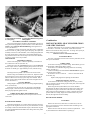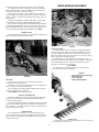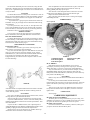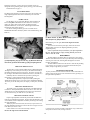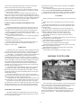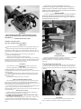
1
INDEX
INSTRUCTION MANUAL
1
Accessories
Chain Guard
Chain Saw
Circular Saw
Dual Wheels
ENGINE CARE
Extension Axles
Gang Mower
Geared Wheels
Hay Rake
Leaf Mulcher
Lubrication, Tractor
Oil Pressure Gauge
Operating Hints
Power Brush
Power Spreader
Power Take-Off
Rear Hitch
Reel Mower
Riding Sulky
Roller
Rotary Cultivator
Rotary Knife Mower
Rotary Plow
Sickle Grinder
Sickle Mower
Snowblower
Snow Plow, Blade Type
Steering Sulky
Tire Chains
Toolholder Cultivator
Tools, attaching
TRACTOR OPERATION
Trouble Shooting
24
10
10
12
15
1&4
15
8
17
24
10
1
24
6
22
22
23
23
6
24
13
17
9
15
24
13
21
21
12 & 24
24
19
2
2-6
5
THANK YOU
For your investment in Gravely Equipment. It is an investment,
for the Gravely will save you work and worry for many years.
You will gain still greater satisfaction from your powerful
Gravely if you add the tools you need for your other jobs. From time
to time we suggest you consult our catalog, or this instruction book.
You will find many attachments that will eliminate upkeep and garden
drudgery.
Your Gravely representative will be glad to demonstrate any
Gravely attachment to you any time. There is no obligation involved.
If you require parts and service, our representatives have the
facilities to handle your problems. They are specialists in Gravely
Service have the special tools and training necessary to give you the
best possible job at the most economical price.
We sincerely hope you will enjoy the use of your Gravely
Equipment for many pleasant and profitable years.
Yours sincerely,
GRAVELY TRACTORS, INC.
2
THE GRAVELY TRACTOR...
OIL BATH AIR CLEANER
Gravely Tractors are equipped with an Oil Bath Air Cleaner. Inspect
daily during operation. Empty the cleaner, and fill the cup with
Mobiloil AF (SAE 30) as required, according to directions on the Air
Cleaner.
The Gravely Tractor is a 6.6 HP Air-cooled, 4 cycle, onecylinder
Tractor. It is designed and built for the tough jobs . . . furnishes POWER
for over 30 different tools and attachments.
It will serve you long and faithfully if you take reasonable care. You
will find it is to your advantage to read these instructions carefully and
follow them faithfully. You will be rewarded by more satisfaction with
your Gravely Equipment, and fewer repair and maintenance bills.
VALVE TOP OIL
During the breaking-in period, use Mobil Upperlube mixed with the
gasoline according to the directions on the can. This will help furnish
lubrication for. the Valves during the critical run-in period.
WHO MAKES IT?
Gravely Tractors, Inc., Dunbar, West Virginia, and Gravely Tractor
Company, Southern Region. The Gravely Tractor and its Attachments are
produced in these factories which specialize in the production of Gravely
Tractors and Attachments . . . and nothing else.
BREAKING-IN LUBRICATION.-OIL CHANGES
When your Gravely Tractor is new, the Motor Oil should be changed
after the first 20 hours of work. After that, oil change depends upon
usage. A good practice is to change every 50 hours worked.
TRACTORS WITH SERIAL NUMBER M15475 and BELOW:
The Oil Drain is an Oil Drain Plug located on the bottom of the
Chassis.
TRACTORS WITH SERIAL NUMBER TV115476 and ABOVE:
The oil drain is the bottom bolt on the Axle Housing, on the left side
of the Tractor as you stand behind the Tractor at the Handles.
Care should be taken any time the Axle Housing is removed and
replaced to make sure the Nylon Plugged Drain Bolt is always
reinserted in the bottom bolt hole, and the special sealing washer is in
place.
OIL CHANGES AT RIGHT TIME IMPORTANT FOR
EQUIPMENT SATISFACTION
Changing of the Oil Filter often is another must. The Gravely Tractor
works under the dirtiest, dustiest of conditions. For long life, change the
Oil Filter at least twice a Season.
The contaminants that collect unavoidably in the oil during use are
not all removed by the oil filter. Changing oil at regular intervals (at
least every 50 hours as recommended above) is the surest way of
removing contaminants. Rubbing used oil between the fingers and color
changes are not reliable methods of determining the oil's suitability for
further use. Since some contaminants are soluble in oil, a detergent type
oil may darken rather quickly giving good evidence that it is properly
performing its function of holding deposit forming materials suspended
in the oil. It is always safer to change oil rather frequently than to try to
reduce expense by running oil too long.
This care, once or twice a season, will repay you many times over.
The Oil System is the heart of the engine .
with proper care your engine will continue to operate efficiently and
effectively. Neglect will surely cost you time and money in major
repair.
WHO SELLS AND SERVICES GRAVELY EQUIPMENT?
The Gravely Tractor and its Attachments are distributed through more
than 47 Distributing Companies. Working with these Distributing
Companies is an organization of independent Dealers. Each of these
Dealers and Distributors is fully equipped to give prompt and efficient
service-have parts in stock which means service fast . . . without waiting
on factory shipment of parts.
GUARANTEE
The Gravely Guarantee is on the Back Cover of this User Manual.
NOTE: To qualify for this guarantee, it is necessary for you to return
the card bound into this booklet to the manufacturer. Do so promptly,
for your own protection. A postage-free envelope is furnished.
FUEL
Use a good regular gasoline. We recommend Mobilgas (A Socony
Mobil Product). Tank capacity is about 1 and 3/4 gallons. DO NOT USE
HIGH TEST GASOLINE.
LUBRICATION
SUMMER:
Esso Aviation (SAE 40)
WINTER:
Temperature range from 32 to 10 use Esso
Standard (SAE 20-20W)
Temperature range from 10 and below use
Esso (SAE 10-lOW)
WINTER: Temperature range from 32° F. and below, use Mobiloil
Arctic (SAE 20) or Mobiloil Special SAE 1OW-30.
Filling the Chassis (Transmission) furnishes oil for both the Motor and
the Transmission. WARNING: Do not use Transmission Greases or Oils.
Only Motor Oils.
CHECKING OIL LEVEL
Be sure that your Tractor is setting level.
1. On some Tractors, locate the Bronze Try Cock Valve (see No. 2,
Plate 2). Remove the Wing Tee completely. Do not attempt to check oil by
merely loosening, as dirt and foreign material clog the small Try Cock
checking holes.
If OIL RUNS OUT, you have enough. If it does not, add oil until it
begins to run out the Oil Level Hole.
2. A !'4" Oil Level Plug may be found on some Tractors, at the same
location as the Bronze Try Cock Valve. Remove with a wrench or
specially punched hole in the Starter Strap Handle. Then proceed as in
paragraph 2 in "Bronze Try Cock Valve."
3. Still in the same location, a 3/4" Cadmium Plated (bright) Plug may
be found on some Tractors. Remove with a wrench and proceed as in
paragraph 2 in "Bronze Try Cock Valve."
TOO MUCH OIL IS AS BAD AS NOT ENOUGH. DO NOT ADD
MORE THAN ENOUGH OIL TO BEGIN TO OVERFLOW THROUGH
THE OIL LEVEL HOLE.
Be sure to check oil level every day of operation.
PLATE 2
(1) Clutch Adjusting Nuts, (Z) Oil Level Try Cock.
1
ATTACHMENT CLUTCH
The Attachment Clutch is actuated by a lever on the front of the
Tractor (See Plate 8).
On the Advance Casting you will see the words IN and OUT
embossed on the metal.
When the lever is over the IN, the attachment is in gear. OUT, the
attachment is out of gear.
HINT: When putting POWER ATTACHMENTS in gear, have the
High-Low Lever in Neutral. Then "slip" the clutch, using the reverse
only until you hear or feel the engine "pull down" a little. You can then
flip the attachment in gear without raking the Attachment Clutch Gear.
This Will save wear on the clutch.
CAUTION: When attaching or adjusting a POWER
ATTACHMENT, always have the Attachment Clutch Lever in the
OUT position, the Tractor Engine stopped.
GAS THROTTLE
The Gravely uses a hand-feed fuel throttle attached to the left handle.
Depressing the throttle gives more fuel, bringing it up feeds less.
GOVERNOR
The Governor is optional. It will automatically feed the fuel to the
engine according to the work-load. This saves wear on the equipment,
and makes operation of the equipment much easier.
There are two types of Governor control used on Gravely Tractors.
To operate-if yours is the "push-pull" type-simply pull the Governor
Throttle out until the Attachment operates at the speed you desire. After
this speed is obtained, the Equipment will operate at that speed no
matter how much load is put on the machine, without further attention
from you. To reduce speed, push Throttle in.
If you have the Lever type Governor control-push the Throttle Lever
down with thumb of left hand, until the Attachment reaches your
desired speed. Again the equipment will operate at that speed with no
further attention from you. To reduce speed, simply move Lever up
with thumb.
CHANGING GEARS
The Gravely Tractor gives you two forward and two reverse speeds.
As you stand at the Handles of the Tractor:
LEFT HAND Lever is gear selector, for high and low
speeds.
RIGHT HAND Lever is gear selector for forward and
reverse.
PLATE 8
NEUTRAL: Both Handles in UP
Position.
FORWARD: Right hand lever back
and down.
ATTACHING TOOLS
All Power Attachments and all others, except a few tools which may
be hitched on the rear of the Tractor, are attached by four bolts to the
front of the Tractor. (See Plate 9.)
The Attachment Clutch Lever must be in the OUT position when
attaching any tool to the front of the Tractor.
Attaching Attachments is much easier with a Gravely Tractor Stand.
This portable, inexpensive stand allows you to quickly adjust height of
Advance Casting, holds Tractor firmly for easy attachment of tools.
HIGH: Left hand lever back and
down.
LOW: left hand lever forward
and down.
CAUTION: Always keep
your hand on the Reverse
lever when you are backing
up. Then, if you slip, or get
backed into a corner, you
can throw the machine out
of gear quickly.
You may change either
lever without changing the
other.
REVERSE: Right hand lever
forward and down.
OPTIONAL ATTACHMENT CLUTCH CONTROL
An optional Attachment Clutch Control may be obtained for
greater convenience. See illustration on page 24.
PLATE 9
2
PREPARING TO START THE TRACTOR
1.
2.
3.
4.
enough momentum to run through the firing cycle twice and then carry
itself. So it will be necessary to pull hard and fast.
5. Take the spark plug out and warm until all possible moisture
is evaporated.
6. If the engine doesn't start after a few tries, and all these
precautions have been taken, check for mechanical failure. (See:
Trouble Shooting.) If you still have trouble, call your Gravely Dealer
or Distributor.
Gear Levers in Neutral Position.
Attachment Clutch Lever in OUT position.
An Attachment, or the Attachment Boss Cover and Gasket
(Part No's. L-228 & L-229) must be used on the front of the
Tractor before starting motor.
Be sure the little valve on the bottom of the Sediment Bowl
under the Fuel Tank is in the open position.
STARTING THE TRACTOR
The Gravely is equipped with a strap starter. The small hole in the
end of the leather Starting Strap slips over a pin in the pulley at the
:-ear of the Tractor. Wind the strap in the direction of the embossed
arrow. Put the Throttle down about halfway. (If you have a Governor,
put the Throttle Button halfway OUT.) Give a strong, steady pull.
Choke as needed.
See Plate 10 for the proper way to wind the strap.
PLATE 11
SELF STARTER
Now you start your Tractor as easily as you start your car! New
Gravely Electric Self-Starter means push-button starting . . . new ease
and convenience in using your Gravely Tractor.
Especially useful for cold-weather starting . . . means a start every
time!
ATTACHING
PLATE 10
COLD WEATHER STARTING
Installation Instructions are packed with Starter Kit. Starter Kit
is complete, but less Battery. Uses any standard 6 Volt Automobile or
Tractor Battery.
Remember that your Gravely Tractor is an air-cooled, one-cylinder
engine, with the spark furnished by a Magneto. If you have trouble
starting your tractor during cold weather take the following
precautions:
1. Store the Gravely in a heated building, if at all possible. If not,
then pre-heat the engine by any safe method. An Engine heater,
produced especially for the Gravely Tractor is available at low cost.
Inquire from your Dealer, or from Gravely Tractors, Inc. DO NOT
USE A BLOW-TORCH OR ANY OPEN FLAME OF ANY KIND!
BE SURE TO CHECK FOR GASOLINE LEAKS BEFORE
ATTEMPTING TO PRE-HEAT THE ENGINE.
2. Be sure you have the proper lubricants in the Tractor. (See
Lubrication, page 1.)
3. Each engine is a distinct unit like an automobile engine. The best
"Choking" method will have to be found by experimentation. As a
starter, however, try by opening the Choke. Turn over engine until it
starts, then gradually return the choke as the engine warms up.
If this doesn't work and the engine floods, pull the engine over
several times with the Choke in and the Fuel Throttle open. Then try
opening the Choke for one turn, then closing again.
4. Spin the engine. hard and fast. When the engine is warm, the
Gravely will start on the first pull. But in cold weather, the temperature
in the combustion chamber is much lower. Often the engine will fire
once, but not have
CHECK OIL PUMP
As soon as the tractor starts, check the oil pump to make sure it is
working. To do this, remove the Oil Filler Cap (See Cover) and make
sure a good steady stream is flowing.
If the oil isn't flowing, push down on the handles, tipping the
tractor back. Hold it back a few seconds, then return it to the usual
position. Check pump flow again. IF IT ISN'T OPERATING, STOP
THE TRACTOR IMMEDIATELY. Call your Dealer.
(A Gravely Oil Pressure Gauge makes this checking easy.)
STOPPING THE TRACTOR ENGINE
On the Magneto (Plate 12) there is a small clip, or button. To stop
the engine, depress this button and hold it depressed until the engine
stops.
TIRES
The recommended pressure for the Tractor tire is 20 pounds.
Sulky tires take the same. Transportation Cart tire pressure should be
30 to 35 pounds.
3
the CENTER of the Clutch. Then adjust the spring tension by
tightening or loosening the 6 bolts EVENLY so that it takes 30 to 36
pounds of pressure to make the clutch slip.
PLATE 12
ADJUSTMENTS YOU SHOULD KNOW
SPARK PLUGS
Spark Plug points should be cleaned and adjusted for clearance
occasionally. The recommended gap is .033.
VALVES
Valves can be set in the field if necessary. The clearance between
Valve Stem and Valve Plunger is .012.
TRACTORS WITH MANUFACTURING NUMBER B-7619 AND
BELOW:
To adjust Valves, turn engine of tractor over until the compression
stroke. (Both valves seated, piston top dead center.) Raise the Spring
Sleeves. You will need two wrenches, a 9/16" open end, and a 1/2"
open end. The 9/16" nut is the lock nut . . hold it with your wrench and
operate the 1/2" bolt with the other, adjusting until the clearance is correct. Lock in place with 9/16" nut.
Note: The clearance is .012 WHEN THE ENGINE IS COLD. DO
NOT ADJUST VALVES WHEN ENGINE IS WARM OR HOT.
TRACTORS WITH MANUFACTURING NUMBER B-7620 AND
ABOVE:
Remove Valve Cover Cap and use 7/16" open end wrench to adjust
Tappet clearance. This is a self locking Tappet. Clearance is the
same-.012 engine COLD.
PLATE 13
TIMING THE MODEL L ENGINE
Magneto should be set to fire 30 Degrees ahead of top dead center on
the compression stroke (which is when both valves are closed).
To accomplish the 30 degree ahead of top dead center firing, proceed
as follows:
1. Loosen Magneto Coupling bolt until the coupling moves on the
Camshaft. It may be necessary to tap gently.
2. Crank Starter Pulley until you feel the beginning of the
Compression Stroke. Remove Spark Plug, observe by eye or, more
accurately, measure to piston surface until Piston is exactly at Top
Dead Center.
3. Hold the Magneto Shaft Extension with Vise-Grip Pliers so it will
not move after taking up gear backlash by moving pliers up gently.
Rotate the Magneto Impulse (inoperative) until timing marks (line
on Coupling flange and dot on Magneto face) line up.
4. Reassemble Magneto Coupling, inserting 1 / 64th (.015) Feeler
between Fiber Block and the Coupling Flange before tightening
Magneto Coupling so you will not cramp the impulse. Be sure
timing marks are together while tightening bolt.
CLUTCHES
The Gravely uses a double-acting, cone-type Clutch. To take up for
wear, tighten the nuts on the ends of the Clutch Rods. If adjustment is
needed, your Clutch will "slip" even when locked in position. Unless
the Clutch is slipping, let the adjustment alone. (See Plate 2.)
The Gravely Clutch may have a tendency to "creep" a little
occasionally, even when in neutral. This is of no consequence and
does not mean that there is anything wrong with the Tractor or the
Clutches.
If it is absolutely necessary to adjust the Carburetor yourself, here is
the proper way:
SAFETY CLUTCH
Each Gravely Model L Attachment has a Gravely Safety Clutch,
which prevents sudden shocks from harming the attachment or tractor.
It is very important that these Clutches be adjusted correctly. If
they are too loose, the Tractor will not drive the attachment efficiently.
If too tight, it is possible that a sudden shock may injure the
transmission or the attachment.
The illustration (Plate 13) shows the proper method of field
adjustment. Place a flat bar in the driving slots of the Slip Clutch.
Hook a pair of spring scales on the bar 12" from
Find the main jet (needle valve). It is identified by having a brass T
on it. Screw the T in until it is snug-be very careful not to force it or screw
it tightly. On the cast-iron carburetor (Model No. 9995), back it out 2 1/2
full turns. On the aluminum die-cast carburetor (Model No. 0-12108), back
it out 23/4 full turns. Start the tractor. Open the throttle about half-way, or
to a fast idle. Let the tractor warm up. Then begin screwing the jet in
slowly. As soon as you hear the Motor slow down, STOP, and back the jet
out 1/4 turn.
The Air Jet is a screw with a slotted head and a spring wound around
the screw surface. Screw it all the way in,
CARBURETOR ADJUSTMENT
4
2. Remove Spark Plug and put 1/4 pint of Mobiloil 1OW (SAE
1OW) into the Cylinder. Turn over engine by hand (by twisting the
starting pulley) several times. If Engine stops suddenly during this
process, or if it turns over too easily, showing no compression, see:
TROUBLE SHOOTING under "Sticking Valves." Replace Spark Plug.
3. Fill Fuel Tank with fresh Mobilgas (Regular).
4. Pump tires up to 20 pound pressure.
5. If Oil Filter has not been replaced during the last
season, it is best to replace it now.
6. Start your Tractor in the usual manner.
TROUBLE SHOOTING
Your Gravely, like any mechanical product, is going to break
down or be out of adjustment occasionally. This section will deal with
the minor difficulties that are corrected easily.
In case of a serious breakdown, or if these suggestions do not cure
your Tractor's trouble, always call your Gravely Dealer. His mechanic
is trained in factory methods, has the special tools to repair your
equipment quickly and efficiently.
TROUBLE
Tractor Fails To Start.
Cause and Cure:
1. Out of Gasoline.
2. Not getting Fuel because the Fuel Cut-Off Valve on the
Sediment Bowl under the Fuel Tank has been turned off.
3. Engine flooded. If this is the case, the Carburetor will be wet
with gasoline. To cure, turn the Fan Pulley backwards by hand a
couple of times.
4. Spark Plug shorted out by contacting Tractor Hood. To check,
lift Hood and attempt to start the Tractor, Also, check
connections to Magneto and to Spark Plug.
5. Spark Plug fouled or wet. To cure, remove, clean or dry, reset at
.033.
6. Not getting fire from Magneto. Remove Spark Plug from
Cylinder Head and Magneto Cable. Crank Tractor, holding
Magneto Cable so the spark will jump to the Cylinder Head. If
no spark, or very weak spark (less than 3/8"), check connections.
If they are all right, Magneto is bad. Call your Dealer.
7. Stuck Valve: Occasionally you will find that suddenly-usually
overnight, you have no compression. So, of course, the tractor
won't start. No compression means that you can spin the motor
over by hand easily. When this happens, you have a Valve stuck
in the open position (Exhaust Valve). On Tractors with
manufacturing number B-9700 and above, this will be a very
rare occurrence, since the later models have a special Bronze
Valve Guide, and Valve Covers that lubricate the Valve Stem.
However, it is quickly checked by removing the Cylinder Head
and observing the action of the Valve while cranking the engine.
On Tractors with number below B-9700, follow the procedure
given below. To keep from having this difficulty in the future,
older tractors can be converted to the new style at little expense.
Remove Spark Plug and Cylinder Head. Use a light penetrating oil,
Mobiloil 1OW (SAE 1OW) mixed half and half with kerosene. Put this
on the Valve Head liberally, paying particular attention to the Valve
Stem. Then take screwdriver and insert in the slot in the top of the
Valve, and keep trying to turn the Valve as the oil works down. The
Valve will usually free itself in a few minutes, and turn freely. Remove
the screwdriver and turn the Engine over slowly BY HAND, and if the
Valve works up and down as the engine turns over, your difficulty is
solved. Replace Cylinder Head and Spark Plug and start Engine. You
may have to pull the Strap several times until the oil and kerosene burn
out, but it will start quickly.
CAUTION: It is always a good idea. after the tractor has been
idle a day or more, to try to turn the Motor over by hand (forward
and back) before you put the strap on it. Occasionally a Valve will
stick in the down position. If you try to start the motor with the
Valve stuck down, you will
until it is snug. On the cast-iron carburetor, back out two full turns. On
the aluminum die-cast carburetor, back out 1 1/2 full turns. Start the
Tractor. Then begin screwing the Air Jet in until the Motor begins to
"Buck", spit or backfire. Back out 1g turn. If Motor is still rough, back
out another 1/R.
Write for special Carburetor instructions.
FAN BELT ADJUSTMENT
At some time or another you will need to adjust the Fan Belt. A thin
wrench is helpful but not necessary.
Between the Fan Belt Pulley and the Fan Housing there is a thin,
large nut. This nut locks the Fan Pulley Shaft to the Fan Housing. The
shaft is in an elongated slot in the Fan Housing. When the nut is
loosened, this will allow you to move the Fan Pulley up or down, to
tighten or loosen the belt as needed. After the proper belt tension is
obtained, simply tighten the nut down firmly.
If you do not have a thin wrench, remove the nut that holds the Fan
Pulley in place. Then unscrew the Fan Pulley until you have sufficient
room to get an ordinary wrench in to the nut. After adjustment, screw
the Fan Pulley back in place and replace the nut.
OPERATING PRECAUTIONS
AIR CLEANER
Your Oil Bath Air Cleaner is one of the most important parts of your
Gravely Tractor. Unless it is kept cleaned out and filled with the proper
amount of oil, dust, grit and other abrasives will get into the Carburetor
and the Cylinder, wearing out the rings and often scoring your Piston
and Cylinder. This means expensive repair bills, and poor operating
efficiency.
OUR GUARANTEE WILL NOT REPLACE PARTS THAT ARE
WORN BECAUSE OF IMPROPER CARE OF THE AIR CLEANER.
FOLLOW DIRECTIONS ON THE AIR CLEANER!
NUTS AND BOLTS
You should have a regular time to go over your Tractor and tighten it
up. This is routine for any small power equipment or any large
equipment, and is necessary to prevent future difficulty.
This is especially important after purchase-when the tractor leaves the
Dealer or Distributor it is tight. But just as an automobile has to have its
1000 mile check, so a Gravely should have its "tightening up" check
after it has been run awhile.
OIL FILTER
The Gravely uses a replaceable oil filter. It is very important that
your oil filter be in good operating condition. Therefore, be sure to
change it at least twice a season, or every 150 hours of work.
CAUTION: DO NOT ATTEMPT TO CHANGE THE
CONNECTIONS IN ANY WAY.
STORING YOUR GRAVELY
Although the Gravely now has Attachments that make it a year-round
tool, many of our Users do not use the equipment in the winter.
It is important, if you are not going to use the equipment for a time, to
know how to store it properly.
1. Clean the Tractor thoroughly with kerosene and a stiff brush.
2. Store Tractor in a dry place. Jack it up by some means, usually
this can be done by blocks under the axles.
3. Drain the Crankcase, flush with kerosene and refill with new oil.
(Use a rust preventative oil if obtainable.) Operate the Engine for
two minutes to distribute the oil. Do not get the Engine hot.
4. Remove the Spark Plug and put 1/2 pint of Mobiloil 1OW (SAE
1OW) in the Cylinder. Turn over by hand several times: leave the
Piston on top dead center, and then replace the Spark Plug.
5. Drain the Fuel Tank and Carburetor.
TAKING THE TRACTOR FROM STORAGE
There are six important steps to follow if you want your tractor to
start easily and work properly:
1. Drain out any rust preventative oil, and refill with Mobiloil AF
(SAE 30).
5
LAWN EQUIPMENT
tear off the Valve Cam, and usually knock a hole in the Crankcase.
If your Tractor Engine will not turn over by hand, follow the same
procedure as outlined above until the Valve is free.
Follow the advice given in these instructions under "Valve Top Oil." It
is important enough to repeat. Use Mobil Upperlube mixed with the
gasoline according to the instructions with this oil. This will furnish
additional lubrication for the Head and Valves; and help to prevent any
Valve sticking.
HINTS ON HANDLING THE GRAVELY TRACTOR
The Gravely is a wonderful tool to work with. You have power to
spare for any ordinary-or extraordinary-lawn, garden, or field job. It
will save you many hours of drudgery, help you have a better looking
home, give you much pleasure in your home or small farm.
These few little tips on how to handle a Gravely will add to that
pleasure. Some of them will take a little practice but it will be time
well spent.
NUMBER ONE: LET THE TRACTOR DO THE WORK!
The most common mistake of a beginner with a Gravely is to try
to help the Tractor. Just remember this-the Gravely is much more
powerful than you are. Guide it don't try to manhandle it. Let the
tractor do the work! All the pushing you do is wasted effort. All the
attempts to hold back will just wear you out. So take it easy!
Stand erect behind the tractor. Stay out from between the handles.
Hold the handles in a firm grip, but don't try
to squeeze them into little pieces. Walk or ride relaxed and at
ease. The Tractor will obey your will-learn to use the gears, and to feed
the fuel as needed.
Give with the Tractor in unusual situations. Always remember the
Tractor is stronger than you-like a horse. Ride with it, and you will
always have control.
NUMBER TWO: KEEP YOUR TRACTOR TIGHTENED UP.
Have a regular time to go over the Tractor and tighten up the bolts
and nuts. When you are working, take a rest occasionally and check
your Tractor. Common sense and good care will save you money, let
your tractor do its work more efficiently, save you drudgery.
NUMBER THREE: SLIPPING THE CLUTCH.
Occasionally you will find yourself in the position that your
Tractor's ground speed (forward motion) is a little too fast to do the job
right. The tendency is to slip the Clutch. But in every case, usually by
taking a slightly smaller "bite" at the job it will not be necessary to slip
the clutch. The less you slip the Clutch the longer the Clutch will last.
NUMBER FOUR: NEVER WORK AROUND AN ATTACH
MENT WHEN THE ATTACHMENT IS IN GEAR!
As a matter of fact, the safest thing to do is to stop the Tractor
whenever you have to do anything to the power Attachments.
NUMBER FIVE: KEEP YOUR FINGERS AWAY FROM
THE FAN AND THE FAN BELT.
If you have to work around the Fan or the Fan Belt, STOP the
tractor!
NUMBER SIX: WHEN USING REVERSE, KEEP YOUR
HAND ON THE LEVER.
The Gravely is a powerful machine, and it can't think for you. If
you put the machine in reverse, and come back too fast, you may
stumble, fall, or get pinned against a wall or fence. Always slow down
when reversing, keep your hand on the lever, and take it easy. Then if
something unexpected happens, you can jerk the lever into neutral and
the Tractor will stop.
NUMBER SEVEN: DON'T BE AFRAID OF THE EQUIPMENT.
The Gravely is a tool. Like any other tool, it deserves respect, but
it is made to be used-made to help you do your lawn, garden and field
tasks. Master the equipment and you will find many pleasant hours of
relaxation ahead-time when you can be accomplishing a lot of work,
and yet have a good time doing it. There is something fascinating about
a Gravely, as you will learn. Soon you will have the same affection for
it as you have for your faithful car, your favorite gun or fishing rod.
Just remember-let the Gravely do the work!
REEL MOWER INSTRUCTIONS
By attaching the 30" Reel Mower to your Gravely Tractor, you
have one of the finest lawn mowers money can buy.
The Gravely Reel Mower is a heavy-duty mower, built to last
many years. The adjustments are simple. And with a Gravely you have
more than twice the power of the average lawn mower!
The Gravely will give you a better looking lawn because it does
not streak or scalp as much as most mowers. You will truly have a
lovely lawn if you mow with Gravely
ATTACHING
The Gravely Reel Mower (30" Center Unit) is attached to the
front of the Tractor by four bolts, as are all power attachments.
LUBRICATION
The Swivel Casting is equipped with an Alemite Fitting. This
should be given a shot of Mobilgrease MP occasionally,
PLATE 14
1. Swivel Alemite Fitting
3. Oil Filler Plug
2. Strut Casting
4. Oil Level Plug
6
to keep the Swivel lubricated and to prevent rust. (See Plate 14 for
lubrication points.)
The Gear Housing should be drained at least once a year, and new oil
put into it. To drain, remove the entire M-153 Strut Casting of the Gear
Housing.
To replace the oil, or to add oil when needed, remove the Gear
Housing Oil Plug and the Oil Level Pipe Plug. Fill the Gear Housing
with Mobilube GX-140 until the oil is level with, or begins to run out
of, the Oil Level Hole. Never use more oil than is needed to fill the Gear
Housing to the bottom of the Oil Level Plug. Too much oil will cause
overheating and consequent damage to the gears. Be sure to replace
both Plugs before you begin mowing.
The Reel Bearing Alemite fittings should be given a shot of
Mobilgrease MP as needed. This lubrication is very important, for the
grease forms a water seal around the bearing. Neglect will cause the
Reel Bearing to rust, and a repair job of replacing the bearing and
readjustment of the Reel. See Plate 15.
There are four Alemite fittings on the Spacers holding the Rollers in
their proper position. Use Mobilgrease MP in these fittings, as needed
to insure free rolling.
ADJUSTING THE HEIGHT OF CUT
Cutting height is adjusted by means of the Height Adjusting Screw
(See Plate 16), Height Adjusting Screw Nut, and the Height Adjusting
Screw Lock Nut.
REVERSE LAPPING OF THE REEL
The Reel Mower has a specially designed reverse for lapping the
Reel against the Bed Knife. This will eliminate, in some cases,
grinding the Reel. It is advisable to lap the Reel whenever the Reel
adjustment against the Bed Knife Bar is changed radically.
To lap the Reel, loosen the bolt on the front of the Gear Housing.
(Plate 16.) (Be sure tractor is stopped, attachment out of gear.) This
bolt is off center. To reverse the Reel,
PLATE 15
1. Reel Alemite Fitting 12 per unit)
PLATE 17
1. V Belt Adjustment Bolt
2. Reel Adjusting Bolt
3. Reel Adjusting Bolt Lock Nut
slowly roll the Reel back and forth with the hand, pushing the bolt to
the opposite side of the housing. This engages the reverse. When it is
engaged, tighten the bolt.
Then apply a 60 grit lapping compound to the Reel with a paint
brush with the attachment running at normal speed. (Watch your
fingers!) Allow the Reel to lap in reverse until the Reel makes good
contact with the Bed Knife Bar along its entire length.
To put the Reel back in forward gear, use the same procedure as
described above, except push the bolt to the right and lock by
tightening.
REEL ADJUSTMENT
The correct adjustment of the Reel means the difference between
a good mowing job and a poor one. To test the adjustment, use a piece
of paper at different points on the Bed Knife Bar and turn the Reel
with your hand.
To do a good job, the Reel must cut the paper evenly along the
Bed Knife Bar. Reel Blade must not contact the Bar. If the Knife cuts
the paper cleanly at each point, the Reel is in adjustment. If the Knife
does not cut the paper cleanly at all points, you must adjust the Reel.
To adjust, loosen the Locking Nut and turn the Rear Screw (See
Plate 17) either left or right. Tightening (turning to the right) will move
the Reel away from the Bed Knife Bar. Loosening (turning to the left)
will allow the Reel to press harder on the Bed Knife Bar.
For example, suppose that you are facing the Reel, and nave
tested the cut. You find that the Reel pressure is light on the left side,
heavy on the right.
Loosen the Lock Nut on the Rear Left Adjusting Screw, then
loosen the Screw slightly. Loosen the Lock Nut on the Rear Right
Adjusting Screw, and tighten the Screw slightly. Test. Repeat if
necessary. Then tighten the Lock Nut to hold the adjustment. The
Front Adjusting Screws control the tension of the Spring which holds
the Reel against the Bed Knife Bar. Adjust so the Reel has firm contact
with the Bar, cutting test paper cleanly.
INSTALLATION OF V-BELTS
To install the V-Belts, loosen the Height Adjusting Screw Lock
Nut, releasing the Height Adjusting Screw. Then turn the Height
Adjusting Screw until it releases the Reel Assembly from the Strut.
Raise the Mower slightly and swing the reel backwards (toward
the tractor) until the belts are loose on the pulley. Remove the old belts
and replace with the new belts. After
PLATE 16
1. Adjusting Screw Nut
3. Adjusting Screw Lock Nut
2. Adjusting Screw
4. Shifting Fork Bolt
(R position reverses, F position is forward)
Loosen the Height Adjusting Screw Lock Nut, and turn the
Height Adjusting Screw to the right to raise the height of cut, and to
the left to lower the height of the cut. When the adjustment suits your
requirements, lock the Height Adjusting Screw Lock Nut to hold the
Adjustment, and you are ready to mow.
7
the new belts are in place, return Reel Assembly to normal position,
replace the Height Adjusting Screw and readjust the mowing height.
ADJUSTMENT OF V-BELTS
Your mower is equipped with a special V-Belt Adjustment Bolt
(See Plate 17). The V-Belts should have one inch of play in them. That
is, without forcing, but with firm pressure on one side of the V-Belt
(halfway from each pulley), it should give one inch.
To tighten, turn the Belt Adjusting Bolt clockwise. To loosen,
turn the Belt Adjusting Bolt counter-clockwise. When tightening, if the
Belt Adjusting Bolt is turned as far as it will go and the belts do not
tighten, the belts should be replaced.
GANG MOWERS
Large mowing areas deserve the same care and treatment that you
give your smaller areas. By attaching two 25 inch Gang Mowing Units
to your GRAVELY Rotary Mower, your large lawns can be mowed in
a minimum of time. Like the Rotary Mower, they have Swivel Action
which allows them to follow the contour of the ground. They do not
depend upon traction for power-they are completely power driven
from the tractor.
With the Gang Mowing Units attached to your Reel Mower, you
mow a swath 75 inches in width-and the mowing is done cleanly and
evenly.
PLATE 19
1. Outer Drive Shaft Pulley (3") 4. Outer Cross Shaft
2. Bearing Cap Screw
5. Belt and Inner Drive Shaft Pulley
3. Bearing Cap
ATTACHING
The Gang Units are attached to the Center unit (30" Reel Mower).
1. Pivot Stud
1. Pivot
3. Leader Swivel
4. Leader Swivel Pin
PLATE 18
1. Wing Bracket Bolt
3. Belt Adjusting Screw
1. Reel Mower Swivel Casting 4. Belt Adjusting Screw Lock Nut
PLATE 20
5. Height Adjusting Screw Lock Nut
6. Height Adjusting Screw
7. Leader Thrust Collars
Loosen the Bearing Cap Screws, and pull the Outer Cross Shaft
assembly out until it is possible to insert the Inner Wing Drive Pulley
(Splined) and Belt into the opening as shown in Plate 19.
Replace the Outer Cross Shaft, through the Inner Drive Pulley,
turning slightly as needed until it engages the gears in the housing.
Replace all parts.
They come to you in three assemblies: 1. The Power Take Off, 2.
Universal Drive Assembly, 3. The Leader (attached to the Gang Unit).
ASSEMBLY OF POWER TAKE OFF
The Power Take Off for the Gang Units is assembled to the Center
Unit as shown in Plate 18.
ATTACHING LEADER
Remove the Top Tie Rod Bolt, replace with the Leader Pivot and
Leader Pivot Stud as shown in Plate 20.
Attach the Leader Swivel with the Leader Swivel Pin, as
demonstrated in Plate 20.
On a new mower, the Leader Swivel Pin may not drop easily into
place. This is caused by a protective film of paint on this pin and paint
film on inside of the holes. A quick rub with very fine emery paper
will remove the paint coating, and the pin will drop into place easily.
ATTACHING BELTS TO POWER TAKE OFF
First, remove the belts from the pulleys on the Center Unit, by the
method discussed in the "REEL. MOWER" Instructions.
Remove the outer Drive Pulley, first loosening the Allen set
screws.
8
PLATE 22
PLATE 21
1. Universal Drive Assembly 3. Locking Ring Ball Receiving Holes
2. Locking Ring
4. Wing Spider
Combination:
ROTARY MOWER -LEAF MULCHER CHAIN
SAW-CIRCULAR SAW
ATTACHING UNIVERSAL ASSEMBLY
The Universal assembly is attached to the Reel Shaft by Set Screws.
First, place the Wing Spider in position and force on the shaft until it is
seated in place against the Reel Shaft Bearing. Then tighten the set
screws. (See Plate 21.)
To attach the Universal to the Power Take Off, Grasp Locking Ring
as shown in Plate 21, pulling it back against the spring. Then place the
Assembly on the Power Take Off Shaft, so the Locking Ring Balls will
be in line with the holes on the Power Take Off Shaft. Releasing the
ring will then lock the Universal securely to the Power Take Off Shaft.
To remove, simply reverse the procedure.
ADJUSTMENTS
WING DRIVE V BELTS
Tension of the Wing Drive V Belts is adjusted by a bolt and lock
nut on the Power Take Off. (See Plate 18.)
Turning the bolt to the right increases tension, to the left decreases
tension. Proper tension is found by applying firm pressure in the center
of the belt. It should "give" approximately one inch, without forcing.
With this combination you can perform four different kinds of work.
1. cut timber, 2. clear land, 3. mow lawns, weeds and brush, and 4.
mulch leaves-all with the same power drive. To change .from job to job,
simply switch the tool you want to use!
All of these tools are used on the same drive!
ATTACHING DRIVE
The drive is attached to the front of the Tractor by four bolts, like all
other power attachments.
LUBRICATION
On the Swivel Casting is an Alemite fitting. This should be given an
occasional shot of Mobilgrease MP as needed.
On the Drive is an Oil Filler Plug (large) and an Oil Level Plug
(small). (See Plate 25.)
Remove both Plugs. Fill with Mobilube GX-140 until oil begins to
run out the Oil Level Hole.
Be careful not to use too much oil . . . when it is level with the Oil
Level Hole, stop.
Replace both plugs before operating the Attachment.
LEADERS
The Gangs must run parallel to the Center Unit for best results.
After the Gangs are assembled to the Center Unit, adjust the Leader
by loosening the set screws in the Thrust Collars. Move the Leader in
whichever direction is necessary by firm taps with a hammer. When
lined up, put the Thrust Collars flush to the Leader and tighten the Set
Screws. (See Plate 21.)
CUTTING HEIGHT
Cutting Height is adjusted by means of the Wing Height Adjusting
Screw. (See Plate 20.)
Loosen the Lock Nut, turn the screw Clockwise to INCREASE
mowing height, counter-clockwise to DECREASE mowing height.
When properly adjusted, tighten lock nut.
ADJUSTING SWIVEL ACTION
On the bottom of the Swivel Casting (Part No. A-149), is a Boss,
and you will notice that the casting is split at that point, with a large bolt
and nut through the Boss.
When using the Rotary Knife Mower, the Swivel should be
loosened until the Mower will follow the ground contour with its own
weight. When using the Circular Saw or the Chain Saw, usually you
will be using the same adjustment as a clamp, to hold the Saws in the
position desired. To clamp, simply turn the attachment to the point
desired, then tighten the bolt down firmly.
LUBRICATION, REEL ADJUSTMENTS, ETC.
All other adjustments and lubrication exactly the same as for the
Center Unit.
ROTARY KNIFE MOWER
ATTACHING
ROTARY KNIFE MOWER
Remove the other tools (Chain Saw or Circular Saw), if on the
drive, by reversing the process as described under "Attaching" in the
appropriate instructions.
Remove the Drive from the Tractor, and turn it upside down . . . that
is, the attachment Drive Shaft should .be pointing up.
The Rotary Knife Mower is a versatile mower that mows the finest
lawn grass or the toughest weeds. It has very low maintenance, because
of its simple construction and minimum of parts, and mulches cut grass
to a finely shredded material that makes lawn raking unnecessary under
normal conditions.
9
PLATE 23-A
OPTIONAL CHAIN GUARD
Under certain special conditions, a Gravely Chain Guard may be
desirable. Completely encloses front of Mower, with a chain curtain to
reduce the velocity of materials that may be thrown out
LEAF MULCHER
ATTACHING
Attach the Rotary Knife Mower to the Tractor in the same manner
as previous instructions designate.
Remove the Front and Rear Fenders. Put the Rear Fender on the
front of the Rotary Knife Mower.
Put the Leaf Guard on the Rear of the Rotary Knife Mower.
OPERATING
To operate the Leaf Mulcher, proceed as though you were
mowing. Ordinarily, normal walking speed will be
sufficient to do a good job. If using on wet, concentrated leaves, it
may be necessary to go over them twice to get all the leaves.
CAUTION
Keep hands and feet away from the attachment while in gear
and for an interval after being shut off. Be sure knives have
stopped revolving before putting hands or feet under the hood!
PLATE 23
(1) Skid and Skid Panel, (2) Front Fender, (3) Rear Fender (long
guard), 14) Hood, (5) Collars, (6) Knives (2 furnished), 17)
Attachment Drive Shaft Nut, (8) Fixed Collar, (9) Hood Attaching
bolts and bolt clips.
Find the model number on your Rotary Mower Drive. On Drives with model
numbers 185, 58-A, and 58 through 52-Remove the Bolts and Bolt Clips from the
Housing.
Set the Rotary Mower Hood in place with the Rear Fender toward the Safety
Clutch end of the Swivel Housing.
Place the Bolts and Bolt Clips in place, tighten down firmly. Bend Tangs of
Clips around Bolt Heads.
When assembling model 106 Rotary Mower-place 6 Bolts and plain t/2"
Washers through holes in Mower Hood and Gear Housing Flange, from the Knife
side of the Hood. Then place Lock Washers and Nuts on end of Bolts showing
through Gear Housing Flange. Tighten Bolts very tightly.
The Model Number of the attachment will be found on the Drive Casting.
Model numbers 52, 53, 54, 55, 56, 57, take the RO-321 Knives. (Left hand
rotation.) Model numbers 58, 58-A, 185, 106 take the RO-336 Knives. (Right
hand rotation.)
To assemble the Knives, use the collars in any order you wish. Assemble one
Knife, then the spacing washer, then the other Knife. Always be sure the
counter-bored side of the collars face the knives.
ADJUSTING HEIGHT OF CUT
The height of cut is adjusted by these Collars. The closer the Knife is to the
Housing, the higher the cut, and vice versa. By using different combinations of
the three different sized Collars, you adjust the height.
ALWAYS be sure the COUNTER-BORED sides of the Collars are FACING
THE KNIVES.
SHARPENING
The knife may be sharpened by a file, or a grindstone. Attempt to follow the
same bevel as the Knife had when you obtained it, although the exact degree of
bevel is not critical.
WARNING
Never put your feet or your hands under the Hood of the Rotary Knife
Mower while the Attachment is running, or for an interval after you shut off
the Attachment. Always make sure the knives have stopped spinning before
placing your hands or feet near the Hood.
GUARD ADJUSTMENTS
When mowing short weeds and lawn grass, the Small Fender should be in
front, and the Large Fender in back.
THESE FENDERS SHOULD ALWAYS BE IN PLACE WHENEVER
YOU ARE MOWING IN A PUBLIC PLACE, NEAR A HIGHWAY OR
BUILDINGS, WHEN PEOPLE ARE NEAR THE AREA YOU ARE MOWING.
However, when you begin mowing in very high, heavy brush, or in very
thick, tough grass of considerable height, better mowing results will be obtained
if you remove the Front Fender, leaving the front of the mower open.
WARNING: When this is done, there is danger from material being
thrown from under the mower, forward. Rocks, tin cans, steel objects should
be removed from the area, and great care exercised. NEVER MOW WITH
GUARDS REMOVED IN PUBLIC PLACE'S, OR WHERE PEOPLE OR
PROPERTY CAN BE DAMAGED BY PROJECTED MATERIAL.
PLATE 24
(1) Chain, 11) Chain Blade, (3) Bracket, (4) Guide Bar Clamp Bolts,
(5) Bracket Clamp Screw, (6) Attachment Drive Shaft, (7) Sprocket,
(8) Angle Adjustment Bolt.
CHAIN SAW
ATTACHING
To attach Chain Saw Assembly to the drive, remove the large nut on the
bottom of the Attachment Drive Shaft, and remove the three Collars.
Loosen the Bracket Clamp Bolt on the split end of the Bracket until it will
slip onto the Housing from which the Attachment Drive Shaft projects. (It is
sometimes necessary to wedge the split ends apart slightly.)
On Chain Saw Drives, Models 52 through 58, the Diameter of the housing
is 23/4". These models take the Part Number CS-101 Chain Saw Bracket. On
Models 58-A and 185, the Chain Saw Bracket part number is CS-101-1, and the
10
diameter of the housing is 31/4". The bigger diameter chain saw Bracket
(CS-101-1) can be converted for use with the Models 52 through 58 of Rotary
Mower Drive by the purchase of a Converting Collar, part number CS-331.
The lower edge of the Bracket should be lined up even with the lower edge
of the Housing. (Not the fixed collar!) Then clamp the Bracket in place by
tightening the Bracket Clamp Screw. (See Plate 20.)
Rotate the Bracket until the Guide Bar is pointing straight up. Tighten the
Bracket Clamp Bolt until the Bracket stays in place.
Loosen the Guide Bar Adjusting Screw and Clamp bolts that hold the two
sides of the Bracket together. The latter should be loosened only enough to
allow the Guide Bar to slip back and forth easily.
Put the Chain on the Guide Bar, bring it through the Bracket.
Now, insert the 1/z inch Collar on the Shaft, with the COUNTER-BORED
SIDE toward the BOTTOM of the shaft. Slip the Sprocket on the Shaft, put the
Chain around it. (NOTE: The Sprocket revolves in a counter-clockwise
direction when viewed from the end of the shaft on Models 58, 58-A. 185. On
Models 52 through 57, the shaft revolves in the clockwise direction . . . the
cutting edge of the Chain Teeth must move in the same direction.)
Then follow with the 1/4 inch Collar and the ?1a inch Collar, with the
COUNTER-BORED SIDES OF BOTH COLLARS TOWARD THE
SPROCKET. Put on the flat washer, then the nut and tighten down firmly.
After adjusting and tensioning the Chain (See Adjusting and tightening the
Chain), Rotate Clamp to proper working position and tighten the bolt to hold it
in place.
ADJUSTING AND TIGHTENING THE CHAIN
After you have the Chain in pace, tighten up the Chain by means of the
Chain Adjusting Screw. The proper tension of the Chain is very important.
When properly tensioned, the Chain will be slightly loose on the Guide Bar, but
not loose enough for the Driving Links to come out of the slots when the Chain
is grasped firmly and pulled strongly away from the Guide Bar.
Care must be taken not to get the tension too tight, or you will "burn" the
Guide Bar. (See Plate 25.)
turn the Bracket and Chain Blade to the position desired, tighten the Clamp Nut
to hold it in position.
To rotate the Drive Assembly, loosen the nut on the Boss on the Swivel
Casting. This will loosen the Swivel. Rotate the Saw Assembly to the positiondesired, then tighten the nut tightly to hold the Saw in the desired position.
CHAIN SAW OPERATING INSTRUCTIONS
HOW TO SAW
Always swing the Saw SIDEWAYS into the tree if you are felling or
notching.
IMPORTANT: Never feed the Saw into the wood by any method except
light hand pressure at the handles. DO NOT lean against the handles, or brace
your body in any way to feed the Saw into the work fast.
It is so easy to feed the Gravely Chain Saw that the tendency is to force the
Saw into the wood. If you do force the Saw, it will cause excessive wear of the
Chain and Guide Bar, resulting in unsatisfactory operation and excessive
maintenance cost. Therefore, ease the Saw into the tree slowly, letting it "feed
itself" without forcing. A properly sharpened and gauged Saw will feed itself
into the work with almost no effort on your part.
DEPTH GAUGE SETTING
One of the two "secrets" of successful Chain Saw operation is the proper
setting of the "Depth Gauges." The Depth Gauges are projections that
control the depth of bite of the Saw Chain. These are NOT factory set, and
must be filed down to correct depth before your Chain Saw will cut
satisfactorily.
A "Gaugit" is furnished with each Chain Saw. Directions for its use are also
furnished, and it is very important that these directions be studied and the
simple and easy filing down of the Depth Gauges be done before you attempt
operation of the Chain Saw.
SHARPENING THE SAW
A Chain Saw will cut well only if it is sharp. Your Gravely Dealer will
furnish you with a sharpening set that makes correct sharpening of your Chain
Saw fast and easy. The set is FREE, and is made so that filing of the correct
angle of the Tooth is carried out automatically. A sharp Saw Chain is the second
of the two "Secrets" of successful Chain Saw operation.
CAUTIONS
The Chain Saw is a specialized tool, and must have specialized care for best
results. Special Instructions for proper maintenance and sharpening of the Chain
Saw are packed with the equipment. BE SURE TO READ AND FOLLOW
THESE ILLUSTRATED DIRECTIONS.
It is possible to cut timber flush with the ground when using the Gravely
Chain Saw, and in many cases this is desirable. However, digging the Saw into
the dirt means that the soil, mixed with the lubricating oil, forms an abrasive
that soon wears the Saw Chain and the Guide Bar. You can ruin a new Saw
Chain and Guide Bar in a short time unless proper precautions are taken.
This is true of ANY Chain Saw.
We recommend that if you intend to saw much timber off even with the
ground that you purchase the Circular Saw, which is inexpensive, and make a
second cut at your leisure to get rid of the low stumps you may leave. The
Circular Saw is used on the same drive as the Chain Saw.
Lubrication of the Saw Chain is very important. Lack of lubrication will
"burn" the Guide Bar. (See Chain Saw oiling System.)
CHAIN SAW OILING SYSTEM
The Chain Saw has a separate assembly which furnishes oil to the Chain by
the operation of a thumb-plunger
PLATE 25
(I) Chain Adjusting Screw, (2) Guide Bar Clamp Bolts, (3) Angle
Adjustment Bolt, (4) Swivel Alemite Fitting, (5) Oil Filler Hole Plug,
(6) Oil Level Hole Plug, (7) Bracket Clamp Nut.
ANGLE ADJUSTMENTS
To change the position of the Chain Saw in relation to the Housing on
which the Bracket is mounted, loosen the Bracket Clamp Nut at the
split part of the BRACKET. Then
PLATE 26
11
LAWN ACCESSORIES
ATTACHING
First, install the Bracket on the Tractor Handle. Put in the Elbow Fitting,
and attach the tubing as shown.
To install clips on Handle Bolts, simply loosen the bolts, insert the slotted
end of the clips, and tighten the bolts.
Screw the male thread of the Flexible Tube into the Bracket of the Chain
Saw. Then attach the other end of the Flexible Tube to the Oil Pipe with the
straight Connector.
OPERATION
Depress the thumb lever on the Can. This supplies oil to the Chain. Use
ordinary motor oil-new or used-as lubricant. The Chain should receive a liberal
amount of oil during operation.
To disconnect, take the Flexible Tube loose from the Oil Pipe at the straight
Connector. The Oil Tank and Oil Pipe may be left on the Tractor, or taken off,
as you desire.
THE CIRCULAR SAW
PLATE 17
The Circular Saw is useful for clearing land, and cutting down small trees.
It has the big advantage of making short work of small scrub growth, saplings,
sprouts, etc., cutting them off even with the ground. This allows you to mow
over the area with your Gravely Sickle or Rotary Mower.
We do not recommend the Circular Saw for felling large trees. The Chain
Saw will do this job faster and better.
STEERING SULKY
A Gravely Steering Sulky gives you an amazing new experience in
easy, comfortable, efficient mowing.
You steer the tractor like a car by a steering wheel that gives you
quick, accurate, effortless control!
Attaching instructions are under "Rear Hitch", page 24. Dual
Wheels should always be used with the Steering Sulky.
ATTACHING
To make a Circular Saw of your Chain Saw or Rotary Knife Mower,
reverse the procedure described in the sections headed "Attaching" in the
instructions for these tools.
To attach the 18" Circular Saw Blade, put on the Collars and Blade IN
THIS ORDER: 7/8 inch Collar, 1/2 inch Collar, the 18" Circular Saw Blade,
then the 1/4 inch Collar. Put on the large nut and tighten down firmly.
Be sure that the Collars next to the Circular Saw Blade have the
COUNTER-BORED sides FACING the Saw Blade.
The cutting edge of the Circular Saw tooth must face the direction of shaft
rotation. See "Rotary Knife Mower" instructions to determine shaft rotation.
LUBRICATION
The only lubrication required is an occasional shot of Mobilgrease
MP in the Alemite fittings.
SAW GUARD
An optional Circular Saw Guard is available from your Dealer. To attach,
fit the Split Ring to the Housing, swing the Guard to the position desired, and
tighten down the two bolts and nuts. This will clamp the Guard in position.
Give Model Number of Drive, to assure proper size.
USING THE CIRCULAR SAW
The Circular Saw is fed into the work from the side the same way as the
Chain Saw, by pivoting the Tractor. Just exert pressure on the handle opposite
the work, and keep a firm pressure against the work. Do not force the Saw into
the tree . . . let it "eat" its way in gradually.
CLEARING LAND
The Circular Saw is most effective when used for land clearing operations.
The method is to put the Saw in the horizontal position, and drive the tractor
forward slowly. If you are working in very dense undergrowth, it is helpful to
swing the Blade back and forth as you move slowly forward. This will let you
cut a wide path. Your judgment will soon dictate when to stop the forward
movement and concentrate on a sprout or sapling that is too large to "drive
through."
Care should be taken not to run the Saw Blade into the ground, or against
rocks. This will, of course, quickly dull the Saw and require sharpening and
resetting.
PLATE 28
RIDING SULKY
A Gravely Riding Sulky allows you to mow comfortably while you
ride. You can cover an amazing amount of ground in a little while with
a Riding Sulky, and the Tractor is even easier to handle.
Handicapped persons often do a lot of their own mowing with the
Sulky when otherwise it would often be out of the question.
The Sulky has a comfortable spring seat, pneumatic tires. It
requires the Rear Hitch.
ATTACHING: See Rear Hitch, page 24.
SHARPENING THE SAW BLADE
We do not recommend field sharpening. Instead, you are better off to take
the Saw Blade to a professional Circular Saw Blade sharpener, or to your
Gravely Dealer. "Setting" the teeth requires special tools, and sharpening the
Saw with the correct angle also requires special equipment.
STORAGE
ADJUSTING THE SEAT
If you are going to store your Circular Saw Blade for several days or
longer, we recommend that you coat it heavily with Mobilgrease MP.
The Seat is attached to the Seat Spring by a bolt through one of
two holes in the Seat Spring. Adjustment is made
12
WEED MOWING EQUIPMENT
by attaching the Seat to whichever Bolt Hole is most comfortable.
It is sometimes necessary to "level" the Tractor when using the
Sulky on the Rear Hitch, to keep the Handles from interfering with
your knees on turns. This is done in two ways:
First: To level the Tractor, loosen the Ball Stud Lock Nuts. To
raise the handles, turn the Ball Stud clockwise. To lower the Handles,
counter-clockwise. The bottom of the stud has an opening to fit a 1/a"
Allen Wrench.
AFTER ADJUSTMENT, TIGHTEN THE BALL STUD LOCK
NUTS TIGHTLY AGAINST THE REAR HITCH FRAME.
Second: If there is still interference, the Handles may be adjusted
by loosening the Handle Bolts closest to the rear of the Tractor, and
moving the Handles upward or downward in the slots until they are at
the proper height. Then tighten the Handle Bolts down tightly.
LUBRICATION
The only lubrication required is an occasional shot of Mobilgrease
MP in the Alemite fittings on the Wheel Discs.
PLATE 30
SICKLE MOWER
The Gravely Sickle Mower Attachment is a rugged, dependable
mower that makes the toughest weed and brush mowing jobs easy. It
will mow anything that will go between the Guards. Swivel Action
allows the blade to follow the ground contour for a clean cut, and it is
Safety Clutch protected against damage.
The Sickle Mower is furnished with a 42 inch Blade. Longer
blades are available from your Dealer for special purposes. The Blades
are furnished with three-inch sections for heavy mowing. For fine
mowing, two-inch Sections are available.
ATTACHING
The Sickle Mower is attached by four bolts to the front of the
Tractor, like all other power attachments.
PLATE 31
1. Universal Housing Grease Plug
2. Drive Filler Plug
3. Oil Level Plug
4. Swivel Adjusting Bolts
PLATE 29
ROLLER
For a smooth, velvety lawn, you will need the Lawn Roller
Attachment for the Gravely Tractor.
The Roller is 32" wide, has rounded edges to prevent injury to the
lawn, and weighs 655 pounds when loaded.
The powerful Gravely easily handles the Roller and the operator,
who rides comfortably on a spring seat.
ATTACHING: See Rear Hitch, page 24.
FILLING THE ROLLER
The Roller is filled with water by removing the large Brass Plug
found on the right-hand side as you look from behind the Roller
toward the Tractor Handles.
Of course, the Roller should be rolled until the Plug is at its highest
point for the maximum weight. Have no hesitation about filling it as
full as possible . . . the Tractor has plenty of power for the job. Be sure
to replace the plug TIGHTLY.
LUBRICATION
The only lubrication required is an occasional greasing of the
Axles. Just remove the Cotter Pin, slip off the large washer and put a
generous amount of Mobilgrease MP around the Axle, put back the
washer and cotter pin.
LUBRICATION
You will find three Oil Plugs on the Sickle Mower Drive Column. See Plate
31. The Oil Plug on the Column section
13
closest to the Tractor lubricates the Universal. Remove the plug and fill about
half full of Mobilgrease MP.
Sometimes, since this Universal Joint needs attention only occasionally, it is
more convenient to remove the Safety Clutch, take out the four bolts that hold
the lower Column to the Universal Housing, and slip the Housing partly off.
Then you can put a generous application of Mobilgrease MP directly on the
Universal Joint, covering it all over with about an inch or inch and a half coating
of the Grease. Reassemble the parts, being sure to tighten firmly the large nut
that holds the Safety Clutch.
You will find two Oil Plugs on the Crank Housing section next to the Blade.
The smallest is the Oil Level Plug. To check the oil, remove this plug while the
attachment is on the Tractor. If oil runs out, you have enough. If it doesn't,
remove the large Oil Plug on the column directly above the Crank Housing and
fill until oil runs out the Oil Level Plug hole. Use MOBILUBE GX-140. Do not
continue to add oil after the oil starts to flow from the Oil Level hole.
When you fill this part of the Sickle Mower for the first time, or after
draining old oil, it will take one-half pint.
Be sure to replace ALL plugs before using the Sickle Mower.
LUBRICATING KNIFE AND BLADE
While the Sickle Mower is working, juices from weeds and grass will
furnish sufficient lubrication. However, the Knife and Bar will rust when not in
use.
To prevent this rusting, wipe the Knife and Bar with a cloth moistened with
light oil. Put on a thin coating.
If you are going to store the Sickle Mower for any length of time, we
recommend careful cleaning and an application of Mobilgrease MP to all
unpainted parts.
ADJUSTING THE CLIPS
The Clips that hold the Knife to the Bar should be checked and adjusted
frequently. If these clips are not adjusted properly, grass will foul between the
Knife and Guards and cause "bunching" or piling up of the grass and inadequate
feed-off. Also, fire grass will not be cut because the Knives will give enough so
that the grass is knocked into the space between the Knives and the Guards
instead of being sheared cleanly.
The Clips should be adjusted closely enough to hold the Knives in firm
contact with the Shear Plates on the Guards, but not tightly enough to bind. The
Knife should slide back and forth easily with the pressure of a finger and thumb.
The usual method is to knock down the Clips gradually with taps from a
light hammer.
If your mower has seen quite a bit of use, the iron in the Clips may have
"crystallized" slightly. This does not affect operation, but a sudden sharp blow
from a hammer may crack or break the Clip. So tap the Clips down lightly and
firmly.
KEEP THOSE BOLTS TIGHT
Any Sickle Mower, since it has a very fast change of lateral direction taking
place every few seconds, is subject to some vibration. The Gravely is built and
balanced carefully, and although vibration. is held to a minimum, it is not
eliminated.
For this reason, in certain critical places, special bolts with a high thread
count to the inch are used, and special locking nuts.
But in spite of these engineering precautions, the vibration will loosen bolts
and nuts after so long. Therefore, it is wise to periodically check and tighten the
bolts and nuts on the Attachment. You should check before you start a job, and in
very heavy cutting, we recommend that the bolts and nuts be checked frequently
and retightened if necessary.
CARE OF THE KNIVES
A sharp Sickle is the first requirement of any mowing job for satisfactory
results. A gapped, dull Sickle Knife will chew through coarse weeds and brush,
but you will run into trouble in fine grass, and not get a clean cut.
Sharpen your knife often. In fact, it is best to have an extra Knife around,
sharpened, so you can change quickly if you are caught in the middle of a
mowing job. That way you can keep a sharp Knife on your Sickle Mower, and
have a sharp Knife in reserve at all times.
To remove the Knife for sharpening, remove the Knife Bracket Screws and
slip the blade out either side. WHEN
YOU REPLACE THE BLADE, ALWAYS BE SURE THESE
SCREWS ARE TIGHT.
The Knife Sections should be ground at the same angle they were
originally. It is usually fairly easy to follow this angle. Your Dealer has
a hand Sickle Grinder that has a special grinding cone the right pitch for
grinding the Knives or for a small charge he will sharpen your Knives
for you.
ADJUSTING THE SWIVEL ACTION
A very important feature of the Gravely Sickle Mower is the swivel
action of the Cutter Bar. This swivel action is adjusted by means of the
two bolts on the upper (towards the tractor) part of the Crank Housing.
When these bolts are tight, the Bar is held rigid. When they are
loosened, the Bar will swivel and follow the contour of the ground.
The bolts should be adjusted tight enough so that the Bar will hold
its position until lowered, and loose enough so the Bar will tilt
according to the slope or contour of the ground.
ADJUSTING THE GUARDS
The Guards should always be kept in alignment. If one Guard gets
bent up and another down, it will not cut fine grass. Use a light hammer
and knock the Guards up or down until the Knives on the Sickle lay fiat
on the Shearing Plate of the Guards.
Always keep the Guard Bolts drawn up tight.
TROUBLE SHOOTING
1. Losing bolts and nuts.
Tighten bolts and nuts periodically.
Most people who lose bolts and nuts from the Sickle Mower are
trying to mow in high gear at a fast speed. Excessive speed will
exaggerate the vibration, and cause bolt and nuts to loosen much faster
than normal. Always mow at a normal walking speed.
2.
Bunching or piling of cut grass or weeds on the Blade . . .
also called improper feed-off of cut material.
There are several reasons for this-it may be one, or a combination.
First of all, check Guard alignment, Knife alignment, and the sharpness
of the Knife. Correct any of these conditions that are not right.
The usual cause is excessive mowing speed. It is important enough
to repeat . . . always mow at a normal walking speed.
Another cause is letting one end of the Sickle Mower drag up
already cut material. In normal operation, there is a three or four inch
space next to uncut material during a cut. But if you take a smaller
"bite" of uncut material and let one end of the Bar gather up cut
material, it will bind the Knife, and drag the material you are cutting so
it will pile up.
Another cause that is often a contributing factor is letting your
Mower get rusty and gummy. This increases the friction on the cut
material. Always keep the Bar clean of gum and rust.
The Safety Clutch may not be adjusted properly. In this case it will
hesitate during a cut, and the forward speed of the Tractor will cause
uncut material to be pulled loose and rammed in the Knives. Uncut
material will also jam the Knives unless they are sharp, especially in
fine grass. See "Adjusting Safety Clutch."
3. Excessive vibration.
Usual cause is that the Wearing Tip on the end o€ the Actuating
Lever is badly worn, or perhaps even lost. Or it may be loose due to
neglect of keeping the Wearing Tip tightly bolted to the Actuating
Lever. A badly worn bracket will also contribute to excessive vibration.
Or, again, you may be trying to mow too fast, and running the mower at
high speed.
SKIDS
Skids which fit under the Cutter Bar and raise it off the ground are
available at your Gravely Dealer's. For most of your work, they will not
be necessary. But they are handy for pasture mowing, where you want
to cut weeds out and let the grass grow, and for a few other purposes.
If you use four Skids, they are put directly under the first and fifth
Guard from either end. The Guard Bolts are
14
moved and the Skid Bolts put in the vacant holes, using the same
Guard Nuts. Adjusting spacers are furnished with each Skid, and with
these you car. regulate the height of cut. We do not recommend the use
of only two skids.
CAUTIONS
The Sickle Mower Knives are sharp. Never reach down to clear the
Mower, or do any adjusting whatsoever near the Sickle Bar, unless the
attachment is out of gear, and the Tractor stopped. Never handle the
attachment by the Guards
. . if you must move it, grasp it by the Column and one end of the
Sickle Bar. Never put your fingers between the Guards when moving
the attachment!
Try to keep out of wire, rocks, tin cans, etc. The Slip Clutch will
protect your attachment and your Tractor, but these will cause minor
nicks in the Knives, which will cut down on your mowing efficiency.
Remember to mow- at a normal walking speed.
MOWING SLOPES
You can mow a 60°l° slope with a Gravely Tractor and Sickle
Mower Attachment, when using Dual Wheels or Extension Axles.
ROTARY KNIFE MOWER
The Rotary Knife Mower can be used for weed cutting, as well as
fine lawn mowing. It will handle weeds of almost any height, and will
shred them into small pieces that in most cases will eliminate raking.
Full instructions will be found on page 11.
WEED MOWING ACCESSORIES
EXTENSION AXLES
Extension Axles are used to give a lower center of gravity, and
make working on steep slopes easy and efficient.
They serve about the same purpose as Dual Wheels. On some jobs,
where very steep slopes are mowed (for example, levees, railway
embankments, etc.), the Extension Axles and Dual Wheels both may
be used with a special length Cutter Bar on the Sickle Mower.
Equipped this way, the Tractor will mow anywhere a man can walk.
The chief advantage
Insert the Splined Axle of the Extension Axle in place of the short
Axle, lining up the Splines with the Gears inside the Tractor by
turning gradually until they slip into place.
Now insert the screws through the holes in the Exten- sion Axle
and the Tractor Axle Housing, put on the nuts and draw tight.
Replace the Wheel and the Wheel Nut.
Store your Short Axle for future use, first coating it thoroughly
with Mobilgrease MP.
LUBRICATION
None required
1. Dual Wheel Spacer
2. Rim Securing Bolt
3. Rim Securing Nut
PLATE 33
4. Spacer Securing Bolt
5. Wheel Rim
DUAL WHEELS
Dual Wheels will increase the usefulness of your Tractor,
especially if you hate any mowing to du on steep slopes. The Dual
Wheels will allow you to mow on a 60% slope without difficulty!
They are useful wherever you need traction-for example, in using
the Bulldozer Blade, mowing terraces and slopes with either the
Rotary Knife, Sickle or Reel Mowers, and when you want to haul very
heavy loads on the Hauling Cart.
ATTACHING
Remove every other one of the screws that hold the Wheel Rim to
the Tractor.
Use the long screws furnished with the Dual Wheel Spacer,
inserting them in the recessed or cut-out parts of the Spacer. Attach the
Spacer to the wheel by these long screws. (Be sure tire valve is in a
recess.)
Take out every other screw in the Wheel Rim of the second Tire,
line up the holes with the holes in the Spacer, insert the screws and
tighten clown.
LUBRICATION
None required.
PLATE 32
of the dual wheels as compared with the Extension Axles is that with
the Dual Wheels you have double the amount of driving surface in
contact with the ground.
ATTACHING
First, remove the Hub Cap from the Tractor Wheel. Then, unscrew
the large elastic stop nut that holds the Wheel.
Now block up the Tractor so the Wheels are free of the ground.
If you have a Wheel Knocker, screw it on the Axle and tap with a
hammer until the Wheel "breaks loose" from the tapered Axles. Then
take off the Wheel.
If you do not have a Wheel Knocker, insert a tapered punch or
wedge BETWEEN the Axle Housing and Wheel Hub and drive down
gradually, wedging the Wheel loose from the tapered Axles.
Remove the four cap screws from the Cap, and take off the Cap
and Oil Seal. The Axles will now slide out easily.
GARDENING EQUIPMENT
ROTARY PLOW ATTACHMENT
The Rotary Flow is a unique attachment It gives you a deep, even
seedbed in one operation. It is easy to handle. It will work new ground.
It is power-driven-does not depend upon traction to operate!
ROTARY CULTIVATOR
Used on the same drive m the new Rotary Cultivator, which gives
you power cultivation! With the Rotary Plow
15
and Rotary Cultivator, you have one power unit that carries you
through the entire gardening season-power plowing, power cultivating!
Full instructions on page 17.
ATTACHING DRIVE
The Rotary Plow attaches to the front of the tractor by four bolts. The
Angle Adjusting Bracket must also be attached by two of the four
attaching Bolts.
LUBRICATION
The Oil Plug is on top of the Gear Housing. Fill with about one
and one-half pints of Mobilube GX-140. When it is necessary to
replace oil, always drain out the old oil (by taking the Angle
Adjustment Bolt loose, on the tractor, and turning the attachment
upside down) and replace with new.
The Swivel Casting should be given an occasional shot of
MOBILGREASE MP as needed, by means of the Alemite fitting. (See
Plate 34.) ,
PLATE 35
(1) Wheel Bracket, (2) Wheel Bracket Clamp, (3) Axle Clamp, (4)
Axle Clamp Screw, (5) Depth Wheel.
If the side drag is to the right, decrease the angle towards the
horizontal.
To increase or decrease the plow angle, loosen the nut on the
Adjusting Bolt, and move the Adjusting Handle up or down,
retightening firmly.
A few experiments and you will have your plow adjusted to
the soil. Then plowing is simply walking behind your tractor
while it does the work!
DIRT SHIELD
The Dirt Shield for the Rotary Plow is optional at no extra charge.
This flat metal shield attaches to the top of the Rotary Plow Housing by
removing two of the bolts, inserting them through the two metal
brackets, and replacing.
The Dirt Shield is used to direct the "throw" of the dirt. By bending
it up or down, you can scatter or concentrate the dirt thrown by the
blades, and put it right where you want it.
PLATE 34
(1) Depth Adjusting Clip, (2) Oil Filler Plug, (3) Attach Dirt Shield by
these bolts, (4) Swivel Alemite Fitting, (5) Angle Adjusting Handle.
ADJUSTING DEPTH OF CUT
The large Pin or Clip in the Hex Shaft is the first depth adjustment.
The higher up on the shaft you insert the pin, the farther down will go
the blades and the deeper the furrow will be. The lower you insert the
Pin, the higher the blades and the shallower the furrow. (See Plate 36.)
Ordinarily the Pin is inserted in the top hole for plowing. For
transporting, it is placed in the last hole at the bottom.
The final depth adjustment (if required) is made by sliding the
Wheel Bracket Clamp Screw up or down on the slotted Wheel Bracket.
The lower you set the clamp screw, the deeper you will plow. (See Plate
35.)
PLOWING YOUR LAND
To plow your land, first run a furrow down the center of the land to be
plowed. Then turn the tractor at the end of the furrow by pivoting it, so
the right hand Depth Wheel
ADJUSTING WIDTH OF CUT
The width of cut is governed by the position of the Wheel Bracket
in relation to the Depth Wheel that rides in the furrow. The closer the
Wheel Bracket is to the Depth Wheel in the furrow, the narrower the
cut. The farther away, the wider the cut. (See Plate 35.)
ADJUSTING PLOWING ANGLE
Proper angle adjustment of the Rotary Plow makes the difference
between easy and difficult operation. The plow must be adjusted to your
soil conditions, and this adjustment is made by increasing or decreasing
the angle adjustment.
When you plow for the first time, the best way to proceed is to set
the angle adjustment at half-way in the slot. Be sure it is tight so it will
hold. Then try a furrow or two.
If there seems to be an excessive side drag to the left,
increase the angle towards the horizontal.
PLATE 36
is in the furrow you have just made. Continue this way, so that dirt is
always thrown to the center, turning at the end
16
the Snowblower, and in some cases either of the Saws. They must be
used with the Turn Plow.
The Gear Reduction Wheels slow down the forward speed of the
Tractor about half, but the attachment speed remains the same.
This means a much better job of plowing, for example, because the
Plow Blades strike the ground twice as many times per foot traveled.
of each furrow, dropping the right wheels of the Tractor and Depth
Wheels into the furrow until your plowing is completed.
If you are plowing a large area, you will soon be able to "pull" the
tractor around the corners without pivoting. On a small area, it will be
necessary to pivot each time.
This pivoting can be hard work unless you know this little trick.
When you are ready to turn, bear down on the handles until the tractor
is balanced. "Slip" your clutch gently, holding back slightly on the right
handle. The transmission will pull the tractor right around without much
effort on your part. A little practice will soon make you adept at this
maneuver, and will make your plowing still easier.
ATTACHING
Remove the Hub Cap of the Tractor Wheel. Unscrew the elastic stop
nut.
Block up the Tractor so the Wheels are at least 6 inches from the
ground.
If you have a Wheel Knocker, screw it on the Axle and tap with a
hammer until the Wheel "breaks loose" from the tapered Axles. Then
take off the Wheel.
If you do not have a Wheel Knocker, insert a tapered punch or
wedge BETWEEN the Axle Housing and Wheel Hub and drive down
gradually, wedging the Wheel loose from the tapered Axles.
Put the Pinion Gear on the Tractor Axle, with key in place.
Pack inside of the wheel with a pound or pound and a half of
Mobilgrease MP.
Slip the Wheel over the Pinion, matching the four holes in the Axle
Housing with those in the Geared Wheel.
The Wheel will only go on with the short stub fitting into one of the
1/2 moon cutouts on the Axle Housing rim.
Insert the four bolts and tighten down good and tight.
The Wheel should carry between 20 and 25 pounds of air, if using
Rubber Tired Gear Reduction Wheels.
Height adjustment is made by removing bolts in axle housing,
rotating housing, re-inserting bolts.
Note: Bottom bolt is drainplug-See "Oil Change," page 2.
PLOWING WITH STANDARD OR GEAR REDUCTION
WHEELS
Gear Reduction Wheels slow the forward speed of the tractor, but
allow the attachment speed to remain the same. This means that even
the toughest soil can be plowed easily with the Gravely Rotary Plow.
However, many soils are plowed satisfactorily with standard
wheels. Occasional jobs of plowing in very tough soil, sod, etc., can be
handled by making two plowing cuts
. one down to about three inches, then a second plowing getting the
full depth desired.
Also, the use of chains for standard wheels seems to meet the
requirements of some of our users.
Experiment, and consult your dealer. He will be glad to help you
decide, and will demonstrate the Gear Reduction Wheels at no
obligation, at your request.
OTHER USE'S
Your Rotary Plow can be useful for a number of different tasks that
you won't suspect until you become used to it. The following are a few
uses that our Users have told us about, which you may find helpful.
1. DITCHING . . The Rotary Plow, especially when equipped with a
special long Hex Shaft (available at your Dealer's) will do a very
creditable job of ditching. The procedure is the same as in plowing,
except normally only one pass is required in plowing. In ditching, make
one cut fairly shallow. Drop the plow further, and make the second cut,
and continue until the depth limit of the shaft and adjustments are
reached. Do not drop the wheels into the furrow when ditching, but
"straddle" the cut. A fairly heavy angle will also help, by throwing the
dirt neatly out of the ditch for you.
2. PLANTING TREES AND SHRUBS: If you have several small
trees and shrubs to plant, remove the Depth Wheels and Adjusting
Bracket from the front end of the Rotary Plow Attachment. Then take
the Adjusting Handle loose from the Adjusting Bracket. Turn the plow
until the shaft is vertical.
Then put the attachment in gear, spot it in the place you wish to
make your hole, and let the plow eat its way down. It will prepare a hole
just about right for evergreens, small shrubs and trees.
3. MAKING HILLS: When planting Sweet Potatoes and other crops
that require hills, it is easy to make the hills at the same time you plow.
The method is to start plowing right down the center of the space
you want the hill. Continue as in regular plowing until you have the hill
the right width. Then move over to the center of where you want the
next hill, repeat the process and so on until all the ground is prepared.
ROTARY CULTIVATOR
PLATE 37
The Gravely Rotary Cultivator attaches to the Gravely Rotary Plow
Drive, to form a power cultivator that tills and aerates the soil, giving
you power cultivation. It is particularly useful in Strawberry
cultivation, and does an excellent job in the garden.
It is not a deep tiller. The Gravely Rotary Cultivator and Rotary
Plow are the gardening twins-using the same attachment drive, you
plow and power cultivate . . . do the complete gardening job with
power!
GEAR REDUCTION WHEELS
Gear Reduction Wheels are indispensable when you are plowing
very hard ground, sod land, or Gumbo with the Rotary Plow. They are
also very useful when used with
17
ASSEMBLY
The unit consists of Hood, Drive, Tines.
To assemble Hood, fasten end plates to hood by bolts, washers and
nuts provided. Note that a washer is used both under the head of the
bolt and under the nut.
Assemble Tines to Shafts as follows. Place Cultivator Unit on a
suitable surface, with the Oil Filler Plug and Oil Level Plug side of the
Drive Housing facing you, the top of the Drive up (or away) from you.
See Plate 41 for the correct way to assemble the RIGHT HAND Tines
onto the shaft. Two sets, assembled as shown, will go on the right side,
two on the left. Note that the cutting edges, if the shafts were revolved
TOWARD you, would cut in the same direction as the shaft is being
revolved.
assembly, remove the four bolts from the front of the Rotary Plow Gear
Housing, and remove the assembly. Reinsert the bolts to prevent oil leakage.
WARNING. The bolts as used on the Rotary Plow will lock the Rotary
Plow Gear if tightened down tightly. We recommend the use of either
short bolts, or of Bolts held away from the housing by washers the distance
normally taken up by the Column Assembly.
Turn the Housing through 180°. In this position it will appear as in Plate
42. Note the position of the Alemite Fitting and the Adjusting Handle Boss on
the Column.
Remove the four bolts in the Bottom Cap, and insert the studs furnished. (If
you do not have a stud driver, two nuts may be locked together on the threads
and used to seat the studs firmly, then the mils removed.)
PLATE 38
To assemble the Tines to the Left Hand Shaft, assemble in the
same way, but put them on the shaft from right to left. Correctly
assembled, they will appear as in Plate 41.
Fasten by using the narrow spacer (Part No. RC-114), the large
washer (Part No. 412-W) and the Elastic Stop Nut (Part No. 225-N).
PLATE 40
ASSEMBLY OF THE HOOD TO ROTARY PLOW HOUSING
With the Rotary Plow in the same position as in Plate 39, fit the
Hood as shown in Plate 40, with the long angle of the Hood towards
the tractor.
ASSEMBLY OF THE ROTARY CULTIVATOR DRIVE TO
THE ROTARY PLOW
PLATE 39
PREPARING THE ROTARY PLOW
The first step in preparing the Rotary Plow to receive the Rotary
Cultivator is to remove the Adjusting Handle Assembly completely
from the Rotary Plow.
Remove the Rotor Shaft, Spider and Rotor Spade Cutter assembly.
(The Depth Wheels, Bracket, and Column Assembly may be
removed. They serve no useful purpose in the operation of the Rotary
Cultivator, unless it is your desire to operate the Unit with the Tines
"cutting against" the motion of the tractor. See operating instructions.)
To remove this
PLATE 41
Now insert the protruding shaft of the Rotary Cultivator Drive into
the Rotary Plow Housing, with the Oil Filler and Oil Level Plugs as
shown in Plate 41. Using the elastic stop nuts, fasten drive firmly,
making sure the Cap and Hood are properly seated. A Universal joint
on a "speed handle" wrench is most convenient for doing this
fastening job.
18
downward. With the Tines revolving in the same direction as the
Tractor Wheels, depth is controlled generally by the design of the
Cultivator, and will cultivate to about a three inch depth.
To get slightly deeper cultivation, upward pressure on the Tractor
Handles is necessary, conversely, to get less depth, slight downward
pressure on the Tractor Handles.
A smooth seedbed without tractor wheel marks is obtained by the
use of reverse (With the Tines Revolving in the same direction as the
tractor wheels when the equipment is moving forward). This is an
advantage in the preparation of lawn seedbeds, etc. With this
arrangement, it is possible to cultivate right up to a wall, for example,
then by backing away to leave a smooth, unmarked seedbed.
TINE DIRECTION of travel also controls the depth to some extent.
If you wish to obtain greater depth as a general rule, we recommend that
you assemble the Rotary Cultivator so the Tines revolve in the opposite
direction to wheel rotation when moving forward. This is done by
rotating the Rotary Cultivator Assembly through 180 degrees before
attaching. In this case, it is usually necessary to use the Rotary Plow
Depth Adjusting Wheel Assembly, to prevent the Cultivator from
"digging in" and stalling the tractor.
HOOD MANIPULATION will give you added convenience. When
you are cultivating a crop such as corn, which is generally cultivated in
such a manner as to throw some dirt around the plants, removal of the
End Plates from the Rotary Cultivator Hood will cultivate the center,
and throw a very satisfactory ridge of dirt around the plant roots.
In all other cases, such as the cultivation of bushy crops, the End
Plates should be in place to prevent tearing or damage to the plants.
NOTE: The Rotary Cultivator is designed to be a Cultivator. It is not
recommended as a tool to prepare new ground for planting. New ground
should be prepared with the Gravely Rotary Plow.
Now simply rotate the unit until it assumes the position as shown in Plate
42. In this position, the blades are cutting in the same direction as the Tractor
wheels are turning, which is the recommended method for most work.
Fill Both Rotary Plow and Rotary Cultivator Drives with oil. See
"Lubrication."
PLATE 42
ADJUSTING BRACKET
See Plate 43. The Rotary Cultivator, for best results, should have
its long axis parallel with the Tractor Axles.
TOOL CULTIVATING
You plow your ground only once or twice a season, but you
cultivate many times. The Gravely Cultivator will save you many hours
of hard, back-breaking hand work-make gardening a real pleasure by
removing the drudgery!
The Gravely Cultivator uses all Cultivating Tools interchangeably
on the same Toolholder. It is quick and easy to adjust to cultivate from
eight to 30 inches . . . wider cultivation is possible by the purchase of
extra Parallel Bars.
PLATE 44
PLATE 43
Adjust until this condition is present, then lock in place by the
Adjusting Bracket, attached as shown.
SPACERS with the assembly are to be used when the Rotary
Cultivator is removed from the Rotary Plow. The small cylinders are
used over the studs, held in place by the stud nuts.
LUBRICATION
There are two pipe plugs on the front of the Rotary Cultivator
Housing. The large plug is an oil filler plug, the small plug is the oil
level plug. We recommend Mobilube GX 140 or GX 90. Fill until the
oil begins to run out the level hole, reinsert plugs. A strip of paper
folded to make a trough will be helpful in filling. Note that the unit
should be setting level when measuring oil level.
OPERATING HINTS
CULTIVATING DEPTH is obtained and controlled by light
pressure on the Tractor Handles, either upward or
ATTACHING THE TOOLHOLDER
The Gravely Cultivator can be attached to either the front or rear of the
Tractor. Most people prefer the front, since the tools are all easily visible as you
work, and control of the Tools is easy by slight pressure on the handles.
To attach to the front, simply bolt the End Casting to the front of the
Tractor, in the same manner as all front hitch attachments, using the four bolts
furnished.
ATTACHING THE SHANKS AND TOOLS
The Shanks are inserted in the Shank Holders from the bottom. First, loosen
the hexagon head cap screw in the side until the Shank slips easily into place.
Move the Shank
19
CULTIVATING TOOLS
All Tools Used on the Same Toolholder
up or down until it meets your requirements, then tighten the cap screw
until the Shank is held firmly.
There are five Shank Holders already attached to the Cultivator in
the proper positions. These may be moved, if desired, although this is
seldom necessary. Additional Shank Holders may be purchased and
attached to suit your needs, if desired.
The Tools are divided into two classes-those that require the
"One-Hole" shank, and those that require the "Two-Hole" Shank. All
Cultivating Tools except the Furrowers, Hillers, Shovel Steel and
Turning Shovel require the "One-Hole" Shank.
To attach to the Shanks, simply bolt in place with the bolts and nuts
provided.
Changing from one tool to another only requires the switching of
the Tools on the Shanks, unless you need a "Two-Hole" Shank where
you have a "One-Hole" on the attachment. In that case change the
Shanks also.
ADJUSTMENTS
Depth Wheels are part of the Cultivator, whether used on the front
or rear of the Tractor. They are used to set the depth the cultivating
tools penetrate the ground.
With the Depth Wheels toward you turning the Handwheel to the
right will give deeper cultivation; to the left, shallower cultivation.
Usually the Depth Wheels are all the adjustment you need.
However, if necessary, you can adjust the Shanks in the Shank Holders
up or down to meet your requirements.
PLATE 46
SWEEP AND HOE SET-UP
uses an improved Sweep in the center
and a right and left Gravely Hoe on
either side. The Sweep may be
obtained in 8, 10, 12 and 18-inch
sizes. The Sweep clears the center of
weeds and trash, and the special
Gravely Hoes eliminate the majority
of hand work close to the plants.
PLATE 47
7 STEEL V SET-UP uses one Depth
Adjusting Wheel with the parallel bars
arranged to form a V. Depth is
obtained by a single adjustment of the
Depth Wheel. The cultivator will
follow the contour of the ground
closely, and the last two steels shield
foliage and vine crops so that they will
not be bruised by the wheels.
PARALLEL BARS
The Parallel Bars can be adjusted in several different ways,
depending upon the task. Usually it is necessary to disassemble the
Parallel Bars from the Depth Wheels to make these different set-ups.
OPERATING HINTS
HOW TO CULTIVATE
Cultivating depth and how close to plants to cultivate are individual
problems and preferences. However, there are certain tips that may help
you. You can set the Shanks individually, for example, so your
Cultivator will be going deep in the center, and barely stirring the dirt
next to the plants. This will save a lot of hand hoeing, and will not
damage the plants when done with care.
Of course, you must plant your rows wide enough to accommodate the
Tractor when you intend to use the Cultivator. The normal row width is
about 32-36 inches. Wider rows should be used for plants that spread
widely, unless you intend to shield the cultivator so you won't damage
the plants.
Occasionally a User tells us that he is not getting good results in hard
ground, or very stony ground. The Cultivator will have a tendency to
bounce up when it hits an obstruction. You can eliminate this very
simply and inexpensively by filling a cloth or burlap bag with about 50
pounds of sand and laying it on the Toolholder. This will hold the
Toolholder down, and does not make any appreciable difference in the
handling of the Tractor.
Incidentally, the Cultivator is very good for stirring deep litter in
brooder houses.
PLATE 48
5 STEEL SET-UP is the standard
arrangement, uses 11/4" steels.
Extra steels and shanks may be
purchased. The picture, Plate 44,
on page 19 shows the method of
arrangement when seven steels are
used. Steels are available in 11/4",
13/4", and 21/4" sizes. All
cultivating tools are used on the
same toolholder, are
interchangeable.
REAR CULTIVATOR
Many of our Users prefer
the Rear Cultivator, because
w h e n used on the rear of the
Tractor, the cultivator loosens
the dirt previously p a c k e d
down slightly by the wheels.
Set-up of tools, and
adjustments for depth are the
same as shown for the Front
Cultivator.
Rear Hitch required.
PLATE 50
6 - I N C H HILLER SET-UP
uses right and left hillers, can be used
for closing rows as well as hilling.
They throw dirt away from or around
the plants, as you desire. You can use
a furrower in the center at the same
time, bringing the dirt from the center
of the row to the hillers which in turn
heap it around the plants.
PLATE 45
20
PLATE 49
DISC HARROW The Rear Disc
Harrow is used mostly for cultivation
since the Gravely Rotary Plow gives a
perfect seedbed without any type of
harrowing or drag ging. The Disc
Harrow requires the Rear Hitch. It is
attached as shown. An occasional
squirt of Mobiloil on the Axle is the
only lubrication required. Pitch of the
Discs is adjusted by releasing the
Clamp Screw, and adjusting the pitch
of the discs to your requirements.
PLATE 51
FURROWERS are available in 10 or
12-inch sizes, may be used front or
rear to lay off rows for planting. Many
users also find it a good tool for
digging potatoes. For smaller furrows,
seven-inch shovel steels are available.
These are very handy for laying off
small seed crops and can be used for
center row cultivation.
An optional set of Casters is available for the Gravely
Snowblower, giving greater maneuverability. Also, by being able to
adjust the height, it is possible to use the Snowblower on bluestone
and gravel drives, minimizing the danger of picking up loose material
and throwing it through the Blower.
TRAVEL SPEED
To remove a maximum amount of snow, the operator should keep
the machine with full engine load at all times. This means that the
forward speed should be shifted from low to high gear as required by
the depth and density of the snow.
PLATE 52
1. Discharge Spout Clamp Wheel. 2. Discharge Spout. 3. Gear
Housing. 4. Pillow Block Screw-remove this to lubricate Pillow
Block Bearing
SNOWBLOWER INSTRUCTIONS
OPERATING INSTRUCTIONS
GRAVELY SNOWBLOWER ATTACHMENT
LUBRICATION
On the Gear Housing of the Snowblower are two pipe plugs, one large, one
small.
Remove both plugs. Fill the Gear Housing through the large hole with
Mobilube GX-90 until it begins to run out the small hole, which is the oil level.
Avoid putting in more Mobilube than is required to fill to the level of this level
plug.
There is an Alemite fitting on the swivel housing. This requires an
occasional shot of Mobilgrease MP.
The pillow block bearing requires a few drops of oil as
needed. Remove the small plug on the top of the bearing with a screwdriver,
and squirt each bearing with a few drops of motor oil. The amount of lubrication
required will vary according to your use. However, usually these bearings will
only require lubrication two or three times a season.
PLATE 52-A
POWER SPREADER
The Gravely Power Spreader (above) spreads a width from 4 to 1.2 feet and
a length of 1,050 feet in one loading. It spreads salt, sand or other
snow-removal substances, as well as granular fertilizer. Write for special
instructions.
48-INCH SNOW PLOW, BLADE TYPE
The Gravely Blade Type Snow Plow will clear the average sidewalk in one
sweep, the driveway in two. It will move snow as deep as 18 inches, deriving
its efficiency from its design-the blade does not push the snow, it ROLLS it out
of the way.
ATTACHING
The Snowblower is attached to the front of the Tractor with four bolts.
ADJUSTING
The Spout is adjustable to any angle within practical working limits, by
loosening a Handwheel and small clamp. To operate, STOP THE
ATTACHMENT by throwing out the Attachment Clutch Lever. Then loosen the
Handwheel slightly, until the Fan Housing will turn. Adjust it to the angle you desire, then
tighten the Handwheel down against the Clamp to hold the Discharge Spout in
the choosen position.
The Skids are removable by the use of a screwdriver.
MOVING VERY DEEP, HEAVY SNOW
We recommend that where you anticipate many hour of operation in deep,
heavy snows, you purchase Gravely Geared Wheels. These wheels slow the
forward speed of the Tractor one-half, while the Attachment remains at the same
speed. This will give you much more efficient action, and
more power for the wet snows. The only other method of obtaining the same
results is to "slip" the Clutch. This works for awhile but-as in an
automobile-Clutch slipping will soon cause excessive wear on the Clutches, and
require replacement.
HINTS AND CAUTIONS
NEVER attempt to kick, adjust or tinker with the Reel, Fan Housing, or
Discharge Spout while the attachment is in operation.
WARNING-NEVER PUT HANDS IN DISCHARGE SPOUT WHEN
ATTACHMENT IS IN OPERATION.
BE CAUTIOUS when operating on gravel or rock surfaces. If a heavy rock
is carried to the fan it will be expelled with enough force to hurt a person
standing in the path of snow discharge, or break windows in automobiles and
homes.
PLATE 53
ATTACHING
The Snow Plow is attached to the front of the Tractor by means of four
bolts, in exactly the same manner as all other front hitch Attachments.
21
LUBRICATION
The Gravely Power Brush is a useful tool for cleaning parking lots,
drives, sidewalks, and other areas where power sweeping is necessary.
The Brush is also useful for sweeping of light snowsit will handle
snows up to about six inches deep, brushing clean to the pavement
unless there is an ice-skim under the snow.
ATTACHING
The Power Brush is attached to the front of the Tractor by four
bolts, in the same manner as all front hitch Attachments.
LUBRICATION
On the drive of the Power Brush next to the Tractor you will see
either a Cup or an Alemite fitting. This lubricates the Swivel and should
be given a shot of Mobilgrease MP as needed.
On the section of the drive next to the Brush is a large Oil Filler
Plug. The drive should always contain enough Mobilube GX-140 so
that the Gears will dip halfway in the oil. Of course, the attachment
should be level when this checking is done. You can determine if the
attachment needs oil by removing the Oil Filler Plug and looking down
into the gears through the Oil Filler Hole.
No other lubrication is necessary except an occasional squirt of
motor oil on the Chains.
ADJUSTMENTS
CHAIN DRIVE adjustments are made by removing a half link when the
Chain has been driving long enough to "stretch." This usually takes
several months of use.
BRUSH CONTACT is adjusted by the Brush Adjusting Bolts. (See
Plate 54). Put the Brush in contact with the floor by lifting the Contact
Lever up. Then turn the Bolts until the tension desired is obtained.
The proper tension for the Brush is something that must be learned by
trial. It must have enough pressure to sweep clean. It is best to adjust
downward gradually until the correct pressure is obtained. Too much
pressure will cause the brushes to wear out prematurely.
REVERSING OR CHANGING BRUSH STRIPS
If you find that the Brushes have worn more on one side than
another, it is time to reverse the Brushes in the Brush Spiders.
Reversing or changing a Strip involves the same operation-merely
loosen the bolts that hold the Wedges in the Spider and remove the
Strip. Reverse it or insert a new one, put the Wedges in place and
tighten down the bolt. Adjust to the proper tension by the procedure
described in "Brush Contact."
None required.
ADJUSTMENTS
The Gravely Blade Type Snow Plow is adjustable to throw the snow to the
left, right, or straight ahead.
This is done by simply removing the large "T" (Adjusting Bolt and Handle)
and swinging the Blade to the position desired, lining up the proper hole in the
Bracket with the hole in the Swivel, and dropping the "T" in place to hold it.
The Wearing Strip on the bottom of the Blade will eventually need
replacement. All you do is remove the screws that hold it in place, replace the
old Strip with a new one, and reinsert and tighten down the screws.
Skids for the Snow Plow are available from your Dealer. They are installed
by removing the end screws from the Wearing Strip, and inserting the long
screws furnished with the Skid. Then slip the Skid on the screw from the back
of the blade, with the long side down and parallel to the ground, and fasten
tightly with the tilt.
OPERATION
SNOW REMOVAL
Chains available from your Gravely Representative are always helpful,
especially on icy pavement.
Skids are useful in two places . . . where you are working on concrete
pavement where one section is higher than another, forming an edge that will
catch the plow as you go along, and on gravel or bluestone drives where you
want to remove the snow but not the drive.
BULLDOZING
The Blade comes in handy for many other uses other than removing snows.
You can grade loose dirt, for example, and a set of Dual Wheels (described on
page 15) will help you get the maximum amount of work from the Blade.
Many dairy farmers and cattle farmers use the blade for cleaning up the
concrete holding pens next to the milking parlor. Some even take the tractor
right inside the barn and clean the barn interiors with the Blade.
Poultry Farmers have also found the Blade useful for clean-up work in
brooder houses. The Tractor will go through most doors, and once inside can
make short work of cleaning out dirty litter and droppings.
Motels, Parking Lots, Hotels, and Drive-In Theatres with gravel drives and
parking areas use the Blade in reverse to level the drive material. By backing up
the tractor, the Blade smooths out the humps and dug-out places into a level
surface again.
Landscapers find the Rotary Plow/Rotary Cultivator and the Blade Type
Snow Plow a good combination for lawn preparation. The lawn is plowed first,
then the Bulldozer is used to terrace or grade, finally going over the area to be
seeded IN REVERSE, with the blade following the Tractor. This gives a very
even, smooth seedbed properly prepared for lawn seeding. In some cases, the
lawn is seeded, then the Blade is used again in the same manner. This sets the
seeds at about the right depth for good germination.
Extra Brush Strips are available from your dealer.
TRANSPORTING THE BRUSH
To save unnecessary wear on the Brush, a Brush Contact Lever is
provided which, when it is in the down position, will carry the Brush
above floor level. When the Lever is pulled up, it will contact the Brush
to the Floor.
You will greatly increase Brush life if you wet down the Brushes
before use, and keep them wet during prolonged use
POWER BRUSH
1. Brush Contact Lever
2. Oil Filler Plug
PLATE 54
3. Brush Tension Adjusting Bolts
4. Swivel Grease Cup
PLATE 55
HAULING CART
There are always odd jobs of hauling to be done . . . and the Gravely
Hauling Cart will handle a thousand pound load!
22
The Cart attaches to the rear of the Tractor, has a Seat on which you can
ride while hauling.
Cart sides are removable, and stakes can be put in their place for hauling
bulky materials, such as hay. The Cart is equipped with a releasing Latch that
dumps the Cart with no effort on your part, and pneumatic tires.
ATTACHING
The Cart requires the Rear Hitch. For attaching Instructions, see next page.
LUBRICATION
The only lubrication required is an occasional shot of Mobilgrease MP in
the Alemite Fitting on each Wheel Disc.
REAR HITCH
The Rear Hitch is required for the Riding Sulky, Hauling Cart, Hay
Rake, Disc Harrow, Rear Cultivator, and Turnplow.
POWER TAKE-OFF
PLATE 57
ATTACHING
First, attach the Braces loosely to the Frame of the Hitch, with the
short twist down. (See Plate 57.)
Remove the second bolt from the bottom of the Chassis Casting,
on both sides.
Slip the Frame in place, with the Steel Strip on the extreme end of
the Frame on top.
Insert the two 1/2" x 11/4" bolts and tighten. (These are furnished
with the Rear Hitch.)
Remove the nuts from the L-224 Bracket, slip the Braces on,
replace the nuts. (On Tractors with serial numbers less than 80,000, the
length of the stud in the L-224 Bracket may be inadequate if both the
Rear Hitch Brace and the Governor Bracket is mounted. In this case,
order a new L-224 Bracket from your dealer.)
Now place the large nut on the Ball Stud, running nut up to the end
of the threads. Screw the Ball Stud into the threaded hole on the Rear
Hitch Cross Piece. Place the second nut on the threads and lock tightly
to the frame, with the Ball towards the ground. (The bottom of the Ball
Stud has an opening to fit a 1/.1" Allen Wrench.)
Run the Ball Stud Lock Nuts TIGHTLY against the Box Frame. IT
IS IMPORTANT TO TIGHTEN THE NUTS SECURELY AGAINST
THE REAR HITCH FRAME BECAUSE THE NUTS, INSTEAD OF
THE THREADED STUD, MUST TAKE THE THRUST. UNLESS
YOU TIGHTEN BOTH NUTS YOU MAY STRIP THE THREADS
IN THE REAR HITCH FRAME.
To Level the Tractor, after an attachment is in place, loosen the
Ball Stud Lock Nuts. To raise the handles, turn the Ball Stud
clockwise. To lower the handles, counterclockwise.
PLATE 56
The Gravely Power Take-Off is useful for running any equipment that gets
its power from a belt, and that requires not more than 3.5 Horsepower to operate
it.
ATTACHING
The Gravely Power Take Off is attached to the Tractor by four bolts, as are
all power attachments. However, the Stand, at your option, may be bolted on at
the same time as you attach the Power Take Off to the Tractor. (See Plate 56.)
The standard bolts will hold the attachment, but we recommend that when
using the stand you use a bolt 1/4 inch longer in length. These are available from
your dealer.
If you have a job that requires the use of a Power Take Off frequently,
sometimes it is a good idea to bolt the Stand in the proper place for the job. Then
you can simply run the tractor onto the Power Take Off, tighten down the bolts
and be ready for operation.
LUBRICATION
None required.
BELT ALIGNMENT
Always be sure that the belts are in alignment during operation. Proper
tension is a matter of trial for the individual task to be performed. The same
applies to the size of Pulley needed.
CAUTION
Do not run engine wide open on any belt job, for any extended period of
time.
HOW TO FIGURE PULLEY SIZE AND RPM
Sometimes you will have to figure how to use the Power Take Off with a
piece of equipment that has a certain speed at which it should operate.
To find out which size Pulley to use, and what RPM will be generated, AT
NORMAL WORKING SPEED-(throttle 2/3 down) use the table below.
P.T.O.
Pulley
Dia.
4"
6"
12"
IMPORTANT! Attachment Boss Cover, or Toolholder
Frame must be used on the front of the Tractor when using a
Rear Attachment!
DRIVE PULLEY
LUBRICATION
4"
5"
6”
7"
8"
9"
10"
11° 12"
1200 960 800 685 600 533 480 436 400
1800 1440 1200 1028 900 800 720 654 600
3600 2880 2400 2057 1800 1600 1440 1309 1200
None required.
INDIVIDUAL ATTACHMENT INSTRUCTIONS
LAWN ROLLER, TRANSPORTATION CART
(Same methods apply to both)
The above speeds are based on P.T.O. speed of 1200 R.P.M. in
high gear with engine operating at 7400 R.P.M. (Throttle 2/,3
down.)
ATTACHING
Assemble the Roller Rest Socket by slipping the Roller over the small
end, and securing it in place with the Retaining Ring.
23
are packed with the attachment. If additional instructions are needed,
they are available on request.
UNLOADED, Place Socket on Ball Stud, with the Roller end of
the Roller Rest Socket resting on the Rear Hitch Bottom Cross Piece.
While holding the Roller Rest Socket in this position, bring the hollow
Draw Bar over the end of the Roller Rest Socket, and drop the Draw
Bar Pin in place.
ACCESSORIES FOR YOUR GRAVELY
PLATE 58-A
PLATE 58
LOADED, Attach the Roller Rest Socket to the Draw Bar. Bring
the Tractor with Rear Hitch to the attachment, then stand the Tractor
on its "nose." Guide the Roller of the Roller Rest Socket into position
on the Rear Hitch Bottom Cross Piece. Pull Tractor down to normal
position, guiding the Ball Stud into the Socket.
Level Tractor, if necessary, according to Rear Hitch Instructions.
HAY RAKE
Use "LOADED" method under Lawn Roller, Transportation Cart.
STEERING SULKY
Bring the Steering Sulky Yoke over the outside of the Rear Hitch,
lining up the holes in the Yoke with the holes in the SIDE of the Rear
Hitch.
Attach with Shoulder Bolts and Elastic Stop Nuts and run down
tightly. Yoke will be stable and won't work loose.
The Adjustment of the Wire Cable is critical for good operation.
With the wheels in line with the frame member be sure the tension is
equal on each strand of the Wire Cable. This is adjusted by the nuts on
the ends of the threaded portion of the wire cable.
Check this tension at reasonable intervals, and keep it tight for best
results.
Dual Wheels should always be used on the tractor when using the
Steering Sulky.
RIDING SULKY
The Riding Sulky is ordinarily use:; with another attachment on the
front, in which case the Split Socket furnished with the Rear Hitch is
used.
Place the Split Socket on the Rear Hitch Ball Stud, pull the Draw
Bar of the Sulky over the end of the Split Sockets, and drop the Draw
Bar Pin through the holes in the Draw Bar and the Split Socket.
SPECIAL INSTRUCTIONS AVAILABLE
Some Gravely attachments arc not covered by the instructions in
this manual. In most cases, special instructions
ATTACHMENT CLUTCH CONTROL
You engage and disengage your Attachments much easier with the
Gravely Attachment Clutch Control. ']'fit' Control, mounted along the
left Tractor Handle, allows you to engage and disengage the
Attachments without leaving your position behind the Tractor.
The Attachment Clutch Control Kit can be installed quickly and
easily in a few minutes
GOVERNOR
The Gravely Governor will make much of your oper ation easier
by feeding the fuel as required, -automatically! It's like having an
extra hand-especially useful in plowing and mowing where the load on
the Engine varies so rapid l \ .
In addition to convenience, the Governor is good for your
Tractor-it prevents racing of the Motor, always sees automatically-that
the correct amount of fuel is being fed to handle the load!
OIL PRESSURE GAUGE
The Oil Pressure Gauge is an optional attachm nt that soon pays
for itself in more convenient operation. instead of lifting off the Oil
Filler Cap to check the ()it pump. simply. check the Gauge!
TRACTOR COVER
The Gravely Tractor Cover is specifically designed to protect your
tractor from weather, lire and water damage, and tampering. It is built
to last . . . constructed of fire-proof, mildew-proof, waterproof, heavy
duck with reinforced grow
mets, edges and cutouts.
The Cover fits snugly down over the handles and reaches entirely
to the floor or the ground.
TIRE CHAINS
You will need Chains when using your Tractor fur Snow removal,
especially when there is a thin glaze of ice under the snow. The
Gravely Chains are easily put on or taken off, and will give you the
extra traction yoti need.
SICKLE GRINDER
The Gravely Sickle Grinder is a necessity it' you d0 much mowing
with your Sickle Mower. The Grinder Mines equipped with a 3" Cone
the correct bevel to sharpen your 3` Sickle Knives exactly right . . . and
sharp knives arc necessary for efficient mowing.
2" cones are also available for 2" sections. Specify which is desired
when you order.
Full instructions for use arc packed \c ith each Grinder.
TRACTOR STAND
The Tractor Stand makes changing attachments even easier. Quickly
adjustable height, it supports the tractor while you change attachments.
Ask your Gravely representative about the Tractor Stand.
HANDLE STOP SWITCH
An optional, inexpensive Handle Stop Switch lets you stop the
motor by flipping a lever oft Hie handle Inexpensive easy to install
yourself'.
24
USE-MULTIPLIER TOOLS
SEEDER SPREADER
For your convenience, the Gravely Company
has made arrangements with other reputable
manufacturers for furnishing additional tools to
help you make the most of Gravely Equipment.
Some of these tools are illustrated on this page.
The "Use-Multiplier" attachments have been
carefully adapted to Gravely Equipment. They are
guaranteed by their manufacturers under their usual
guarantee.
These attachments will expand and multi- the
number of jobs that Gravely can make easier, do
better for you.
Let us send you our booklet, the "Gravely Use
-Multiplier," FREE, without obligation. 1• ull
information, specifications, prices for each of these
attachments-and others-are included.
A post card will do-or ask your Gravely Dealer
for your copy.
POWER VS. DRUDGERY
GENERATOR
From time to time new attachments and
improvements are made in Gravely Equipment. We
suggest you keep your Gravely catalog "Power Vs.
Drudgery" - handy, and look it over from time to
time. You will find other Attachments that will
make your jobs faster, easier-and get the job done
better!
BLITZ FOGGER
15 GALLON SPRAYER
25
UTILITY PUMP
Guarantee
The GRAVELY Tractor and Attachments are guaranteed to be free from defective
material and workmanship for a period of ninety (90) days and all defective parts will be replaced
without charge, provided such parts are returned to our factory, transportation charges prepaid, and
in our opinion after inspection are defective, and have not been damaged through neglect of
operation.
IMPORTANT
This is your guarantee, but it is not valid or effective unless within seven days after delivery of your
equipment you complete the "Guarantee Registration Card" and mail it to
GRAVELY TRACTORS, INC.
Dunbar, West Virginia
Be Sure to Mail Your
Guarantee Registration Cord!
Parts and Price Lists Available
on Request
MS-38-I
25M-1960
26
Printed in
United States of America