1
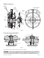
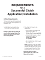
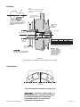
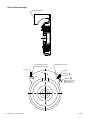
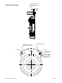
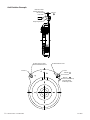
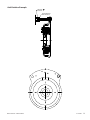
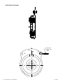
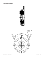
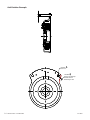
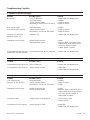
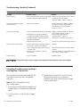
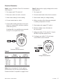
Residential, TG-2000, and
Commercial MagStop® Clutch/Brake
P-1177
819-0457
Installation & Operation
2
Warner Electric • 800-825-9050
819-0457
Contents
This guide applies to Warner Electric MagStop®
Terminology . . . . . . . . . . . . . . . . . . . . . . . . . . . 4
MagStop® Components . . . . . . . . . . . . . . . . . . 5
Mounting Requirements . . . . . . . . . . . . . . . . 6-7
Anti-Rotation Examples . . . . . . . . . . . . . . . 8-14
Troubleshooting Checklist . . . . . . . . . . . . 15-16
Electrical Evaluation. . . . . . . . . . . . . . . . . . . . 17
clutches and clutch/brakes used on power
equipment.
Residential, TG-2000, and Commercial
MagStops are available in a range of torque
capacities. The MagStop® name comes from
the permanent magnet brake (magnetic stopping) rather than conventional spring activated
mechanical brakes. In addition to these general
procedures, any applicable OEM general
and safety procedures must also be followed.
Failure to follow these
instructions may result in product damage,
equipment damage, and serious or fatal
injury to personnel.
Warner Electric • 800-825-9050
819-0457
3
MagStop® Bearing Mounted Electric Clutch and Clutch/Brake Assemblies and Operation
Components: (See Figure 1 on page 5.)
1. Rotor Assembly
Generally, the input of the clutch. Includes
a keyed hub which mates with the keyway in
the crank shaft. The rotor transmits the
torque from the crankshaft (driving shaft)
to the armature assembly (output).
2. Armature Assembly
Generally, the output of the clutch. Consists
of a disk, springs and pulley (or output
flange). With power applied the armature
transmits torque from the rotor to the driven
load. Power from the armature disk is transmitted to the pulley or flange by means of
the leaf springs.
Optional Washer
A single .250 inch (6.35 mm) minimum thick
steel washer must be used between the clutch
and the crank shaft retaining bolt if the D-drive
spacer is not used.
A washer less than .250 inch
(6.35 mm) thick will deform and allow the
clamping load to be lost, resulting in damage
to the clutch and/or the crankshaft and possible personal injury due to clutch separating
from the shaft. Multiple thinner washers are
not acceptable.
3. Field Assembly
The clutch “power” source contains the coil
which generates magnetic attractive force.
4. Brake Poles
The two permanent magnets and plates
affixed to the field shell provide the brake
torque when the clutch is disengaged.
Brake poles are not present if the assembly
is a clutch only.
5. D-drive Spacer
A hub that is inserted into either armature
or field bearing (see Figure 2). The head
has flats that can be held with a wrench to
prevent rotation of the crankshaft when
tightening the mounting bolt (see Figure 5).
This hub also takes the place of the standard
retaining washer.
6. Anti-rotation Slot
Anti-rotation Slot (used with OEM’s antirotation device) prevents MagStop from
rotation with crankshaft. If the field is bolted
rigidly or if its axial movement is restricted
the bearing in the field assembly will be
improperly loaded and may fail. Use OEM
supplied anti-rotation.
4
Warner Electric • 800-825-9050
819-0457
MagStop® Components
One Piece Field Assembly with
Integral Anti-Rotation Slots
4
Brake Poles
One piece
Field Assembly
6 AntiRotation
Slot
Armature Leaf
Springs
Coil
5
D-drive
Spacer
Field
Bearing
Optional
Washer
.250 Inch
(6.35 mm)
Minimum
Washer
Thickness.
1
Rotor
Assembly
Washer
Diameter
Must Not
Exceed OD
of Bearing
Inner Race.
Armature
Bearing
3
Field
Assembly
2
Armature
Assembly
Top View
from Pulley
Figure 1
D-drive Spacer Removal/Installation
Press
Press
D-drive Spacer
Support bearing outer race
D-drive Spacer
D-drive Spacer removal
Support bearing
inner race
D-drive Spacer installation
Figure 2
D-drive spacer may be installed on either end of clutch by OEM.
D-drive spacer must be removed or installed using an arbor press or equivalent.
On installation, opposite bearing INNER race must be supported or bearing damage may occur.
On removal, adjacent bearing OUTER race must be supported or bearing damage may occur.
Warner Electric • 800-825-9050
819-0457
5
REQUIREMENTS
for a
Successful Clutch
Application / Installation
Critical Requirements
The two most important requirements
for a successful clutch application or
installation are:
1. Antirotation device must allow
both axial and radial free-play!
Failure to allow this free-play will
result in field bearing failure. The
greater the restriction the faster
the bearing will fail!
2. Mounting bolt torque to be
minimum of:
• 3/8 -24 UNF use Grade 8 bolt
torqued to 40-45 lb.-ft.
(Grade 5 bolt is unacceptable)
• 7/16-20 UNF Grade 5 or 8 bolt
torqued to 50-55 lb.-ft.
(Grade 5 or 8 bolt is
acceptable)
• M 10 X 1.50 Class 10.9 torqued
to 55-60 N-m
Note: All values are for dry (unlubricated) plated bolts, please consult
fastener manufacturer if any type of
locking element (thread lock compound, patch etc.) is to be used.
Failure to adhere to these
requirements will result in the
failure of the clutch!
6
Warner Electric • 800-825-9050
819-0457
Mounting
Note:
Must have faces parallel to each other
(within .003") and be perpendicular
to the bore.
Shaft
Ground Drive Spacer
(or spacer if no ground
drive used)
Ground drive pulley or spacer
must be chamfered to clear this
radius on the engine shaft
shoulder.
Shaft end and
D-drive
spacer must
not touch
D-drive Spacer
Engine Shaft
round
Thread size
3/8-24" UNF
7/16-20" UNF
M 10 X 1.50
Shaft
Shoulder
Grade Class
Grade 8
Grade 5 or 8
Grade 10.9
Torque ft.lb. Torque N-m
40-45 ft.lb. 54-61 N-m
50-55 ft.lb. 67-75 N-m
40-45 ft.lb. 54-61 N-m
Note: All values are for dry (unlubricated) plated bolts,
please consult fastener manufacturer if any type of locking
element (thread lock compound, patch etc.) is to be used.
Ground
Drive
Pulley
Failure to torque bolt
to requirements will
degrade clamping and
can allow the clutch to
separate from the
shaft, causing risk of
personal injury.
Always bottom the clutch against a
flat surface; never against radius.
Figure 3
Typical Engine Installation with Ground Drive Pulley
Anti-Rotation
Anti-rotation Slots
Figure 4
See Anti-Roatation Examples on pages 8-14
If the field is bolted rigidly or if
its axial movement is restricted, the bearing
in the field assembly will be improperly
loaded and may fail. Use only factory
installed anti-rotation device.
Warner Electric • 800-825-9050
819-0457
7
Anti-Rotation Example
Do Not Orient So That
Bracket Will Bind In Slot
Attached To Frame
Incorrect
Do Not Orient So That
Bracket Will Bind In Slot
To Frame
Do Not Bottom In Slot
Incorrect
Correct
.030 Min.
Loose Fit
A1
A1
.060 Min.,
Worst Case Stackup
Must Not Allow
Bottoming In Slot
8
Warner Electric • 800-825-9050
819-0457
Anti-Rotation Example
Make Sure That This
Area Does Not Contact
Field Shell
Do Not Orient So That
Bracket Will Bind In Slot
.125 Min.
A1
Incorrect
Make Sure That This
Area Does Not Contact
Field Shell
Do Not Orient So That
Bracket Will Bind In Slot
.125 Min.
Do Not Bottom In Slot
A1
Incorrect
Correct
.030 Min.
Loose Fit
A1
.060 Min., A1
Worst Case Stackup
Must Not Allow
Bottoming In Slot
Warner Electric • 800-825-9050
819-0457
9
Anti-Rotation Example
Make Sure That
Twisted Area Does
Not Contact
Field Shell
Do Not Orient So That
Bracket Will Bind In Slot
.125 Min.
A1
Incorrect
Beginning of Flat
e That
Does
ontact
Shell
Do Not Orient So That
Bracket Will Bind In Slot
.125 Min.
Do Not Bottom In Slot
A1
Incorrect
Correct
.030 Min.
Loose Fit
Flat
A1
.060 min., A1
Worst Case Stackup
Must Not Allow
Bottoming In Slot
10
Warner Electric • 800-825-9050
819-0457
Anti-Rotation Example
.030 Min.
Loose Fit
A1
Screw Must Be
Free To Move
ew Must Be
e To Move
Warner Electric • 800-825-9050
819-0457
11
Anti-Rotation Example
Aircraft Cable,
.030 Min. Slack
A1
12
Warner Electric • 800-825-9050
819-0457
Anti-Rotation Example
.030 Min.
Combined
Loose Fit
Warner Electric • 800-825-9050
A1
819-0457
13
Anti-Rotation Example
.030 Min.
Loose Fit
A1
A1
.060 Min.,
Worst Case Stackup
Must Not Allow
Bottoming In Slot
14
Warner Electric • 800-825-9050
819-0457
Troubleshooting Checklist
A. Symptom: Clutch will not engage
Problem
Possible Causes
Solution
Blown fuse
• Low coil resistance
• Defective battery
• Faulty charging system
• Bad wiring or connections, PTO switch
• Replace with new MagStop unit
• Replace
• Repair or replace
• Repair or replace
Low voltage supply
(Less than 12 VDC at clutch)
• Defective battery
• Faulty charging system
• Bad wiring or connectors, PTO switch
• Replace
• Repair or replace
• Repair or replace
Incorrect coil resistance
(see Step 1, page 17)
• Damaged coil
• Replace with new MagStop unit
Inadequate current supply
• Broken clutch lead wire
• Faulty electrical system
• Repair
• Measure clutch coil resistance and
supply voltage at the clutch. If both
are correct, electrical system
is faulty. Repair or replace.
Rotor/armature airgap too large
(greater than .125 inch/3.18mm)
• Rotor/armature wear. End of usable life
• Replace with new MagStop unit
B. Symptom: Brake will not engage
Problem
Possible Causes
Solution
Armature/brake poles wore out
• End of usable life
• Replace with new MagStop unit
Contaminated friction surfaces
• Engine oil leak on brake
• Repair leak
• Replace with new MagStop unit
C. Symptom: Clutch slip
Problem
Possible Causes
Solution
Low voltage supply
(less than 12 VDC at clutch)
• Defective battery
• Faulty charging system
• Bad wiring or connectors, PTO switch
• Replace
• Repair or replace
• Repair
Inadequate current supply
• Broken clutch lead wire
• Faulty electrical system
• Repair
• Measure clutch coil resistance and
supply voltage at the clutch. If both
are correct, electrical system is
faulty. Repair or replace.
Overloaded clutch
• Clogged deck, back spindle, etc.
• Remove excess grass
• Replace spindle
Contaminated friction surfaces
• Engine oil leak on clutch
• Repair leak
• Replace with new MagStop unit
Warner Electric • 800-825-9050
819-0457
15
Troubleshooting Checklist (Continued)
D. Symptom: Noisy clutch/Vibration
Problem
Possible Causes
Failed bearing
• Loose mounting (bolt not torqued properly) • Replace (see Mounting Figure 3, page 7)
• Confirm proper Anti-rotation
• Field assembly movement restricted
(see Anti-rotation, Figure 4, page 7)
Adapter plate rattles against
anti-rotation pin
• Some noise is normal
Clutch loose on shaft
• Loose mounting (bolt not torqued properly) • Tighten mounting bolt to specification.
See Mounting, Figure 3. page 7.
• Mounting bolt too long and bottoms
• Use correct length bolt (see
in engine shaft before clamping clutch
Mounting page 7, Figure 3)
• Mounting washer too thin and deforms
• See Figure 1 and Warning on page 5.
when bolt is tightened.
• Shaft bottoms on D-drive
• Use proper spacer (see Mounting page 7)
Clutch not mounted square
• Ground Drive Spacer mounting shoulder
not squared. See Mounting Figure 3.
• Clutch integral key hitting end of keyway
in engine shaft
• Incorrect or no chamfer on ground
drive spacer.
• Space clutch away from radius in shaft
keyway.
• Increase chamfer on ground drive spacer.
See Caution, Figure 3, page 7.
• Loose mounting
• Replace clutch
Broken Spring
Solution
• If noise is excessive, repair or replace
anti-rotation device. (Follow OEM’s
Specifications. See Anti-rotation,
Figure 4, page 7).
• Replace
A clutch with broken rivets or springs may separate from the shaft and cause personal injury.
Burnishing Procedure when installing a
new MagStop® Clutch/Brake
This procedure should be performed with the
load attached (mowing deck, snowblower,
pump etc.)
3. Repeat these procedures (1 and 2) 10 times.
After burnish procedure is complete, to
maximize deck drive train life, always engage
clutch at half throttle.
Note: Do NOT add additional load
(e.g. cutting grass).
1. Run engine at full throttle and engage load
bringing load to full speed then disengage
load.
2. Let load come to a full stop then engage
again.
16
Warner Electric • 800-825-9050
819-0457
Electrical Evaluation
Step 1. How to Measure Clutch Coil resistance
(See Figure 5)
Step 2. Measure the supply voltage at the clutch
(See Figure 6)
1. Turn engine and PTO switch off.
1. Turn engine off.
2. Disconnect clutch at clutch connector.
2. Connect meter leads at the clutch connector.
3. Select meter setting for ohm reading.
3. Select meter setting for voltage reading.
4. Connect meter leads to clutch.
4. Make sure wires will not become entangled
in rotating components of clutch.
5. Check meter reading and refer to the chart
below for correct clutch resistance reading.
(values are @ 68°F.)
If reading falls in acceptable range proceed
to step 2, if not replace the clutch.
5. Start engine and engage PTO switch.
6. Measure voltage across the leads at
the connectors.
7. Voltage should be 12-14 volts DC. If clutch
still fails to operate, replace clutch.
8. If voltage is not within 12-14 volt range
consult EOM’s service manual.
Meter
Connector
Connectors
Figure 5
Resistance Measurement
Meter
Table 1
Torque
Model
(ft.-lb.) Nom.
MS-60
60
MS-80
80
TG2K-125
125
CMS-150
150
CMS-175
175
CMS-200
200
Nm
81
108
169
203
237
271
Resistance
at 70˚ F
(ohms) ±5%
7.18
3.68
2.84
2.47
2.30
1.84
Figure 6
Voltage Measurement
Note: If bench tested with 12 volts applied,
armature may not pull away from brakepoles.
Rotational motion is required to engage clutch.
Warner Electric • 800-825-9050
819-0457
17
Warner Electric LLC
449 Gardner Street • South Beloit, IL 61080
815-389-3771 • Fax: 815-389-2582
www.warnerelectric.com
P-1177 819-0457 5/05
Manufacturing Facility
802 E. Short Street • Columbia City, IN 46725
260-244-6183 • Fax: 260-244-3928
Printed in USA