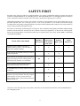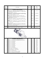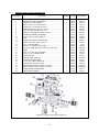
1
OPERATION, PREVENTIVE MAINTENANCE
AND PARTS SUPPORT MANUAL
FOR
MAXIFORCE® G2 AIR LIFTING
BAG SYSTEM
31 MARCH 2014
PN 22-890800G2
Paratech Incorporated
Paratech Europe, Branch of Paratech Inc.
P.O. Box 1000, Frankfort, IL 60423 USA
P.O. Box 174, 5260 Odense S, Denmark
Customer Service: 800.435.9358
www.paratech.com Email: [email protected]
Phone: 815.469.3911 Fax: 815.469.7748
www.paratech.com E-mail: [email protected]
LIST OF EFFECTIVE PAGES
Date of original pages is:
Original……….0……….31 March 2014
Total number of pages in this publication is 54 consisting of the following:
Page
No.
*Change
No.
Title and A…………………… 0
Change Record………………. 0
Change Record-2 blank……… 0
Validation Certificate………... 0
Foreward-1…………………... 0
Forward-2 blank……………... 0
i. through v…………………... 0
* Zero in this column indicates an original page.
Page
No.
*Change
No.
1-1 through 1-9…………….…0
1-10 blank……....…………….0
2-1 through 2-15..…………….0
2-16 blank……..……………...0
3-1 through 3-3……………….0
3-4 blank……………………...0
4-1 through 4-13……………...0
VALIDATION CERTIFICATE
TECHNICAL MANUAL TITLE
OPERATION, PREVENTIVE MAINTENANCE AND PARTS SUPPORT MANUAL FOR
MAXIFORCE® G2 AIR LIFTING BAG SYSTEMS.
TECHNICAL MANUAL NUMBER
DATE
P/N 22-890800G2
CONTRACT/NO.
31 MARCH 2014
I – VALIDATION
Except as stated in II, the technical manual identified above has been satisfactorily validated in
accordance with all requirements of the applicable contract. The technical manual is hereby certified to
be accurate and complete, and the information, instruction, text, and illustration conform in all respects
to the applicable general and detailed specifications.
II – EXCEPTIONS
EXCEPTIONS
NONE
AUTHORIZED BY
Kenneth Nielsen, Chief Operating Officer
Paratech Incorporated
1025 Lambrecht Drive
Frankfort, IL 60423
SIGNATURE OF PUBLICATIONS QUALITY ASSURANCE OFFICER
SIGNATURE ON FILE
QAP20/002/B
DATE
Change Record
Change
No.
QAP20/003/B
Date
Title or Brief Description
Signature of
Validating Officer
FOREWORD
This technical manual conforms to Military Specifications MIL-M-38784 General Style and Format Requirements, MILM-7298 Commercial Equipment Technical Manual and MIL-M-15071 Equipment and Systems Content Requirements
for Technical Manuals. The manual contains description, operating instructions, theory of operation, scheduled
maintenance recommendations and parts lists for MAXIFORCE® G2 Air Lifting Bag Systems manufactured by Paratech
Incorporated, 1025 Lambrecht Road, Frankfort, Illinois 60423-7000.
All pertinent data relative to the MAXIFORCE® G2 Air Lifting Bag Systems is contained herein without specific
reference to other publications. Refer to the table of contents for the arrangement of the contents within this publication.
This manual consists of one volume arranged in four chapters as follows:
Chapter 1 - General Information and Safety Precautions
Chapter 2 - Operation
Chapter 3 - Scheduled Maintenance
Chapter 4 - Parts List
Foreward - 1/(Foreward – 2 blank)
i
TABLE OF CONTENTS
Chapter/Para
LIST OF FIGURES
Title
Page
Figure
1 GENERAL INFORMATION AND SAFETY... 1-1
FIRST PROCEDURES
1-1 Safety Precautions……………………...... 1-1
1-2 Scope Of Manual………………………… 1-1
1-3 Arrangement……………………………... 1-1
1-4 Equipment Function……………………... 1-1
1-5 Interrelationship of Components…….…... 1-1
1-6 Equipment Description………………....... 1-3
1-7 Reference Data……………………….….. 1-7
1-8 Equipment, Accessories and……….......... 1-7
Documents
2. OPERATION……………..……........................ 2-1
2-1 Introduction…………………………...… 2-1
2-2 System Functional Operation………….... 2-1
2-3 Component Interconnection Prior……..... 2-1
to Inflation
2-4 Normal Operating Procedure During…..... 2-3
Inflation
2-5 Changing Air Cylinders…………………. 2-4
2-6 Normal Operating Procedure During……. 2-4
Deflation
2-7 Component Disconnection After………… 2-4
Deflation
2-8 Applications………………………………2-5
2-9 Lift Bag Chemical Compatibility……..... 2-8
1-1
1-2
1-3
1-4
1-5
1-6
1-7
1-8
1-9
MAXIFORCE® G2 Air Lifting Bag System….. 1-2
MAXIFORCE® G2 Lift Bag………………….. 1-3
G2 Pressure Regulator…………………………. 1-4
Single 150 psi ALB Controller G2…………….. 1-5
Dual “Deadman” 150 psi ALB Controller G2.. 1-5
Manual Compressor…………………...………. 1-6
Air Cylinder……………………………………. 1-6
Hoses…………………………………………... 1-6
G2 Inline Relief Valve……………………..
1-6
2-1
2-2
2-3
2-4
2-5
2-6
Quick Connect Coupling Safety Locking Ring 2-2
Typical Applications …………………………... 2-6
Correct Method of Safety Cribbing/Bracing…... 2-7
Lift Bag Stacking and Tandem Combinations.. 2-7
Correct Method for Inflating Stacked Lift Bags..2-8
Using Two Lift Bags to Lift Cylindrical………. 2-8
Objects
4-1 Single 150 psi ALB Controller G2…………….. 4-10
4-2 Dual “Deadman” 150 psi ALB Controller G2… 4-11
4-3 G2 Pressure Regulator………………………….4-13
4. PARTS LIST……………………….………….. 4-1
4-1 Introduction………………………….…... 4-1
4-2 List of Major Components…………….… 4-1
4-3 Parts List Tables……………………….… 4-1
4-4 List of Manufacturers………………….… 4-1
4-5 Exploded Assemblies………………….… 4-10
Controllers and Regulators
LIST OF TABLES
Title
Page
3-1 Air Hose Nipple Replacement…………………. 3-2
3-2 Air Hose Quick Connect Coupling……………..3-2
Replacement
3. MAINTENANCE AND STORAGE……….…. 3-1
3-1 General…………………………………... 3-1
3-2 Preventative Maintenance Plan……...…... 3-1
3-3 Post Operational Preventative…………… 3-1
Maintenance
3-4 Storage…………………………..……….. 3-3
Table
Title
Page
1-1 MAXIFORCE® G2 Air Lifting Bag Reference
Data………………… ..………………………….1-7
4-1 List of Major Components…………………..… 4-1
4-2 MAXIFORCE® G2 Air Lifting Bag System
Components Parts List……...……………………. 4-2
i
SAFETY FIRST
Personnel safety and the prevention of equipment damage were primary considerations during the design and expected
utilization of MAXIFORCE® G2 Air Lifting Bag Systems. When MAXIFORCE® G2 Air Lifting Bag Systems are properly
used in combination with good common sense, an extremely safe method of applying force is realized.
Although the following safety first list is quite extensive, the majority of the precautions are just good common sense for any
personnel qualified in the use of lift bags. However, some of the precautions are not obvious and Paratech strongly
recommends that all operating/assisting/maintenance personnel read and understand the complete safety first procedures in
order to ensure personnel and equipment safety.
Since there are four distinct operational phases of lift bag use: Prior to Inflation, During Inflation and While Inflated, During
Deflation, and After Removal, the safety first list is charted to reflect these applications. As shown in the following table,
during each operational phase, each safety procedure may be required Always (A), If Time Permits (ITP), or Depending
Upon Application (DUA).
SAFETY FIRST PROCEDURE
Regardless of the condition of lift bag use,
SAFETY FIRST is primary to prevent injury or
death and/or equipment damage.
PRIOR TO
INFLATION
DURING
INFLATION
AND WHILE
INFLATED
DURING
DEFLATION
AFTER
REMOVAL
A
A
A
A
A
A
A
A
All personnel at the immediate lift bag site must be
trained and qualified.
All personnel at the immediate lift bag site must be
properly suited up (protective clothing, helmet, eye
protection, gloves, footwear, etc.) at all times
ITP
Never exceed the maximum inflation pressure
marked on the lift bag. (150 psi/10.3 bar)
A
Do not handle hoses or lift bags while the system is
pressurized.
A
A
Do not connect or disconnect system components
when the system is pressurized. The only exception
is disconnection of a safety in-line relief valve
from a controller. Refer to the technical manual for
multiple lift bag use.
A
A
Observance of the following safety first procedures will assure the safe and efficient utilization of the MAXIFORCE® G2
Air Lifting Bag System
ii
PRIOR TO
INFLATION
DURING
INFLATION
AND WHILE
INFLATED
DURING
DEFLATION
Always be on the opposite side of any expected
movement.
A
DUA
A
Always stand clear of a load that is only supported
by lift bag(s). Never be below a lift bag supported
load that has no blocking or cribbing for positive
support. Always “Lift and inch, crib an inch”
A
A
A
Use blocking, shoring and cribbing where ever
possible to support and sustain loads.
A
A
A
Use locking rings on couplings to prevent release
of air pressure due to accidental disengagement of
system components.
A
A
A
DUA
A
A
Be extremely careful to stabilize, as much as
possible, unstable (off-center) loads.
A
A
A
Be careful that hoses are not kinked.
A
A
A
SAFETY FIRST PROCEDURE
Always center load on lift bag or it may be
violently ejected from under load during
pressurization.
Check visually that equipment is not damaged
(scuffs, kinks, tears, ply separation, etc.) and
audibly for the leakage of air.
ITP
AFTER
REMOVAL
A
A
Never stack more than two lift bags on each other
during operation.
A
If required to stack two lift bags for increased
height, always place smaller bag centered on the
top.
A
Use proper sized lift bag(s) for the load conditions
encountered.
A
During transport of lift bags, carry in such a way
so as to protect the inflation nipple even though the
nipple is recessed. Use two men on large lift bags
over 30 pounds (14kg).
A
A
Protect bag with thermal blanket, plywood, etc.
whenever a lift bag will contact a surface in excess
of 150°F (65°C).
ITP
A
(storage)
Never use a lift bag where contact temperatures are
in excess of 220°F (105°C).
A
A
(storage)
iii
SAFETY FIRST PROCEDURE
PRIOR TO
INFLATION
DURING
INFLATION
AND WHILE
INFLATED
DURING
DEFLATION
Never work in the dark. Use flash lights or flood
lights to provide shadow-free illumination of work
area.
ITP
ITP
ITP
Inflate only enough to achieve desired lift.
A
If force must be applied to a small diameter or
small area object, always use plywood, rubber mud
flaps, etc. between the lift bag and the object to
distribute the load more evenly over the lift bag
surface. Otherwise safe maximum lifting force
cannot be applied.
A
Always evaluate the condition prior to execution in
order to determine which size lift bag to use and
where to apply it to achieve the desired result.
AFTER
REMOVAL
ITP
Always inflate a lift bag slowly to prevent possible
shifting of load. Stop if load begins to shift,
stabilize and block load before continuing.
A
Be sure all valves between air source and lift
bag(s) are in a closed position before turning on air
source to system. This will prevent an uncontrolled
lift. Also open air supply source slowly to prevent
damage to regulator.
A
Never lift with a lift bag directly in contact with
sharp or pointed objects that may puncture, abrade
or otherwise damage the lift bag.
DUA
Always have 3 points of contact to ensure a stable
foundation when lifting unsecured loads.
DUA
Undue haste could result in injury to personnel and
damage/render the lift bag system useless.
A
Keep as far away as possible from lift bag(s). Hose
length governs this safety first procedure.
Never inflate a lift bag over 30 psi (2 bar) when
not under load.
A
A
A
A
A
A
(maintenance)
iv
CHAPTER 1
GENERAL INFORMATION
1-1 SAFETY PRECAUTIONS
1-4.3 In addition to use during emergency situations,
MAXIFORCE® G2 Air Lifting Bag Systems are also
used effectively used for:
Refer to the Safety First procedures Chapter 1, General
Information and Safety Precautions for the procedures to
be observed to assure safe and efficient utilization of
MAXIFORCE® G2 Air Lifting Bag Systems.
a. Preventive
and/or
corrective
maintenance
procedures where positioning and aligning heavy
equipment and machinery in mills, manufacturing
facilities and maintenance shops is required such as
removing wheels, pulleys and gears from large machinery.
1-2 SCOPE OF MANUAL
This technical manual provides instructions for the
operation, preventive maintenance and parts support for
MAXIFORCE® G2 Air Lifting Bag Systems
manufactured by Paratech Incorporated, 1025 Lambrecht
Rd, Frankfort, Illinois 60423-7000.
b. Lifting or shifting pipelines requiring welding and
maintenance.
c. Breaking out granite and marble blocks and slabs in
quarrying operations.
1-3 ARRANGEMENT
Refer to the Table of Contents for arrangement of the
subject matter in this manual.
d. Re-railing railroad and mining cars, pre-stressing
support columns, general maintenance requiring lifting in
rail, mining, underground and subway work.
1-4 EQUIPMENT FUNCTION
1-4.1 MAXIFORCE® G2 Air Lifting Bag Systems are
multi-application, portable inflation systems used for lift
and displacement of heavy objects, up to 178,400 lbs
(80,920 kilograms), while requiring less than 1 inch (25
centimeters) of bag insertion clearance. Total capable lift
(utilizing two stacked bags) is 40 inches (100
centimeters). Inflation may be obtained from any air
source (self-contained compressed air cylinder, air
compressor, truck air brake system, building compressed
air system, foot pump, etc.) capable of supplying 150 psi
(10.3 bar) pressure.
e. Lifting operations underwater or on unstable, soft
ground (mud, sand, snow, strewn debris, etc.) where
conventional jacking equipment tends to sink.
f. Since the lift bags contain no spark producing parts,
they may also be used safely in explosive environments.
1-5 INTERRELATIONSHIP OF COMPONENTS.
Refer to figure 1-1 for the interrelationship of the six basic
components (air source, G2 pressure regulator, G2
controller, safety inline relief valve, interconnecting hose,
and G2 lift bag) comprising MAXIFORCE® G2 Air
Lifting Bag Systems and their relative sizes.
1-4.2 MAXIFORCE® G2 Air Lifting Bag Systems are
designed for use in emergency situations such as building
collapse, structural containment, vehicular extrications,
industrial entrapment, and excavation collapse and
containment.
1-1
Figure 1-1. MAXIFORCE® G2 Air Lifting Bag System
Chapter 2 “OPERATION” for component connection
and system operation.
For further component explanation, see the chapter
shown under the component within figure 1-1. See
1-2
1-6
EQUIPMENT DESCRIPTION
1-6.1 G2 LIFT BAG
Figure 1-2. MAXIFORCE® G2 Lift Bag
MAXIFORCE® G2 Lift Bags (figure 1-2) are composite
items fabricated from neoprene, reinforced with six layers
(three per side) of Kevlar reinforced fabric for strength
and rigidity even at full inflation pressure of 150 psi (10.3
bar).
used to assist in transport and insertion positioning prior
to inflation.
Corners and edges has the maximum tonnage molded into
the bag and filled with bright yellow silicone adhesive to
help identify and quickly select an air bag in low light
situations. The edge tonnage has a center mark to identify
the center of the bag in low insertion applications where
the center of the bag cannot be seen.
All Lift Bags incorporate molded raised interlocking
surfaces designed for maximum friction and holding
capability.
A yellow, symbol driven, warning label is permanently
molded into the bag surface for quick reference and
reminders of safety related warnings and information.
All air bags, except the KPI-1, have a bright yellow "X"
molded into each side to provide high visibility during
pre-inflation centering.
Each Lift Bag is proof tested at twice the operating (full
inflation) pressure and has a minimum burst pressure of
four times the operating 150 psi (10.3 Bar) pressure. Refer
to Table 1-1 for a summary of the technical data for each
MAXIFORCE® G2 Lift Bag.
The left hand threaded air inlet fitting is recessed to help
protect the fitting from damage. A tethered nipple cap is
provided to protect from contamination and also to help
protect the outside surface of the fitting. The tether is to
prevent accidental loss of the cap.
Tethering eyelets are molded into larger air bags to be
1-3
1-6.2 G2 PRESSURE REGULATOR.
Figure 1-3 G2 Pressure Regulator
The G2 pressure regulator (figure 1-3) reduces inlet
pressure of up to 5,500 psi (379 bar) to 0 psi (0 bar). The
pressure regulator is designed to mate with a CGA346/347 adapter fitting. Other fittings are available such
as CGA-580 (nitrogen cylinder adapter), DIN nipple and
nut assembly and British nipple and knob assemblies are
also available.
occurs at high expansion ratios during regulator operation.
A 10 micron internal filter is incorporated in the pressure
regulator. Coarser filters are available if excessive
contamination is a problem.
The shut-off valve is either opened to permit regulated
delivery air to pressurize the lift bag system or closed to
prevent (seal off) regulated delivery air. The pressure
adjustment knob is turned to control the delivery pressure
up to 200 psi (13.8 bar) maximum.
The G2 pressure regulator incorporates a piston sensor
and soft seated main valve to provide bubble tight service.
The adjusting knob is sensitive to settings yet low
operating torque.
A 200 psi (13.8 bar) safety relief valve is installed to
prevent delivery pressures exceeding 200 psi (13.8 bar).
The G2 pressure regulator will operate with any breathing
air. When using any gaseous media, it is necessary to
remove moisture to prevent "icing"; a condition that
Supply and delivery pressure gauges are installed to
monitor their respective pressures.
1-4
1-6.3
G2 CONTROLLERS.
Figure 1-4. Single 150 psi ALB Controller G2
Figure 1-5. Dual “Deadman” 150 psi ALB Controller G2
Two controllers are available for use with
MAXIFORCE® G2 Air Lifting Bag Systems. First, the
single 150 psi ALB controller G2 (figure 1-4) which is
single input/single output. Second, the dual “deadman”
150 psi ALB controller G2 (figure 1-5) which is single
input/dual output. Each are easily identified for use with
150 psi by bright yellow gauge shroud and rocker lever.
The delivery gauges are provided to monitor the air
pressure applied to the lift bag(s). They are protected by
an aluminum gauge shroud to help protect gauges from
accidental damage.
155 psi (10.7 bar) non-adjustable safety relief valves are
installed into the controller to limit the applied air pressure
and prevent over pressurizing. Due to the tolerance
associated with the mechanical vent relief valves;
controllers are set 5 psi (0.4 bar) higher to 155 psi (10.7
bar) to insure the system always gets to 150 psi (10.3 bar)
operation.
Both controllers incorporate locking, quick connect,
couplings to prevent accidental disconnection during use.
Bright yellow rocker lever controls permit regulated air
pressure to inflate the lift bag or deflate to relieve system
air pressure to collapse the lift bag. The rocker lever
inflates “UP” and deflates “DOWN” by activating control
valve assemblies beneath their respective side of the lever.
The lever insures that the up and down controls cannot be
operated at the same time.
The dual “deadman” controller has a second set of
controls that are identical yet independent from the first
set so two air bags can be controlled at the same time yet
independently. If using the dual “deadman” controller in
a single lift bag operation, either set can be used.
1-5
Figure 1-8. Hoses
Figure 1-6. Manual Compressor
1-6.6 HOSES. Hoses (figure 1-8) are used to convey air
from the air supply source to the lift bag(s). All hoses are
equipped with locking, quick connect, fittings to prevent
their accidental disconnection.
1-6.4 MANUAL COMPRESSOR. The manual
compressor (figure 1-6) is a foot/hand lever operated
compressor used to deliver pressurized air to the air bag.
A sliding valve collar permits isolating one of the two
cylinders thereby increasing the delivered pressure and
decreasing the delivered volume by a factor of 2.
All hoses are general purpose Ø3/8” inside diameter PVC
(vinyl) core, single spiral poly yarn braid reinforced and a
PVC abrasion resistant cover.
The service temperature range is -15°F to +150°F (-25°C
to +65°C). All hoses have a working pressure of 300 psi
(20.7 Bar) with a 4:1 safety factor.
Available hose lengths are 16 foot (5meter), 32 foot (10
meter) and 50 foot (15 meter). Available color in all
lengths are red, yellow, blue, green, grey, and black.
Figure 1-7. Air Cylinder
1-6.5 AIR CYLINDER. The air cylinder (figure 1-7) is
used to store compressed air for use on the air bag. The
shut off valve that permits or prevents the flow of
compressed air to the G2 regulator.
The pressure gauge measures the amount of pressure
within the tank.
Figure1-9. G2 Inline Relief Valve
1-6
1-6.7 G2 INLINE RELIEF VALVE. The G2 safety
inline relief valve (figure 1-9) is designed to keep
MAXIFORCE® G2 lift bags fully and properly inflated
when the lift bag(s) are; 1. Disconnected from the
controller and 2. When excess pressure must be
automatically relieved due to shifting loads and/or
temperature changes.
regulators, self-contained compressed air cylinders, etc.
1-7 REFERENCE DATA. Reference data pertaining
to MAXIFORCE® G2 lift bags system components are
summarized for quick reference in Tables 1-1 and 1-2.
1-8 EQUIPMENT, ACCESSORIES,
DOCUMENTS.
The safety inline relief valve consists of an air inlet and
outlet with locking ring quick connect fitting. A shut-off
valve is used to isolate the lift bag and a non-adjustable
safety relief valve designed to relieve lift bag pressures in
access of 165psi. Inline relief valves for 150 psi are easily
identified by a bright yellow shut off knob.
1-8.1 EQUIPMENT SUPPLIED. Data pertaining to the
dimensions and weight of MAXIFORCE® G2 lift bags
are presented in Table 1-2.
1-8.2 ACCESSORIES. Accessories used in conjunction
with MAXIFORCE® G2 lift bag systems are listed with
sufficient descriptive information regarding their use and
application in Chapter 4, Parts List.
1-6.8 FITTINGS. A variety of adapters, couplings and
air fittings are available to permit alternate air sources to
inflate the MAXIFORCE® G2 lift bag(s) or enable
various air powered tools and accessories to be equipped
with the same fittings permitting convenience of operation
and/or combining equipment resources such as hoses,
1-8.3 DOCUMENTS. No documents other than this
publication are required as supporting literature for
MAXIFORCE® G2 lift bag system.
Table 1-1. MAXIFORCE G2 Lift Bag Reference Data
LIFT BAG CONSTANTS:
Base Material………………………………………………………………………………………... Neoprene
Reinforcing Material …………………………………………………………………………...…… Kevlar
Number of Reinforcing Layers (Each Side)………………………………………………………… 3
Surface Type………………………………………………………………………………………… Molded Non-Slip
Short Term Temperature Range °F (°C)…………………………………………………………….. -75 (-60) to +200 (+105)
Continuous Duty Temperature Range °F (°C)………………………………………………………. -40 (-40) to +150 (+65)
Maximum Working Pressure PSI (Bar)……………………………………………………………... 150 (10.3)
Test Pressure PSI (Bar)……………………………………………………………………………… 300 (20.6)
1-7
22
12
20
18
11
16
10
14
HEIGHT (IN)
12
9
8
10
8
6
HEIGHT (IN)
7
4
2
6
0
0
5
5
10 15 20 25 30 35 40 45 50 55 60 65 70 75 80 85 90
U.S. TONS
4
3
2
1
0
0
2
4
6
8
10
12
14
16
18
20
22
24
U.S. TONS
Table 1-1. MAXIFORCE® G2 Lift Bag Reference Data (Continued)
1-8
26
28
30
32
34
MAXIFORCE AIR BAGS TECHNICAL DATA
PN
MODEL
DIMENSIONS W/O EYELETS &
NIPPLE
STORAGE DIMENSIONS
(W/EYELETS)
WEIGHT
MAX LIFT
CAPACITY
MAX
WORK
PRESSURE
MAX LIFT
HEIGHT
MAX AIR
CAPACITY
mm
INCH
mm
INCH
KG
LBS
METRIC
TON
US TONS
BAR
PSI
mm
INCH
LITERS
CU.
FT
22-888110G2
KPI-1
152 X 152 X 19
6 X 6 X 0.75
178 X 178 X 19
7.0 X 7.0 X 0.75
0.6
1.2
1.3
1.5
10.3
150
76
3.0
2.94
0.10
22-888120G2
KPI-3
152 X 305 X 19
6 X 12 X 0.75
178 X 331 X 19
7.0 X 13.0 X 0.75
1.0
2.3
3.2
3.5
10.3
150
89
3.5
8.10
0.29
22-888130G2
KPI-5
254 X 254 X 19
10 X 10 X 0.75
280 X 280 X 19
11.0 X 11.0 X 0.75
1.4
3.1
4.9
5.4
10.3
150
137
5.4
18.36
0.65
22-888135G2
KPI-8
305 X 305 X 22
12 X 12 X 0.88
331 X 331 X 19
13.0 X 13.0 X 0.75
2.5
5.5
7.5
8.2
10.3
150
163
6.4
37.34
1.32
22-888138G2
KPI-10
305 X 457 X 22
12 X 18 X 0.88
338 X 338 X 22
13.1 X 19.0 X 0.88
3.7
8.3
11.7
12.9
10.3
150
180
7.1
66.26
2.34
22-888140G2
KPI-12
381 X 381 X 22
15 X 15 X 0.88
381 X 564 X 22
16.3 X 16.3 X .88
4.0
8.8
12.4
13.7
10.3
150
206
8.1
74.77
2.64
22-888150G2
KPI-17
381 X 533 X 22
15 X 21 X 0.88
381 X 564 X 22
15.0 X 22.2 X 0.88
5.4
12.0
17.3
19.0
10.3
150
226
8.9
125.61
4.44
22-888160G2
KPI-22
508 X 508 X 22
20 X 20 X 0.88
508 X 539 X 22
20.0 X 21.2 X 0.88
7.2
15.9
23.2
25.6
10.3
150
274
10.8
188.39
6.65
22-888165G2
KPI-28
508 X 660 X 22
20 X 26 X 0.88
508 X 691 X 22
20.0 X 27.2 X 0.88
9.1
20.1
30.9
34.0
10.3
150
299
11.8
278.86
9.85
22-888170G2
KPI-32
610 X 610 X 22
24 X 24 X 0.88
610 X 640 X 22
24.0 X 25.2 X 0.88
10.0
22.0
34.4
38.0
10.3
150
330
13.0
318.00
11.23
22-888180G2
KPI-35L
381 X 1066 X 22
15 X 42 X 0.88
412 X 1096 X 22
16.2 X 43.2 X 0.88
11.1
24.5
35.8
39.5
10.3
150
241
9.5
254.12
8.97
22-888190G2
KPI-44
711 X 711 X 22
28 X 28 X 0.88
712 X 745 X 22
28.0 X 29.3 X 0.88
13.6
30.0
47.8
52.7
10.3
150
388
15.3
560.50
19.80
22-888195G2
KPI-55
812 X 812 X 25
32 X 32 X 1
813 X 872 X 25
32.0 X 34.3 X 1
20.5
45.2
63.3
69.7
10.3
150
432
17.0
864.50
30.50
22-888200G2
KPI-74
939 X 939 X 25
37 X 37 X 1
940 X 999 X 25
37.0 X 39.3 X 1
26.3
58.0
80.9
89.2
10.3
150
508
20.0
1227.00
43.30
Table 1-1. MAXIFORCE® G2 Lift Bag Reference Data
1-9(1-10 blank)
CHAPTER 2
OPERATION
2-1
INTRODUCTION
d. As air flows into the lift bag, it increases in height
resulting in a corresponding lift/displacement. Maximum
lift/displacement force occurs at approximately one inch
of inflation height (minimum reduction of the lift bag
cross section). As additional air flows into the lift bag,
the cross section reduces as the height increases resulting
in a corresponding reduction in lift/displacement
capacity.
2-1.1 MAXIFORCE® G2 Lifting Bag Systems are
multi-application, portable inflation systems used for lift
and displacement of heavy rigid objects, up to 178,400
pounds (80,920 kilograms), while requiring less than 1
inch (2.5 centimeters) of bag insertion clearance. Total
capable lift (utilizing two stacked lift bags) is 40 inches
(100 centimeters). Inflation may be obtained from any air
source (self-contained compressed air cylinder, air
compressor, truck air brake system, building compressed
air system, foot pump, etc.) capable of supplying 150 psi
(10.3 Bar) pressure.
e. When the lift bag(s) are to be partially or fully
deflated, control(s) on the controller are operated to
perform this function as well as prevent any further inlet
pressure from flowing beyond the controller.
2-1.2 MAXIFORCE® G2 Lifting Bag Systems are
designed for use in emergency situations such as building
collapse, structural containment, vehicular extrication,
industrial entrapment, and excavation collapse and
containment. The specific situation requiring the use of a
MAXIFORCE® G2 Lifting Bag System will generally
determine the size and quantity of lift bag(s) to be utilized
in combination with each other.
f. At the conclusion of operation, the air supply is
“turned-off”, any residual system air pressure is relieved
(“bled off”) through the controller, the system
components are disconnected, inspected and stored for
later use.
2-3 COMPONENT INTERCONNECT PRIOR
TO INFLATION.
See Chapter 2-8 (page 2-5) for application examples.
WARNING
2-2 SYSTEM FUNCTIONAL OPERATION.
Functionally, an interconnected MAXIFORCE® G2
Life Bag System operates as follows:
Refer to the SAFETY FIRST instructions
preceding chapter 1 for those safety first
procedures to be followed for each specific
operational phase of the application at hand.
Regardless of the lift bag applications or
environmental conditions, strict adherence to
SAFETY FIRST is essential to prevent
personnel injury/death and/or equipment
damage. It may make a difference between
saving a life or endangering/sacrificing
another life.
a. A self-contained air cylinder, air compressor, foot
pump or alternate air supply provides the necessary
volume and pressure to pressurize the system and
ultimately inflate the lift bag.
b. After a lift bag(s) is properly positioned for a
lift/displacement, the air supply is “turned on”. High
pressure air is reduced by the pressure regulator to a
usable 165 psi (11.3 Bar)
2-3.1 The following procedures describe in detail a
typical interconnection of the previously described
components comprising a MAXIFORCE® G2 Air
Lifting Bag System. This procedure can be accomplished
by trained personnel in less than one minute. If the
specific application does not require the use of all of the
referenced components or some of the components are
not available, elimination of the non-applicable steps and
proceed with the interconnection. Any adapters,
c. The reduced air pressure is supplied via an air hose
to a 150 psi ALB controller G2. The controller permits
air to flow via air hose(s) to either one or two lift bags
permitting a controlled lift/displacement. In the line
between the controller and the lift bag(s) are inline relief
valve(s) to maintain proper pressure in the lift bags while
disconnected from the controller.
2-1
couplings and/or fittings required in conjunction with the
components are addressed generally but not specific
during the interconnection. It is assumed these parts are
available and will be installed where required in the
system.
a. Remove all dust, dirt, oil or grease from the
MAXIFORCE® G2 Air Lifting Bag System
components. Do not use any system components without
first cleaning off any contaminants.
b. Inspect all inlet and delivery fittings for any
damage that will permit air leakage. Do not use any
component if an air leakage condition is suspected or
exists.
2-3.2 Refer to Table 1-1 to determine the required lift
bag(s) for the load/displacement and full inflation height
demands for the application at hand. Once proper
lift/displacement and height configuration is determined
and the individual components selector, it is only
necessary to clean, where required, the individual
components sufficiently to clear them of any
contaminates that would prevent their full engagement
and proper locking to each other and to interconnect the
components.
c. Attach the high pressure inlet of the G2 pressure
regulator to the air supply. Tighten connection to prevent
air leakage. Do not over tighten.
d. Check that the G2 pressure regulator shut-off valve
is closed (full clockwise). Check that the G2 pressure
regulator
pressure
adjusting
knob
is
full
counterclockwise to close the internal needle valve (no
flow through the G2 pressure regulator).
WARNING
Refer to the SAFETY FIRST instructions
preceding chapter 1 and adhere to applicable
“prior to inflation” procedures.
e. Attach an air hose quick connect coupling to the G2
pressure regulator air delivery nipple using the
appropriate interconnecting fittings as required.
WARNING
f. Attach the inlet quick connect coupling on a 150
psi ALB controller G2 to the air hose quick connect
nipple.
Most steps within this chapter discuss
component connection. Check that the quick
connect coupling is fully engaged and locked
into position to assure a leak free connection.
Be certain to turn the safety locking ring on any
quick connect coupling to the locked position
as shown in figure 2-1.
g. Attach the inlet quick connect nipple on a G2 safety
inline relief valve to the delivery quick connect coupling
on a 150 psi ALB controller G2. Check that the G2 safety
inline relief valve shut-off valve is closed (full
clockwise).
h.
If using a dual "deadman" 150 psi ALB
controller G2, attach the inlet quick connect nipple on a
second G2 safety inline relief valve to the second
delivery quick connect coupling on the dual “deadman”
150 psi ALB controller G2. Check that the G2 safety
inline relief valve shut-off valve is closed (full
clockwise).
i. Attach an air hose quick connect nipple to the G2
safety inline relief valve delivery quick connect coupling
using the appropriate interconnecting fittings as required.
Connect additional lengths of air hose of the same color
as required.
Figure 2-1 Quick Connect Coupling Safety
Locking Ring
2-2
j. If a second G2 safety inline relief valve is used,
attach air hose quick connect nipple to the second G2
safety inline relief valve delivery coupling using the
appropriate interconnecting fittings as required. A
different colored air hose should be used to permit the
rapid and positive identification of the lift bag connected
to each side of the controller. Connect additional lengths
of air hose of the same color as required.
WARNING
Do not adjust the G2 pressure regulator to
exceed the maximum pressure rating of any
component in the system apparatus or 165 psi
(11.3.bar) whichever is less.
b. Adjust the G2 pressure regulator pressure
adjusting knob (turn clockwise) to increase the delivery
pressure from 0 psi to 165 psi (11.3 bar).
k. Attach a lift bag nipple to the air hose quick
connect coupling.
c. Slowly open (turn counter-clockwise) the G2
pressure regulator shut-off valve. The delivery pressure
should remain at 165 psi (11.3 bar).
l. If a second lift bag is being used, attach the second
lift bag nipple to the other air hose quick connect
coupling.
d. Open the shut-off valve on the G2 safety inline relief
valve(s).
m. The MAXIFORCE® G2 Air Lifting Bag System
is now fully interconnected and can be positioned with
any required shoring and/or cribbing, and inflated for a
lift/displacement.
2-4
NORMAL OPERATING
DURING INFLATION.
NOTE:
When operating the lift bag, always inflate slowly
and only lift or move the amount necessary.
PROCEDURE
e. Press the inflate side of the rocker lever of the 150
psi ALB controller G2 or dual “deadman” 150 psi ALB
controller G2 repeatedly to slowly inflate the lift bag to
the required height or 150 psi (10.3 bar). Inflating the lift
bag(s) slowly will minimize the possibility of shifting. If
a second lift bag is interconnected to the controller,
operate the second rocker lever to slowly inflate the
second lift bag. The lift bags may be inflated
simultaneously or alternately as desired by the operator.
Proceed as follows to inflate the lift bag(s) after the
individual components are interconnected, (per chapter
2-3) the lift bag(s) are positioned and the necessary
shoring and/or cribbing is in position.
WARNING
f. With the lift bag inflated to the desired height/
pressure close (turn clockwise) the shut-off valve on the
G2 safety inline relief valve(s).
Refer to the SAFETY FIRST instructions
preceding chapter 1 and adhere to the applicable
"during and while inflated" procedures.
g. If additional lift bags are required for the
application, proceed as follows:
WARNING
1. Determine the lift bag to remain inflated and in
position. Be sure the shut-off valve on the associated G2
safety inline relief valve.
Be sure all shut-off valves are in a closed
position prior to opening the air supply to the
system; this will prevent an uncontrolled
lift/displacement.
2. Before disconnecting the G2 safety inline relief
valve from the G2 controller, be sure to release the
pressure between the components by pressing the
“deflate” side of the rocker lever. Be sure the gauge on
the controller reads 0 psi before disconnection. Release
the safety locking ring on the quick connect coupling
between the G2 controller and the G2 safety inline relief
valve. Disengage the coupling lock ring to release the G2
safety inline relief valve from the G2 controller.
a. Slowly open (turn counter-clockwise) the air
supply to the G2 pressure regulator. The supply pressure
will be indicated on the air supply pressure gauge as well
as on the G2 pressure regulator supply pressure gauge.
The delivery pressure gauge on the G2 pressure regulator
should indicate 0 psi.
2-4
3. Attach the inlet port quick connect nipple on a
G2 safety inline relief valve to the outlet port quick
connect coupling on the G2 controller. Check that the G2
safety inline relief valve shut-off valve is closed (full
clockwise).
e. Slowly open (turn counter clockwise) the air
supply to the G2 pressure regulator. The supply pressure
will be indicated on the air supply pressure gauge as well
as on the G2 pressure regulator supply pressure gauge.
The delivery pressure gauge on the G2 pressure regulator
should indicate 0 psi.
4. Attach an air hose quick connect nipple to the G2
safety inline relief valve delivery coupling using the
appropriate interconnecting fittings as required. Connect
additional lengths of air hose as required.
f. Adjust the G2 pressure regulator pressure
adjusting knob (turn clockwise) to increase the delivery
pressure from 0 psi to 165 psi (11.3 Bar)
5. Attach a G2 lift bag nipple to the air hose quick
connect coupling.
g. Slowly open (turn counter clockwise) the G2
pressure regulator shut-off valve. The delivery pressure
should remain at 165 psi (11.3 Bar).
6. Press the inflate side of the rocker lever of the
150 psi ALB controller G2 or dual “deadman” 150 psi
ALB controller G2 repeatedly to slowly inflate the lift
bag to the required height or 150 psi (10.3 bar). Inflating
the lift bag(s) slowly will minimize the possibility of
shifting.
2-6 NORMAL OPERATING
DURING DEFLATION.
NOTE
If a lift bag(s) is to be removed after it is
deflated, shoring or cribbing must be in
position, as required, to restrain the load
permitting the removal of the lift bag(s).
7. Adhere to procedural steps 1 through 6 to add
any additional quantity of lift bags required for the
application.
2-5
PROCEDURE
a. To either partially or fully deflate an inflated lift
bag(s) disconnected from a controller, open and close as
required the shut-off valve on the G2 safety inline relief
valve to slowly achieve the desired deflation. The lift bag
design prevents it from deflating rapidly. Alternately
opening and closing the shut-off valve will permit a more
slowly controlled deflation. This prevents any quick load
movements that may cause damage or personnel injury.
Repeat for any additional lift bag(s) disconnected from
the controller that can be partially or fully deflated.
CHANGING AIR CYLINDERS.
NOTE
If the air source for a given application requires
the use of air cylinder, it should be changed
during inflation whenever the air cylinder
pressure falls below 200 psi (13.8 Bar).
a. Close (turn clockwise) the air cylinder and the
G2 pressure regulator shut-off valves. The supply
pressure gauge on the pressure regulator should
indicate 0 psi. The delivery pressure gauge will
indicate the regulated pressure until the internal
pressure is relieved, any residual system air pressure
will be relieved through the controller.
b. To either partially or fully deflate an inflated lift
bag (s) connected to a controller, press and release the
deflate side of the rocker lever repeatedly to slowly
deflate the lift bag. Repeat for an additional lift bag
connected to the controller if it can be partially or fully
deflated.
b. Turn the G2 pressure regulator pressure adjusting
knob full counter clockwise to close the internal needle
valve (no flow through the pressure regulator).
c. Gather the system components together in
preparation for movement to another work area or for
disconnection, post inspection and storage.
c. As required, turn the nut on the G2 pressure
regulator high pressure inlet or interconnecting air
cylinder to pressure regulator fitting to the unlocked
position. Disengage the inlet nipple to release the air
cylinder from the G2 pressure regulator.
2-7 COMPONENT DISCONNECTION AFTER
DEFLATION.
d. Attach the high pressure inlet on the G2 pressure
regulator to a full air cylinder. Tighten all connections
just enough to prevent air leakage. Do not over tighten.
The following procedures describe in detail a typical
disconnection of the previously described components
2-4
comprising a MAXIFORCE® G2 Air Lifting Bag
System. This procedure can be accomplished by trained
personnel in less than one minute. If the specific
application did not require the use of all of the referenced
components or some of the components are not available,
eliminate the non-applicable steps and proceed with the
disconnection. Any adapters, couplings and/or air fittings
used in conjunction with the components are not
addressed during the disconnection.
f.
Turn the safety locking ring on the air hose quick
connect coupling, interconnecting the G2 pressure
regulator to the unlocked position. Disengage the
coupling lock ring to release the air hose from the G2
pressure regulator.
g. As required, turn the safety locking ring on the air
source fitting quick connect coupling, interconnecting
the G2 pressure regulator to the unlocked position.
Disengage the coupling lock ring or other fitting to
release the pressure regulator from the air source.
a.
After the lift bag(s) has been removed from its
lift/ displacement position and the interconnected system
components are gathered together, check that the supply
pressure gauge and delivery pressure gauge on the G2
pressure regulator indicate 0 psi.
h.
If the components are not to be immediately
reused, perform the post operation inspection and storage
in accordance with Chapter 3.
1. If the supply pressure gauge indicates a pressure
other than 0 psi turn off the air supply. Any residual
system air pressure will be relieved through the
controller. If a significant pressure is still indicated, the
air supply shut-off valve is probably defective and air
leakage should be anticipated when the air supply is
disconnected from the G2 pressure regulator.
2-8 APPLICATIONS.
2-8.1 MAXIFORCE® G2 Air Lifting Bag Systems are
multi-application, portable inflation systems used for lift
and displacement of heavy rigid objects, up to 178,400
pounds (80,920 kilograms), while requiring less than 1
inch (2.5 centimeters) of bag insertion clearance. Total
capable lift (utilizing two stacked lift bags) is 40 inches
(100 centimeters).
2. If the delivery pressure gauge on the G2 pressure
regulator indicates a pressure other than 0 psi, be sure the
air supply is turned off and press the deflate side of the
rocker lever to exhaust air from the system.
2-8.2 As shown in figure 2-2, MAXIFORCE® G2 Air
Lifting Bag Systems are designed for use in emergency
situations such as building collapse, structural
containment,
vehicular
extrications,
industrial
entrapment, and excavation collapse and containment.
b.
Turn the safety locking ring on the air hose quick
connect coupling, interconnecting the lift bag, to the
unlocked position. Disengage the coupling lock ring to
release the lift bag from the air hose.
2-8.3 In addition to use during emergency situations,
MAXIFORCE® G2 Air Lifting Bag Systems are also
effectively used for:
c. Turn the safety locking ring on the G2 safety inline
relief valve quick connect coupling, interconnecting the
air hose, to the unlocked position. Disengage the
coupling lock ring to release the air hose from the G2
safety inline relief valve.
a.
Preventive and/or corrective maintenance
procedures where positioning and aligning heavy
equipment and machinery in mills, manufacturing
facilities and maintenance shops is required such as
removing wheels, pulleys and gears from large
machinery.
d. Turn the safety locking ring on the 150 psi ALB
controller G2 quick connect coupling, interconnecting
the G2 safety inline relief valve, to the unlocked position.
Disengage the coupling lock ring to release the G2 safety
inline relief valve from the 150 psi ALB controller G2.
b. Lifting or shifting pipelines requiring welding and
maintenance.
e.
If a dual “deadman” 150 psi ALB controller G2
is used with two G2 safety inline relief valves and
associated lift bags, repeat preceding steps b through d.
c. Breaking out granite and marble blocks and slabs in
quarrying operation
2-5
Figure 2-2
2-6
d.
Re-railing railroad and mining cars, pre-stressing
support columns, general maintenance requiring lifting
in rail, mining, underground and subway work.
drop distance in the event of air loss after inflation. After
full safety cribbing/bracing is in place, the lift bag may
be slowly deflated and removed, and the support
cribbing/bracing removed, allowing the load to rest fully
on the safety cribbing/bracing.
e. Lifting operations underwater or on unstable, soft
ground (mud, sand, snow, strewn debris, etc.) where
conventional jacking equipment tends to sink.
f. Since the lift bags contain no spark producing parts,
they may also be used safely in explosive environments.
2-8.4 In addition to the SAFETY FIRST Procedures in
the front of this publication, the following general
application notes and procedures should be followed
whenever a MAXIFORCE G2 Air Lifting Bag System is
to be employed.
a.
All procedures should be used as guidelines, not
absolute dictates. Any previous application may, as a
result of a seemingly inconsequential change, require
modification or possibly completely new procedures to
achieve the same result.
Figure 2-3. Correct Method of Safety Cribbing/Bracing
f. Lifting capacity does not increase by stacking 2 lift
bags one on top of the other; only the lifting height
increases. Lifting capacity is controlled by the smaller
bag capacity. Use lift bags, side-by-side, to additively
increase capacity by inflating the lift bags
simultaneously. (Figure 2-4)
b.
Lift bags are relatively lightweight. The
maximum weight is 60 pounds (27.2 kg). All lift bags
over 8 pounds incorporate at least two lifting eyelets.
c.
If a lift bag is being used to lift or displace a thin
surface or material, use plywood between the lift bag and
the surface to more evenly distribute the applied force.
d.
If a lift bag will be used on an icy, greasy or
otherwise slick surface, use a granular material such as
sand between the lift bag and the surface to increase the
coefficient of friction, thereby preventing the lift bag
from slipping.
e.
Build support cribbing/bracing height to a point
that just allows the lift bag(s) to be inserted. Safety
cribbing/bracing must be installed as the load is being
lifted, remembering the generally applied rule to “lift an
inch, crib an inch”. Care must be exercised to avoid
injury and damage in the event of a drop and/or load shift
(figure 2-3). The top support cribbing/bracing layer must
be sufficiently solid to prevent a cribbing/bracing shift
and collapse during inflation when the lift bag(s) take on
the characteristic double dome shape. Build safety
cribbing/bracing after the desired lift to minimize the
Figure 2-4. Lift bag Stacking and Tandem
Combinations
g. If the lift requirement demands the use of two
stacked lift bags, (figure 2-5) the smaller lift bag be on
top (A) and the bottom lift bag inflated first until top lift
bag contacts with the load (B). The top lift bag is then
inflated to achieve the desired lift(C). If additional lift is
required at full inflation of the top lift bag is further
inflated (D).
2-7
solutions. Each commodity is assigned an alpha
character to denote its expected effect upon the lift bag.
The specific ratings in this table are based upon
published literature from various polymer suppliers and
manufacturers and “Chemical Resistance Guide for
Elastomers II” published by Compass Publications,
copyright 1994. Paratech is unable to guarantee their
accuracy and therefore assumes no liability for the use
thereof.
A. - EXCELLENT SERVICE
Long service may be expected with little reduction in
properties due to the exposure. Suitable for continuous
service.
Figure 2-5. Correct Method for Inflating
Stacked Lift Bags
B. - GOOD SERVICE
Good service may be expected, but properties will be
affected by the exposure. Usually suitable for continuous
and intermittent service.
h. When lifting large cylindrical objects (Figure 26), use a lift bag on both sides of cylinder and wedges to
provide an even lift.
C. - FAIR SERVICE
Fair service may be expected if exposure is limited or
infrequent. Not recommended for continuous use but
may give some service if it is the only option available.
U. - NOT RECOMMENDED FOR CONTINUOUS
USE
Figure 2-6. Correct Method of Inflating
Stacked Lift Bags
BLANK - INSUFFICIENT INFORMATION
The table positions which are not rated indicate
insufficient information at the time of publication to
determine an accurate rating.
2-9 LIFT BAG CHEMICAL COMPATIBILITY
Use the following chemical compatibility table only as a
guide in determining the MAXIFORCE® G2 Lift Bag
resistance to solvents, acids, salts and other chemical
2-8
A
Acetamide .......................................... B
Acetic Acid 5% .................................. A
Acetic Acid 30% ................................ A
Acetic Acid, Hot High Press .............. C
Acetic Acid, Glacial........................... U
Acetic Anhydride ............................... A
Acetone .............................................. C
Acetophenone .................................... U
Acetyl Acetone .................................. U
Acetyl Chloride .................................. U
Acetylene ........................................... B
Acetylene Tetrabomide ...................... B
Acrylonitrile....................................... C
Adipic Acid........................................ A
Aero Lubriplate.................................. A
Aero Safe 2300 .................................. U
Aero 2300W ...................................... U
Aero Shell IAC .................................. B
Acero Shell 7A Grease ...................... B
Aero Shell 17 Grease ......................... B
Aero Shell 750 ................................... U
Aerozene 50 (50% Hydrazine
50%UDMH) ...................................... U
Air- Below 300°F (148.9°C) .............. A
Air Above 300°F (148.9°C) ............... U
Alkazene ............................................ U
Alum-N3Cr-K .................................... A
Aluminum Acetate ............................. B
Aluminum Bromide ........................... A
Aluminum Chloride ........................... A
Aluminum Fluoride ........................... A
Aluminum Nitrate .............................. A
Aluminum Phosphate ......................... A
Aluminum Salts ................................. A
Aluminum Sulfate .............................. A
Ambrex 33 Mobil .............................. B
Amines, Mixed .................................. B
Ammonia Anhydrous (Liquid)........... A
Ammonia Gas, Cold .......................... A
Ammonia Gas, Hot ............................ B
Ammonia & Lithium Metal Solution . U
Ammonium Carbonate ....................... A
Ammonium Chloride ......................... A
Ammonium Hydroxide (Concentrate) A
Ammonium Nitrate ............................ A
Ammonium Nitrite............................. A
Ammonium Persulfate Solution ......... A
Ammonium Persulfate 10% ............... A
Ammonium Phosphate ....................... A
Ammonium Phosphate, Mono-Basic . A
Ammonium Phosphate, Dibasic ......... A
Ammonium Phosphate, Tribasic ........ A
Ammonium Salts ............................... A
Ammonium Sulfate ............................ A
Ammonium Sulfide ........................... A
Amyl Acetate ..................................... U
Amyl Alcohol .................................... A
Amyl Borate ....................................... A
Amyl Chloride.................................... U
Amyl Chloranaphthalene.................... U
Amyl Naphthalene ............................. U
Anderol L-774 (diester)...................... U
Anderol L-826 (diester)...................... U
Anderol L-829 (diester)...................... U
Ang-25 (Glyceral Ester) ..................... B
Ang-25 (di-ester Base) (TG749) ........ U
Anhydrous Ammonia ......................... A
Anhydrous Hydrazine ........................ B
Anhydrous Hydrogen Fluoride ........... U
Anline................................................. U
Anline Dyes ....................................... B
Anline Hydrchloride........................... U
Anline Oils ......................................... U
Animal Fats ........................................ B
Animal Fats (Lard Oil) ....................... B
AN-O-3 Grade M ............................... B
An-O-6 ............................................... B
AN-O-366 .......................................... B
AN-VV-O-366b Hydr Fluid ............... B
Ansul Ether ........................................ U
Aqua Regia......................................... U
Argon ................................................. U
Aroclor 1248 ...................................... U
Aroclur 1254 ...................................... U
Aroclur 1260 ...................................... A
Aromatic Fuel 50% ............................ U
Arsenic Acid ...................................... A
Arsenic Trichloride ............................ A
Askarel ............................................... U
Asphalt Emulsion ............................... U
Asphalt Topping ................................. B
ASTM Oil #1 ..................................... A
ASTM Oil #2 ..................................... B
ASTM Oil #3 ..................................... B
ASTM Oil #4 ..................................... U
ASTM Reference Fuel A.................... B
ASTM Reference Fuel B .................... U
ASTM Reference Fuel C .................... U
ATL-857 ............................................ U
Atlantic Dominion F .......................... B
Aurex 903R Mobil ............................. B
Automatic Transmission Fluid ........... B
Automotive Brake Fluid ..................... B
B
Bardol B ............................................. U
Barium Chloride ................................. A
Barium Hydroxide .............................. A
Barium Salts ....................................... A
Barium Sulfate ................................... A
Barium Sulfide ................................... A
Bayol D .............................................. B
Beer .................................................... A
Beet Sugar Liquors............................. A
Benzaldehyde ..................................... U
2-9
Benzene ............................................. U
Benzenesulfonic Acid ........................ A
Benzine ...............................................B
Benzochloride .................................... U
Benzoic Acid ..................................... A
Benzophenol ...................................... U
Benzyl Alcohol ...................................B
Benzyl Benzoate ................................ U
Benzyl Chloride ................................. U
Black Point 77 ....................................C
Black Suphate Liquors....................... A
Blast Furnace Gas .............................. U
Bleach Solutions ................................ U
Borax ................................................. A
Bordeaux Mixture ...............................B
Boric Acid ......................................... A
Boron Fluids (HEF) ........................... U
Brake Fluid (Non-Petroleum) .............B
Bray GG-130 ..................................... U
Brayco 719-R (WH-910) ....................B
Brayco 885 (MIL-L-6085A) .............. U
Brayco 910 .........................................B
Bret 710 ..............................................B
Brine .................................................. A
Brom-113 .......................................... U
Brom-114 ...........................................B
Bromine ............................................. U
Bromine Anhydrous .......................... U
Bromine Pentafluoride ....................... U
Bromine Trifluoride ........................... U
Bromine Water ...................................B
Bromobenzene ................................... U
Bromochloro Trifluoroethane ............ U
Bunker Oil ..........................................B
Butadiene ............................................B
Butane ............................................... A
Butane 2, 2-Dimethyl .........................B
Butane 2, 3-Dimethyl .........................B
Butanol (Butyl Alcohol) .................... A
1-Butene, 2-Ethyl .............................. U
Butter ..................................................B
Butyl Acetate ..................................... U
Butyl Acetate Ricinoleate .................. U
Butyl Acrylate ................................... U
Butyl Alcohol .................................... A
Butyl Amine ...................................... U
Butyl Benzoate .................................. U
Butyl Butyrate ................................... U
Butyl Carbitol .....................................C
Butyl Cellosolve ................................ U
Butyl Cellosolve Adipate ................... U
Buty Ether ......................................... U
Butyl Oleate....................................... U
Butyl Stearate .................................... U
Butylene .............................................C
Butyraldehyde ................................... U
Butyric Acid ...................................... U
C
Carbon Tetrachloride ......................... U
Carbonic Acid .................................... A
Castor Oil........................................... A
Cellosolve .......................................... U
Cellosolve Acetate ............................. U
Cellosolve Butyl ................................ U
Celloguard ......................................... A
Cellulube A60 (Now Fyrquel) ........... U
Cellolube 90, 100, 150, 220, 300, 500 U
Cellutherm 2505A ............................. U
Cetane (Hexadecane) ......................... B
China Wood Oil (Tung Oil) ............... A
Chloracetic Acid ................................ A
Chlorodane ........................................ C
Chlorextol .......................................... B
Chlorinated Salt Brine ....................... U
Chlorinated Solvents, Dry .................. U
Chlorinated Solvents, Wet ................. U
Chlorine, Dry ..................................... C
Chlorine, Wet..................................... C
Chlorine Dioxide ............................... U
Chlorine Dioxide (8% CI as
NACIO2 in solution) ......................... U
Chlorine Trifluoride ........................... U
Chloroacetone .................................... C
Chloroacetic Acid .............................. U
Chlorobenzene ................................... U
Chlorobenzene, (Mono) ..................... U
Chlorobromo Methane ....................... U
Chlorobutadiene ................................. U
Chlorododecane ................................. U
Chloroform ........................................ U
O-Chloronaphthalene ......................... U
1-Chloro 1-Nitro Ethane .................... U
Chlorosulfonic Acid........................... U
Chlorotoluene .................................... U
Chlorox .............................................. B
O-Chlorphenol ................................... U
Chrome Alum .................................... A
Chrome Plating Solutions .................. U
Chromic Acid .................................... U
Chromic Oxides 88 Wt % Aqueous
Solution............................................. U
Circo Light Process Oil..................... B
Citric Acid ........................................ A
City Service Koolmotor - AP Gear Oil
140-E.P. Lube ................................... B
City Service #65, #120, #250 ............. B
Cobalt Chloride................................. A
Cobalt Chloride, 2N ........................... A
Cocoa nut Oil .................................... A
Cod Liver Oil ..................................... B
Coffee ................................................ A
Coke Oven Gas ................................. U
Coliche Liquors ................................ A
Convelex 10 ....................................... U
Coolanol (Monsanto) ......................... A
Copper Acetate .................................. B
Copper Chloride ................................. A
Copper Cyanide................................. A
Copper Salts ....................................... A
Copper Sulfate.................................... A
Copper Sulfate 10% ........................... A
Copper Sulfate 50% ........................... A
Corn Oil ............................................. A
Cottonseed Oil.................................... A
Creosols ............................................. U
Creosote ............................................. C
Creosote, Coal Tar ............................. B
Creosote, Wood Tar ........................... B
Creosylic Acid.................................... U
Crude Oil ........................................... U
Cumene ............................................. U
Cutting Oil ......................................... B
Cyclohexane ....................................... U
Cyclohexanol ..................................... B
P-Cymene ........................................... U
D
Decalin ............................................... U
Decane ............................................... U
Delco Brake Fluid ............................. B
Denatured Alcohol ............................. A
Detergent Solutions ........................... B
Developing Fluids (Photo) ................. A
Dextron ............................................. B
Diacetone ........................................... U
Diacetone Alcohol ............................. U
Diazon ............................................... C
Dibenzyl Ether ................................... U
Dibenzyl Sebacate ............................. U
Dibromoethyl Benzene ....................... U
Dibutylamine..................................... U
Dibutyl Ether ..................................... U
Dibutyl Phthalate............................... U
Dibutyl Sebacate ............................... U
O-Dichlorobezene ............................. U
P-Dichlorobenzene ............................. U
Dichloro-Butane ................................. U
Dichloro-Isopropyl Ether ................... U
Dicyclohexylamine ........................... U
Diesel Oil ........................................... B
Di-Ester Lubricant MIL-L7808 ......... U
Di-Ester Synthetic Lubricant ............. U
Diethylamine ..................................... B
Diethyl Benzene ................................. U
Diethyl Ether ..................................... U
Diethyl Sebacate ............................... U
Diethylene Glycol ............................. A
Difluorodibromomethane ................... U
Disobutylene ..................................... U
Disococtyl Sebacate ........................... U
Disopropyl Benzene ........................... U
Disopropyl Ketone ............................. U
Dimethyl Aniline............................... U
Dimethyl Formamide ......................... U
Dimethyl Phthalate ............................. U
Dinitro Tuluene ................................. U
2-10
Dioctyl Phthalate .............................. U
Dioctyl Sebacate ............................... U
Dioxane ............................................ U
Diozolane .......................................... U
Dipentene .......................................... U
Diphenyl ............................................ U
Diphenyl Oxides ................................ U
Dow Chemical 50-4 ............................B
Dow Chemical ET378 ....................... U
Dow Chemical ET588 ........................B
Dow Corning-3 .................................. A
Dow Corning-4 .................................. A
Dow Corning-5 .................................. A
Dow Corning-11 ................................ A
Dow Corning-33 ................................ A
Dow Corning-44 ................................ A
Dow Corning-55 ................................ A
Dow Corning-200 .............................. A
Dow Corning-220 .............................. A
Dow Corning 510 .............................. A
Dow Corning-550 .............................. A
Dow Corning-705 .............................. A
Dow Corning-710 .............................. A
Dow Corning-1208 ............................ A
Dow Corning-4050 ............................ A
Dow Corning-6620 ............................ A
Dow Corning-F60 .............................. A
Dow Corning-F61 .............................. A
Dow Corning-XF60 ........................... A
Dow Guard ........................................ A
Dowtherm Oil .................................... U
Dowtherm A or E .............................. U
Dowtherm 209, 50% Solution ............B
Drinking Water ...................................B
Dry Cleaning Fluids .......................... U
DTE Light Oil ....................................B
E
Elco 28-EP Lubricant .........................C
Epichlorohydrin ................................. U
Epoxy Resins ..................................... A
Esam-6 Fluid ......................................B
Esso Fuel 208 .....................................B
Esso Golden Gasoline ........................ U
Esso Motor Oil ...................................C
Esso Transmission Fluid (TypeA) ......B
Esso WS3812 (MIL-L-7808A) .......... U
Esstic 42, 43 .......................................B
Ethane .................................................B
Ethanol .............................................. A
Ethanol Amine ....................................B
Ethers................................................. U
Ethyl Acetate-Organic Ester .............. U
Ethyl Acetoacetate ............................. U
Ethyl Acrylate.................................... U
Ethyl Acrylic Acid ..............................B
Ethyl Alcohol .................................... A
Ethyl Benzene.................................... U
Ethyl Benzoate .................................. U
Ethyl Bromide ................................... U
Ethyl Cellosolve................................. U
Ethyl Cellulose .................................. B
Ethyl Chlorocarbonate ....................... U
Ethyl Chloroformate .......................... U
Ethyl Cyclopentane ............................ C
Ethyl Ether ......................................... U
Ethyl Formate .................................... B
Ethyl Hexanol .................................... A
Ethyl Mercaptan................................. C
Ethyl Oxalate ..................................... U
Ethyl Pentachlorobenzene .................. U
Ethyl Silicate...................................... A
Ethylene ............................................. A
Ethylene Chloride .............................. U
Ehtylene Chlorohydrin ....................... B
Ethylene Diamine .............................. A
Ethylene Dibromide ........................... U
Ethylene Dichloride ........................... U
Ethylene Glycol ................................. A
Ethylene Oxide .................................. U
Ethylene Trichloride .......................... U
Ethylmorpholene Stannous Octoate
(50/50 Mixture).....................................
F
F-60 Fluid (Dow Corning) ................. A
F-61 Fluid (Dow Corning) ................. A
Fatty Acids......................................... B
FC-43 Heptacosofluorotributylamine A
FC75 Fluorocarbon ............................ A
Ferric Chloride ................................... A
Ferric Nitrate...................................... A
Ferric Sulfate ..................................... A
Fish Oil .............................................. A
Fluoroboric Acid................................ A
Fluorine (Liquid) ............................... C
Fluorobenzene ................................... U
Fluorocarbon Oils .............................. A
Fluorolube.......................................... A
Fluorinated Cyclic Esters ................... U
Fluosilicic Acid.................................. A
Formaldehyde .................................... C
Formic Acid ....................................... A
Freon, 11 ............................................ U
Freon, 12 ............................................ A
Freon, 12 and ASTM Oil #2 (50/50
Mixture) ............................................. B
Freon, 12 ans Suniso 4G -(50/50
Mixture) ............................................. B
Freon, 13 ............................................ A
Freon 13B1 ........................................ A
Freon, 14 ............................................ A
Freon, 21 ............................................ B
Freon, 22 ............................................ A
Freon, 22 and ASTM Oil (50/50
Mixture) ............................................. B
Freon, 31 ............................................ A
Freon, 32 ............................................ A
Freon, 112 .......................................... B
Freon, 113 .......................................... A
Freon, 114 .......................................... A
Freon, 114B2...................................... A
Freon, 115 .......................................... A
Freon, 142b ........................................ A
Freon, 152a ........................................ A
Freon, 218 .......................................... A
Freon, C316........................................ A
Freon, C318........................................ A
Freon, 502 .......................................... A
Freon, 502 .......................................... A
Freon, BF ........................................... B
Freon, MF .......................................... U
Freon, TF............................................ A
Freon, TA ........................................... A
Freon, TC ........................................... A
Freon, TMC........................................ B
Freon, T-P35 ...................................... A
Freon, T-WD602 ................................ B
Freon, PCA ........................................ A
Fuel Oil .............................................. B
Fuel Oil, Acidic .................................. B
Fuel Oil, #6 ........................................ U
Fumaric Acid...................................... B
Fuming Sulpharic Acid - (20/25%
Oleum) ............................................... U
Furan (Furfuran) ................................. U
Furfural .............................................. B
Furfuraldehyde ................................... B
Furfaryl Alcohol ................................. U
Furyl Carbinol .................................... U
Fryquel A60 ....................................... U
Fryquel 90,100,150,220,300,500 ........ U
G
Gallic Acid ......................................... B
Gasoline ............................................. B
Gelatin................................................ A
Girling Brake Fluid ............................ B
Glacial Acetic Acid ............................ U
Glauber's Salt ..................................... A
Glucose .............................................. A
Glue (Depending ion Type) ................ A
Glycerine-Glycerol ............................. A
Glycols ............................................... A
Green Suphate Liquor ........................ B
Gulfcrown Grease .............................. B
Gulf Endurance Oils ........................... B
Gulf FR Fluids (Emulsion) ................. B
Gulf FRG-Fluids ................................ A
Gulf FRP-Fluids ................................. U
Gulf Harmony Oils ............................. B
Gulf High Temperature Grease .......... B
Gulf Legion Oils ................................ B
Gulf Paramount Oils .......................... B
Gulf Sucurity Oils .............................. B
H
Halothane ........................................... U
Hannifin Lube A ................................ A
Heavy Water ...................................... B
HEF-2 (High EnergyFuel) .................. U
2-11
Helium ............................................... A
N-Heptane ..........................................B
N-Hexaldehyde .................................. A
Hexane ................................................B
N-Hexane-1 ........................................B
Hexyl Alcohol ....................................B
High Viscosity Lubricant, U4 .............B
High Vicosity lubricant, H2 ................B
Hilo MS #1 ........................................ U
Houghto-Safe 271 (Water and Glycol
Base) ...................................................B
Houghto-Safe 620 (Water/Glycol) ......B
Houghto-Safe 1010, Phosphate Ester U
Houghto-Safe 1120, Phosphate Ester U
Houghto-Safe 5040
(Water/OilEmulsion) ..........................B
Hydraulic Oil (Petroleum Base) .........B
Hydrazine ...........................................B
Hydrobromic Acid ............................. U
Hydrobromic Acid 40%......................B
Hydrocarbons (Saturated) ...................B
Hydrochloric Acid Hot 37% .............. U
HydrochloricAcid Cold 37% ..............B
Hydrochloric Acid 3 Molar ................C
Hydrochloric Acid Concentrated ....... U
Hydrocyanic Acid ...............................B
Hydro-Drive, MIH-50 (Petroleum
Base) ...................................................B
Hydro-Drive, MIH-10 (Petroleum
Base) ...................................................B
Hydrofluoric Acid, 65% Max. Cold .. A
Hydrofluoric Acid, 65%Min.Cold ..... U
Hydrofluoric Acid, 65%Max. Hot ......C
Hydrofluoric Acid, 65% Min. Hot ..... U
Hydrofluosilicic Acid .........................B
Hydrogen Gas, Cold .......................... A
Hydrogen Gas, Hot ............................ A
Hydrogen Peroxide (1) .......................B
Hydrogen Peroxide 90%(1) ............... U
Hydrogen Sulfide Dry, Cold .............. A
Hydrogen Sulfide Dry, Hot .................B
Hydrogen Sulfide Wet, Cold ............. A
Hydrogen Sulfide Wet, Hot ................B
Hydrolube-Water/Ethylene Glycol .....B
Hydroquinone .................................... U
Hydyne ...............................................B
Hyjet .................................................. U
Hyjet III ............................................. U
Hyjet S ............................................... U
Hyjet W ............................................. U
Hypochlorous Acid ............................ U
I
Industron FF44 ...................................B
Industron FF48 ...................................B
Industron FF53 ...................................B
Industron FF80 ...................................B
Iodine................................................. U
Iodine Pentafluoride .......................... U
Isobutyl Alcohol ................................ A
Iso-Butyl N-Butyrate ......................... U
Isododecane ....................................... B
Iso-Octane.......................................... B
Isophorone (Ketone) .......................... U
Isopropanol ........................................ A
Isopropyl Acetate ............................... U
Isopropyl Alcohol .............................. A
Isopropyl Chloride ............................. U
Isopropyl Ether .................................. U
J
JP 3 (MIL-J-5624) ............................. U
JP 4 (MIL-J-5624) ............................. U
JP 5 (MIL-J-5624............................... U
JP-6(MIL-J-25656) ............................ U
JP X (MIL-F-25604) .......................... B
K
Kel F Liquids Kerosene ..................... C
Keystone #87HX-Grease ................... U
L
Lactams-Amino Acids ....................... B
Lactic Acid, Cold ............................... A
Lactic Acid, Hot................................. U
Lacquers ............................................ U
Lacquer Solvents ............................... U
Lactic Acids ....................................... A
Lard, Animal Fats .............................. B
Lavender Oil ...................................... U
Lead Acetate ...................................... B
Lead Nitrate ....................................... A
Lead Sulfamate .................................. A
Lehigh X1169 .................................... B
Lehigh X1170 .................................... B
Light Grease ...................................... U
Ligroin (Petroleum Ether or Benzine) B
Lime Bleach....................................... B
Lime Sulphur ..................................... A
Lindol, Hydraulic Fluid (Phosphate
Ester Type) ........................................ U
Linoleic Acid ..................................... U
Linseed Oil ........................................ A
Liquid Oxygen ................................... U
Liquid Petroleum Gas (LPG) ............. B
Liquimoly .......................................... B
Lubricating Oils, Diester .................... C
Lubricating Oils, Petroleum Base ...... B
Lubricating Oils, SAE 10, 20, 30, 40,
50 ....................................................... B
Lye Solutions ..................................... A
M
Magnesium Chloride.......................... A
Magnesium Hydroxide ...................... B
Magnesium Sulfate ............................ A
Magnesium Sulfite ............................. A
Magnesium Salts................................ A
Malathion ..............................................
Maleic Acid ....................................... U
MCS 312............................................ U
MCS 352............................................ U
MCS 463 ............................................ U
Mercuric Chloride .............................. A
Mercury .............................................. A
Mercury Vapors ................................. A
Mesityl Oxide (Ketone) ...................... U
Methane ............................................. B
Methanol ............................................ A
Methyl Acetate ................................... B
Methyl Acetoacetate........................... U
Methyl Acrylic Acid .......................... B
Methyl Alcohol .................................. A
Methyl Benzoate ................................ U
Methyl Bromide ................................. U
Methyl Butyl Ketone .......................... U
Methyl Carbonate ............................... U
Methyl Cellosolve .............................. B
Methyl Chloride ................................. U
Methyl Chloroformate ........................ U
Methyl D-Bromide ............................. U
Methyl Cyclopentane ......................... U
Methylene Chloride ............................ U
Methyl Dichloride .............................. U
Methyl Ether ...................................... C
Methyl Ethyl Keton (MEK) ............... U
Methyl Ethyl Ketone Peroxide ........... U
Methyl Formate .................................. B
Methyl Isobutyl Ketone (MIBK) ........ U
Methyl Isopropyl Ketone ................... U
Methyl Methacrylate .......................... U
Methyl Oleate..................................... U
Methyl Salicylate ............................... U
MIL-L-644B ...................................... C
MIL-L-2104B..................................... A
MIL-L-2105B..................................... A
MIL-G-2108 ....................................... A
MIL-S-3136B, Type I Fuel ................ B
MIL-S-3136B, Type II Fuel ............... U
MIL-S-3136B, Type III Fuel .............. U
MIL-S-3136B, Type IV...................... A
MIL-S-3136B, Type V ....................... B
MIL-S-3136B, Type VI...................... U
MIL-S-3136B, Type VII .................... C
MIL-L-3150A .................................... B
MIL-G-3278 ....................................... U
MIL-L-3503 ....................................... B
MIL-L-3545B..................................... B
MIL-C-4339C .................................... U
MIL-G-4343B .................................... B
MIL-L-5020A .................................... B
MIL-J-5161F ...................................... U
MIL-C-5545A .................................... B
MIL-H-5559A .................................... B
MIL-F-5566 ....................................... B
MIL-G-5572 ....................................... U
MIL-F-5602 ....................................... B
MIL-H-5606B .................................... B
MIL-J-5624G, JP-3 ............................ U
MIL-J-5624G, JP-4 ............................ U
MIL-J-5624, JP-5 ............................... U
MIL-L-6081C..................................... B
2-12
MIL-L-6082C .....................................B
MIL-H-6083C ....................................B
MIL-L-6085A .................................... U
MIL-L-6086B .................................... A
MIL-A-6091 ...................................... A
MIL-L-6387....................................... A
MIL-C-6529C.....................................B
MIL-F-7024A .................................... U
MIL-H-7083A ....................................B
MIL-G-7118A ....................................C
MIL-G-7187 ...................................... U
MIL-G-7421A ....................................C
MIL-H-7644 .......................................B
MIL-L-7645........................................B
MIL-G-7711A ................................... U
MIL-L-7808F .................................... U
MIL-L-7870A .....................................B
MIL-C-8188C.................................... U
MIL-A-8243B ....................................B
MIL-L-8383B .................................... A
MIL-H-8446B ....................................B
MIL-I-8660B ..................................... A
MIL-L-9000F .....................................B
MIL-T-9188B .................................... U
MIL-L-9236B .................................... U
MIL-E-9500....................................... A
MIL-L-10295A ...................................B
MIL-L-10324A ...................................B
MIL-G-10924B ................................. U
MIL-L-11734B ...................................C
MIL-O-11773 .....................................C
MIL-P-12098 ......................................B
MIL-H-13862 .....................................B
MIL-H-13866A ..................................B
MIL-H-13910B ..................................B
MIL-H-13919A ..................................B
MIL-L-14107B .................................. A
MIL-L-15016......................................B
MIL-L-15017......................................B
MIL-15018B...................................... A
MIL-L-15019A .................................. A
MIL-L-15719A ...................................B
MIL-G-15793 .....................................C
MIL-F-16884 ......................................C
MIL-F-16929A ...................................C
MIL-L-16958A ...................................B
MIL-F-17111 ......................................B
MIL-L-17331D ...................................B
MIL-L-17353A ...................................C
MIL-L-17672B .................................. A
MIL-L-18486A .................................. A
MIL-G-18709A ................................. A
MIL-H-19457B ................................. U
MIL-F-19605 ......................................C
MIL-L-19701......................................C
MIL-L-2126- ......................................B
MIL-G-21568A ................................. A
MIL-H-22072 .....................................B
MIL-H-22251 .....................................B
MIL-L-22396..................................... A
MIL-L-23699A .................................. C
MIL-G-23827A.................................. C
MIL-G-25013D.................................. B
MIL-F-25172 ..................................... C
MIL-L-25336B .................................. C
MIL-F-25524A .................................. C
MIL-G-25537A.................................. B
MIL-F-25558B .................................. B
MIL-F-25576C .................................. C
MIL-H-25598 .................................... B
MIL-F-25656B .................................. U
MIL-L-25681C .................................. B
MIL-G-25760A.................................. C
MIL-L-25968 ..................................... C
MIL-L-26087A .................................. A
MIL-G-27343 .................................... A
MIL-P-27402 ..................................... B
MIL-H-27601A.................................. B
MIL-G-27617
MIL-I-27686D ................................... B
MIL-L-27694A .................................. A
MIL-L-46000A .................................. C
MIL-H-46001A.................................. A
MIL-L-46002 ..................................... A
MIL-H-46004 .................................... B
MIL-P-46064A .................................. B
MIL-H-81019B .................................. B
MIL-S-81087 ..................................... A
MIL-H-83282 .................................... B
Milk ................................................... A
Mineral Oils ....................................... A
Mobil 24 DTE .................................... B
Mobil HF ........................................... B
Mobil Delvac 1100, 1110, 1120, 1130B
Mobil Nivac 20 and 30 ...................... A
Mobil Velocite C ............................... B
Mobilgas WA200, Type Automatic
Trans. Fluid........................................ B
Mobil Oil SAE 20 .............................. B
Mobiltherm 600 ................................. B
Mobilux ............................................. B
Mono Bromobenzene ......................... U
Mono Chlorobenzene ......................... U
Mono Ethanolamine ........................... U
Monomethyl Aniline .......................... U
Monmethyl Ether ............................... A
Monmethyl Hydrazine ....................... B
Monoitroluene & DinitrotolueneÊ
(40/60 Mix.) ....................................... U
Monovinyl Acetylene ........................ B
Mopar Brake Fluid ............................. B
Mustard Gas....................................... A
N
Naptha ............................................... U
Napthalene ......................................... U
Naphthalenic Acid ............................. U
Natural Gas ........................................ A
Neatsfoot Oil...................................... U
Neon .................................................. A
Neville Acid ....................................... U
Nickel Acetate .................................... B
Nickel Chloride .................................. B
Nickel Salts ........................................ B
Nickel Sulfate..................................... A
Niter Cake .......................................... A
Nitric Acid (1) 3 Molar ...................... U
Nitric Acid (1) Concentrated .............. U
Nitric Acid Dilute............................... B
Nitric Acid (1) Red Fuming(RFNA) .. U
Nitric Acid (1)Inhibited, Red fuming
(IRFNA) ............................................. U
Nitrobenzene ...................................... U
Nitrobenzine ....................................... U
Nitroethane ......................................... C
Nitrogen ............................................. A
Nitrogen(Tetroxide(N2O4)(1))........... U
Nitromethane ...................................... C
Nitropropane ...................................... U
O
O-A-548A .......................................... B
O-T-6324b.......................................... U
Octachloro toluene ............................. U
Octadecane ......................................... B
N-Octane ............................................ U
Octyl Alcohol ..................................... B
Oleic Acid .......................................... C
Oleum (Fuming Sulfuric Acid) .......... U
Oleum Spirits ..................................... C
Olive oil ............................................. B
Oronite 8200 ...................................... A
Oronite 8515 ...................................... A
Orthochloro Ethyl Benzene ................ U
Ortho-Dichlorobenzene ...................... U
OS 45 Type III(OS45) ........................ A
OS 45 Type IV (OS45-1) ................... A
OS70 .................................................. A
Oxalic Acid ........................................ B
Oxygen, Cold ..................................... A
Oxygen, Cold 200-400°F ................... U
Ozone ................................................. C
P
P-S-66lb. ............................................ C
P-D-680 .............................................. C
Paint Thinner, Duco ........................... U
Palmitic Acid ..................................... B
Para-dichlorobenzene ......................... U
Par-al-Ketone ..................................... U
Parker O Lube .................................... A
Peanut Oil........................................... B
Pentane, 2 Methyl............................... B
Pentane, 2-4 Dimethyl ........................ B
Pentane, 3 Methyl............................... B
N-Pentane........................................... A
Perchloric Acid .................................. B
Perchloroethylene ............................... U
Petroleum Oil, Crude ......................... B
Petroleum Oil, Below
250°F(121.1°C) .................................. B
2-13
Petroleum Oil, Above
250°F(121.1°C) ................................. U
Phenol ................................................ U
Phenol, 70%/30% H2O...................... U
Phenol, 85%/15% H2O...................... U
Phenylbenzene ................................... U
Phenyl Ethyl Ether ............................. U
Phenyl Hydrazine .............................. U
Phorone.............................................. U
Phosphoric Acid 20% .........................B
Phosphoric Acid 45% .........................B
Phosphoric Acid, 3 Molar ...................C
Phosphoric Acid, Concentrated ......... U
Phosphorous Trichloride Acid ........... U
Pickling Solution ............................... U
Picric Acid, H2O Solution ..................B
Picric Acid, Molten ........................... U
Pinene .................................................C
Pine Oil.............................................. U
Piperidine .......................................... U
Plating Solutions, Chrome ................. U
Plating Solutions, Others
Pnuematic Service ............................. A
Polyvinyl Acetate Amulsion ...............B
Potassium Acetate ..............................B
Potassium Chloride ............................ A
Potassium Cupro Cyanide.................. A
Potassium Cyanide ............................ A
Potassium Dichromate ....................... A
Potassium Hydroxide ......................... A
Potassium Nitrate............................... A
Potassium Salts .................................. A
Potassium Sulfate .............................. A
Potassium Sulfite ............................... A
Prestone Antifreeze ........................... A
PRL-High Temp. Hydr. Oil ................B
Producer Gas ......................................B
Propane ...............................................B
Propane Propionitrile ..........................B
Propyl Acetate ................................... U
N-Propyl Acetone .............................. U
Propyl Alcohol .................................. A
Propyl Nitrate .................................... U
Propylene Oxide ................................ U
Pyranol, Transformer Oil ....................B
Pyranol .............................................. U
Pydraul, 10E, 29ELT ......................... U
Pydraul, 30E, 50E, 65E, 90E ............. U
Pydraul, 115E .................................... U
Pydraul, 230E, 312C, 540C ............... U
Pyridine Oil ....................................... U
Pyrogard 42, 43, 53, 55 (Phosphate
Ester) ................................................. U
Pyrogard, C, D ....................................B
Pyrolingneous Acid ........................... U
Pyrolube ............................................ U
Pyrrole ............................................... U
R
Radiation ............................................C
Rapeseed Oil.......................................B
Red Oil (MIL-H-5606) ...................... B
Red Line 100 Oil ............................... B
RJ-1 (MIL-F-25558) .......................... B
RP-1 (MIL-R-25576) ......................... B
S
Sal Ammoniac ................................... A
Salicylic Acid .................................... C
Salt Water .......................................... A
Santo Safe 300 ................................... U
Sewage ............................................... B
Shell Alvania Grease #2..................... B
Shell Carnea 19 and 29 ...................... U
Shell Diala ......................................... B
Shell Iris 905...................................... A
Shell Iris 3XF Mine Fluid (Fire Resist.
Hydr.) ................................................ B
Shell Iris Tellus #27, Pet. Base .......... B
Shell Iris Tellus #33 ........................... B
Shell Iris UMF (5% Aromatic) .......... B
Shell Lo Hydrax 27 and 29 ................ B
Shell Macoma 72 ............................... B
Silicate Esters .................................... A
Silicone Greases................................. A
Silicone Oils ...................................... A
Silver Nitrate...................................... A
Sinc;air Opaline CS-EP Lube ............ B
Skelly, Solvent B, C, E ...................... U
Skydrol 500........................................ U
Skydrol 7000...................................... U
Soap Solutions ................................... A
Socony Vacuum AMV AC781
(Grease) ............................................. B
Socony Vacuum PD959B .................. B
Soda Ash ............................................ A
Sodium Acetate.................................. B
Sodium Bicarbonate (Baking Soda) ... A
Sodium Bisulfite ................................ A
Sodium Borate ................................... A
Sodium Carbonate (Soda Ash) ........... A
Sodium Chloride ................................ A
Sodium Cyanide................................. A
Sodium Hydroxide ............................. B
Sodium Hypochlorite ......................... B
Sodium Metaphosphate...................... B
Sodium Nitrate ................................... B
Sodium Perborate............................... B
Sodium Peroxide ................................ B
Sodium Phosphate (Mono) ................ B
Sodium Phosphate (Dibasic) .............. A
Sodium Phosphate (Tribasic) ............. B
Sodium Salts ...................................... B
Sodium Silicate .................................. A
Sodium Sulfate .................................. A
Sodium Sulfide .................................. A
Sodium Sulfite ................................... A
Sodium Thiosulfate ............................ A
Sovasol #1, 2 and 3 ............................ B
Sovasol #73 and 74 ............................ B
Soybean Oil ....................................... A
Spry .................................................... B
SR-6 Fuel ........................................... U
SR-10 Fuel ......................................... U
Standard Oil Mobilube GX90-EP
Lube ................................................... B
Stannic Chloride ................................. B
Stannic Chloride 50% ........................ U
Stannous Chloride .............................. A
Staulfer 7700 ...................................... U
Steam, Below 350°F (176.7°C) .......... U
Steam, Above 350°F (176.7°C) .......... U
Stearic Acid........................................ B
Stoddard Solvent ................................ C
Styrene ............................................... U
Styrene (Monomer) ............................ U
Sucrose Solutions ............................... A
Sulfite Liquors.................................... B
Sulfur ................................................. A
Sulfur Chloride ................................... U
Sulfur Dioxide, Wet ........................... B
Sulfur Dioxide, Dry............................ U
Sulfur Dioxide, Liquodified under
pressure .............................................. U
Sulfur Hexaflouride ............................ A
Sulfur Liquors .................................... B
Sulfur Molten ..................................... C
Sulfur Trioxide ................................... U
Sulfuric Acid Dilute ........................... B
Sulfuric Acid Concentrated ................ U
Sulfuric Acid 20% Oleum .................. U
Sulfuric Acid 3 Molar ........................ C
Sulfurous Acid ................................... B
Sunoco SAE 10 .................................. B
Sunoco #3661..................................... B
Sunoco All Purpose Grease ................ B
Sunsafe(Fire Resist Hydr.Fluid) ......... B
Super Shell Gas .................................. B
Swan Finch EP Lube .......................... U
Swan Finch Hypoid-90....................... B
T
TT-N-95a ........................................... C
TT-N-97B .......................................... C
TT-I-735b........................................... B
TT-S-735, Type I ............................... B
TT-S-735, Type II .............................. C
TT-S-735, TypeIII .............................. C
TT-S-735, Type IV............................. A
TT-S-735, Type V .............................. B
TT-S-735, Type VI............................. B
TTT-656b ........................................... U
Tannic Acid........................................ B
Tannic Acid, 10%............................... A
Tar Bituminous .................................. C
Tartaric Acid ...................................... A
Terpineol ............................................ U
Tertiary Butyl Alcohol ....................... B
Tertiary Butyl Catechol ...................... B
Tertiary Butyl Mercaptan ................... U
Tetrabromomethane ........................... U
Tetrabutyl Titanate ............................. B
2-14
Tetrachloroethylene ........................... U
Tetraethyl Lead ...................................C
Tetraethyl Lead "Blend ..................... "U
Tetrahydrofuran ................................. U
Tetralin .............................................. U
Texaco 3450 Gear Oil........................ U
Texaco Capella A and AA ..................B
Texaco Meropa #3 ..............................B
Texaco Regal B ................................. U
Texaco Uni-Temp. Grease ..................B
Texamatic "A" Transmission Oil ........B
Texamatic 1581 Fluid .........................B
Texamatic 3401 Fluid .........................B
Texamatic 3525 Fluid .........................B
Texamatic 3528 Fluid .........................B
Texas 1500 Oil ...................................B
Thiokol TP-908 ..................................B
Thiokol TP-95 ....................................B
Thionyl Chloride ............................... U
Tidewater Oil-Beedol .........................B
Tidewater Oil-Multigear 140, EP
Lube....................................................B
Titanium Tetrachloride ...................... U
Toluene .............................................. U
Toluene Diisocyanate ........................ U
Transformer Oil ..................................B
Transmission Fluid Type A ................B
Triacetin .............................................B
Triayl Phosphate ................................ U
Tributoxyethyl Phosphate .................. U
Tributyl Mercaptan ............................ U
Tributyl Phosphate............................. U
Trichloroacetic Acid .......................... U
Trichloroethane.................................. U
Trichloroethylene .............................. U
Tricresyl Phosphate ............................B
Triethanol Amine............................... U
Triethyl Aluminum ............................ U
Triethyl Borane.................................. U
Triflouroethane .................................. U
Trinitrotoluene ................................... A
Trioctyl Phosphate ............................. U
Tripoly Phosphate ...............................B
Tung Oil (China Wood Oil) ................B
Turbine Oil ........................................ U
Turbine Oil #15 (MIL-L-7808A) ....... U
Turbine Oil #35 ..................................B
Turpentine ......................................... U
Type I, Fuel (MIL-S-3136) .................B
Type II Fuel (MIL-S-3136) ............... U
Type III Fuel (MIL-S-3136) .............. U
U
Ucon Hydrolube J-4............................B
Ucon Lubricant LB-65....................... A
Ucon Lubricant LB-135..................... A
Ucon Lubricant LB-285..................... A
Ucon Lubricant LB-300..................... A
Ucon Lubricant LB-625..................... A
Ucon Lubricant LB-1145................... A
Ucon-Lubricant 50-HB55 .................. A
Ucon-Lubricant 50-HB100 ................ A
Ucon Lubricant 50-HB260 ................ A
Ucon Lubricant 50-HB660 ................ A
Ucon Lubricant 50-HB5100 .............. A
Ucon Oil LB-385 ............................... A
Ucon Oil LB-400X ............................ A
Ucon 50-HB-280X (Polyacrylon
Glycol Deriv.) .................................... A
Univis 40 (Hydr. Fluid) ..................... B
Univolt #35 (Mineral Oil) .................. B
Unsymmetrical Dimethyl Hydrazine
(UDMH) ............................................ B
V
VV-B-680 .......................................... B
VV-G-632 .......................................... A
VV-G-671c ........................................ A
VV-H-910 .......................................... B
VV-I-530a.......................................... B
VV-K-211d ........................................ C
VV-K-220a ........................................ B
VV-L-751b ......................................... B
VV-L-800........................................... B
VV-L-820b ......................................... B
VV-L-825a, Type I............................. A
VV-L-825a, Type II ........................... A
VV-L-825a, Type III .......................... B
VV-O-526 .......................................... A
VV-P-216a ......................................... B
VV-P-236 ........................................... B
Varnish ............................................... U
Vegetable Oil ..................................... C
Versilube ............................................ A
Vinegar............................................... B
Vinyl Chloride.................................... U
W
Wagner 21B Brake Fluid.................... B
Water.................................................. A
2-15/(2-16 blank)
Wemco C ............................................B
Whiskey and Wines ........................... A
White Pine Tar................................... U
White Oil ............................................B
Wolmar Salt........................................B
Wood Alcohol ................................... A
Wood Oil ............................................B
X
Xylene ............................................... U
Xylidenes-Mixed-Aromatic Amines .. U
Xylol .................................................. U
Xenon ................................................ A
Z
Zeolites .............................................. A
Zinc Acetate .......................................B
Zinc Chloride ..................................... A
Zinc Salts ........................................... A
Zinc Sulfate ....................................... A
CHAPTER 3
MAINTENANCE AND STORAGE
3-1 GENERAL.
a. Keep the exterior of all components clean of all dirt,
grit, oil and grease accumulations. Except for the lift
bag(s), wipe the exterior surfaces with a lint free cotton
machinery wiping towel LIGHTLY dampened with soap
and warm water solution. Be particularly careful to
remove all dirt, sand, grit, etc. from quick connect
couplings and nipples. Swirl in a bucket with the soap and
water solution until clean. Rinse with a wiping towel
LIGHTLY dampened with clean water. Then dry the
surfaces thoroughly with a clean, dry wiping towel or low
pressure compressed air. Also clean the lift bag with a
soap and warm water solution, but scrub the lift bag with
a stiff bristle broom or brush and rinse by spraying with
cold water. If the cleaning solution or rinse water gets into
the lift bag through the nipple, allow the lift bag to dry
thoroughly before its next use.
The major components and accessories of a
MAXIFORCE® G2 Air Lifting Bag System require little
maintenance to ensure optimum performance. However,
this maintenance must be performed to ensure personnel
and equipment safety, and the assurance that when the
system is to be utilized, it will function as designed and
intended. This chapter provides preventive and corrective
maintenance procedures that are necessary to verify that
the MAXIFORCE® G2 Air Lifting Bag System will
operate satisfactorily.
3-3.2 INSPECTION.
Do not drag or drop the bag on the nipple area, as this can
cause breakage of the brass inflation fitting and render the
bag useless. BREAKAGE OF THE BRASS
INFLATION FITTING IS NOT COVERED UNDER
WARRANTY.
a. While the lift bag is still wet with the cleaning
solution, inflate to 30 psi and check for air bubbles
denoting a leak(s). Except for air leakage from between
the air inlet fitting and the male nipple, replace rather than
attempt to repair a leaking lift bag. If air leakage is
detected from around the male nipple threads, proceed as
follows:
3-2 PREVENTIVE MAINTENANCE PLAN.
Preventive maintenance of the MAXIFORCE® G2 Air
Lifting Bag System is accomplished in accordance with
paragraphs 3-3 and 3-4.
1. Deflate the lift bag.
2. Disconnect the quick connect coupling from the
lift bag male nipple.
3-3 POST OPERATION PREVENTIVE
MAINTENCE
WARNING
Because of the contaminants present where a
MAXIFORCE® Air Lifting Bag System is generally used
(maintenance sites, construction sites, accident sites, etc.),
it is important that the system components be thoroughly
cleaned, inspected and prepared for their next use before
being placed in storage.
The nipple of the MAXIFORCE® G2 air bag has
LEFT HANDED threads. When removing or
installing a replaceable male nipple from/into a lift
bag inlet fitting, be sure to hold the air bag over inlet
fitting stationary while turning the male nipple.
(LEFT HANDED) Allowing it to turn, will loosen
its bond with the lift bag. During operation, this will
result in air leakage or possibly the ejection of the
fitting, resulting in a hazardous condition and
rendering the lift bag useless.
3-3.1 CLEANING
Do not use any petroleum based product to clean
components of the MAXIFORCE® Air Lifting Bag
System. Petroleum based products could adversely react
with the non-metallic parts of the system components and
may result in a component failure when none should be
expected or tolerated.
3. Unscrew the lift bag left handed male
nipple by inserting a 3/16” hex key into the hex
socket located in the air inlet hole of the fitting
and rotating it clockwise. Be sure to hold the air
bag over the inlet fitting stationary.
3-1
4. Clean the interfacing threads and inspect the male
nipple for visual damage. If damaged, discard. If not
damaged, install back into the inlet fitting by turning
it counter-clockwise. The nipple is to be torqued to
84 in.*lbs (7 ft.*lbs).
hose and back the ferrule out 1/2 turn. There should
be approximately 1/16 inch clearance between the
ferrule inside shoulder at the end of the hose.
3. Hold the ferrule stationary and turn the nipple
clockwise into the ferrule until it is fully seated.
5. Reconnect the lift bag to an air source, reinflate to
30 psi and recheck for air leaks. If none are found,
deflate the lift bag, disconnect the quick connect
coupling and install the tethered protective cap over
the male nipple in preparation for storage.
b. After a lift bag is clean and dry, all surfaces should
be thoroughly inspected for cuts, abrasion, air bubbles and
bulges (ply separation), and other similar damage.
Remove all debris from the surface. Minor surface cuts
and abrasion can be repaired with rubber cement and
should not be considered a problem unless they are deep
enough to expose the Kevlar reinforcement layer.
Figure 3-1. Air Hose Nipple Replacement
b. AIR HOSE QUICK CONNECT COUPLING
REPLACEMENT. Refer to figure 3-2 and replace a worn
or otherwise damaged air hose quick connect coupling in
accordance with the following procedure.
c. Inspect hose assemblies for cuts, cracks, crimps and
brittleness. Inspect the hose quick connect coupling and
nipple for secureness of attachment and burrs, nicks,
corrosion and other similar damage that would prevent a
leak proof interconnection.
d. Refer to the separate instruction manuals provided
with the G2 pressure regulator and G2 controllers to
inspect these components.
1. Square cut the air hose just behind the ferrule to
release the quick connect coupling stem and the
assembled ferrule (quick connect coupling). Discard
the quick connect coupling but the ferrule can be
reused if not damaged.
e. If during the last three (3) months the
MAXIFORCE® G2 Air Lifting Bag System and
accessories have not been used for training or actual
operational functions, they should be field tested to ensure
they do not leak and are fully operational in preparation
for their next use.
2. Unscrew the ferrule from the quick connect coupling
stem. Screw the ferrule, counterclockwise, fully
onto the hose and back the 1/2 turn. There should be
approximately 1/16 inch clearance between the
ferrule inside shoulder at the end of the hose.
3. Hold the ferrule stationary and turn the quick
connect coupling stem clockwise into the ferrule
until it is fully seated.
3-3.3 REPAIR
The only repairs authorized on the MAXIFORCE® G2
Air Lifting Bag System components are those designated
in the separate instruction manuals provided with the G2
pressure regulator and 150 psi ALB controllers G2, and
the following procedures detailing replacement of the
quick connect couplings and nipples.
a. AIR HOSE NIPPLE REPLACEMENT. Refer to
figure 3-1 and replace a worn or otherwise damaged air
hose nipple in accordance with the following procedure.
1. Square cut the air hose just behind the ferrule to
release the nipple. Discard the nipple but the ferrule
can be reused if not damaged.
Figure 3-2. Air Hose Quick Connect Coupling
Replacement
2. Screw the ferrule counterclockwise fully onto the
3-2
c.
COMPONENT
QUICK
CONNECT
COUPLING AND NIPPLE REPLACEMENT. The quick
connect couplings and nipples assembled into the G2
pressure regulator, 150 psi ALB controllers G2 and the G2
safety inline relief valve are screw-type fittings. When
their replacement is required, it is only necessary to
unscrew the damaged part (quick connect coupling and/or
nipple), remove and discard the "O" ring and screw in a
replacement part using a new "O" ring. If an "O" ring is
not used, be sure to wrap the male threads with two turns
of teflon tape to assure a leak free connection.
environmental conditions where blowing dust, sand, grit
and other similar materials could cause damage. If these
environmental conditions are likely to be encountered,
plastic wrap all components for protection.
c. Regardless of whether the lift bag(s) are to be stored
flat or upright, the inlet nipple shall be covered with the
tethered protective cap over the inlet nipple.
3-4.2 Additional storage requirements of the
MAXIFORCE® G2 Air Lifting Bag System components
are required in a truck or at a movable facility requires the
following:
3-4 STORAGE.
3-4.1 Regardless of storage of the MAXIFORCE® G2 Air
Lifting Bag System components at a stationary, mobile or
at a movable facility requires the following:
a. The short term (1 hour or less) temperature range
must be within the limits of -75°F (-60°C) to +220°F
(+105°C). The continuous temperature range must be
within the limits of -40°F (-40°C) to +150°F (+65°C).
a. System components designed for 150 psi operation
(G2 pressure regulator, 150 psi ALB controller G2, G2
safety inline relief valve and other metallic items) that are
stored in a truck compartment where they are subjected
during transport to constant bumping will eventually be
damaged. It is strongly recommended that these
components be stored in their own cushioned cartons. It is
further recommended that all components be strapped
down, braced or otherwise secured within the
compartment during transport.
b. The components must be protected from any extreme
3-3/(3-4 blank)
CHAPTER 4
PARTS LIST
4-l INTRODUCTION. This chapter lists available
standard and optional parts for the MAXIFORCE® Air
Lifting Bag System. The parts list is used to identify and
locate all repair parts, including all attaching hardware
supplied. The parts should be ordered by part number
when ordered from Paratech Incorporated, 1025
Lambrecht Road, Frankfort, Illinois 60423-7000.
are described below:
4-3.1 FIGURE AND INDEX NUMBER COLUMN.
This column shows the figure and index number of each
part listed. Table 4-2 relates to illustrations contained in
chapter 4. The index numbers which identify the
individual parts are separated from the figure number by
a hyphen. Index numbers run consecutively.
4-2 LIST OF MAJOR COMPONENTS.
4-3.2 DESCRIPTION COLUMN. The DESCRIPTION
column describes each part (by noun name and modifiers)
in sufficient detail for clarity.
Descriptions are
successively indented to the right to show assembly and
part relationship.
The MAXIFORCE® Air Lifting Bag System is comprised
of the user selected major components denoted in table 41.
Figure
4-2
Index
Number
1-2
3-4
5-6
7
8-21
Qty
Component Name
Page No.
1
1
1
1
1
Air Source
G2 Pressure Regulator
G2 Controllers
Air Hose
G2Lift Bag
Safety Inline Relief
Valve
Adapters and Fittings
Rachet and Belt, and
Lift Slings
Miscellaneous
Working Air Cart
4-2
4-2
4-3
4-3
4-4
22
1
37-72
1
73-75
1
76-82
83-84
1
1
4-3.3 QUANTITY COLUMN. Quantities specified in
the QUANTITY column are the total number of each part
required per assembly.
4-3.4 CAGE COLUMN. The assembly and parts are
identified by the five digit code 30978. The code number,
in accordance with Federal Supply Cataloging Handbook
H-4-1, identifies Paratech Incorporated, 1025 Lambrecht
Road, Frankfort, IL 60423-7000 as the manufacturer of all
parts.
4-5
4-3.5 PART NUMBER COLUMN. The part number
column contains an identifying number for each part
listed. Vendor numbers are shown where applicable.
4-6
4-8
4-9
4-9
4-4
LIST OF MANUFACTURERS.
Manufacturer’s (vendor’s) code number (30978) used in
parts list tables is in accordance with Federal Supply
Cataloging Handbook H-4-1 and identifies Paratech
Incorporated, 1025 Lambrecht, Road, Frankfort, IL
60423-7000 as the manufacturer of all parts.
Table 4-1. List of Major Components
4-3 PARTS LIST TABLES.
The MAXIFORCE® Air Lifting Bag System parts are
listed in table 4-2. The table contains five columns which
4-1
Table 4-2 MAXIFORCE Lifting Bag System Components Parts List
Figure
and
Index
Number
4-2-1
-1
-2
4-2-3
-4
Description
Quantity
CAGE
Part
Number
AIR SOURCE
AIR CYLINDER, With valve and gauge, 13 cu ft (368 litres)…...
AIR CYLINDER, With valve and gauge, 80 cu ft (2,265 litres)…
MANUAL AIR COMPRESSOR (hand/foot pump)……………...
1
1
1
30978
30978
30978
800013
800080
800400
1
30978
895401G2
1
30978
895401DG2
1
G2 PRESSURE REGULATORS
PRESSURE REGULATOR, Piston Type, 5500 to 0 psi………
(379 to 0 bar), CGA 346/347 inlet
PRESSURE REGULATOR, Piston Type, 5500 to 0 psi………
(379 to 0 bar) DIN inlet
2
4
3
4-2
Figure
and
Index
Number
4-2-5
-6
Description
CAGE
Part
Number
1
1
30978
30978
889510G2-150
890900G2-150
1
1
1
1
1
1
1
1
1
1
1
1
1
1
1
1
1
1
30978
30978
30978
30978
30978
30978
30978
30978
30978
30978
30978
30978
30978
30978
30978
30978
30978
30978
890513
890514
890515
890516
890517
890518
890522
890523
890520
890521
890524
890525
890546
890543
890542
890541
890544
890545
G2 CONTROLLERS
CONTROLLER, Single 150 psi ALB Controller G2………...
CONTROLLER, Dual "Deadman" 150 psi ALB Controller G2
5
4-2-7
-7
-7
-7
-7
-7
-7
-7
-7
-7
-7
-7
-7
-7
-7
-7
-7
-7
Quantity
6
AIR HOSE
AIR HOSE, Black, 3/8 inch (9.5 mm) dia. X 16 ft (4.9 m) long…
AIR HOSE, Blue, 3/8 inch (9.5 mm) dia. X 16 ft (4.9 m) long…..
AIR HOSE, Yellow, 3/8 inch (9.5 mm) dia. X 16 ft (4.9 m) long..
AIR HOSE, Red, 3/8 inch (9.5 mm) dia. X 16 ft (4.9 m) long…...
AIR HOSE, Green, 3/8 inch (9.5 mm) dia. X 16 ft (4.9 m) long…
AIR HOSE, Grey, 3/8 inch (9.5 mm) dia. X 16 ft (4.9 m) long….
AIR HOSE, Black, 3/8 inch (9.5 mm) dia. X 32 ft (9.8 m) long…
AIR HOSE, Blue, 3/8 inch (9.5 mm) dia. X 32 ft (9.8 m) long…..
AIR HOSE, Yellow, 3/8 inch (9.5 mm) dia. X 32 ft (9.8 m) long..
AIR HOSE, Red, 3/8 inch (9.5 mm) dia. X 32 ft (9.8 m) long…...
AIR HOSE, Green, 3/8 inch (9.5 mm) dia. X 32 ft (9.8 m) long…
AIR HOSE, Grey, 3/8 inch (9.5 mm) dia. X 32 ft (9.8 m) long….
AIR HOSE, Black, 3/8 inch (9.5 mm) dia. X 50 ft (15.2 m) long..
AIR HOSE, Blue, 3/8 inch (9.5 mm) dia. X 50 ft (15.2 m) long…
AIR HOSE, Yellow, 3/8 inch (9.5 mm) dia. X 50 ft (15.2 m) long
AIR HOSE, Red, 3/8 inch (9.5 mm) dia. X 50 ft (15.2 m) long….
AIR HOSE, Green, 3/8 inch (9.5 mm) dia. X 50 ft (15.2 m) long..
AIR HOSE, Grey, 3/8 inch (9.5 mm) dia. X 50 ft (15.2 m) long...
7
4-3
Figure
and
Index
Number
4-2-8
-9
-10
-11
-12
-13
-14
-15
-16
-17
-18
-19
-20
-21
8
9
Description
Quantity
CAGE
Part
Number
LIFT BAGS (See Table 1-1 for Physical Characteristics)
LIFT BAG, Model KPI-1, 1.5 ton (1,360 kg) capacity…………...
LIFT BAG, Model KPI-3, 3.5 ton (3,175 kg) capacity…………...
LIFT BAG, Model KPI-5, 5.4 ton (4,898 kg) capacity…………...
LIFT BAG, Model KPI-8, 8.2 ton (7,438 kg) capacity…………...
LIFT BAG, Model KPI-10, 12.9 ton (11,702 kg) capacity……….
LIFT BAG, Model KPI-12, 13.7 ton (12,428 kg) capacity……….
LIFT BAG, Model KPI-17, 19.0 ton (17,236 kg) capacity……….
LIFT BAG, Model KPI-22, 25.6 ton (23,223 kg) capacity……….
LIFT BAG, Model KPI-28, 34.0 ton (30,844 kg) capacity……….
LIFT BAG, Model KPI-32, 38.0 ton (34,437 kg) capacity……….
LIFT BAG, Model KPI-35L, 39.5 ton (35,833 kg) capacity……..
LIFT BAG, Model KPI-44, 52.7 ton (47,808 kg) capacity……….
LIFT BAG, Model KPI-55, 69.7 ton (63,230 kg) capacity……….
LIFT BAG, Model KPI-74, 89.2 ton (80,920 kg) capacity……….
1
1
1
1
1
1
1
1
1
1
1
1
1
1
30978
30978
30978
30978
30978
30978
30978
30978
30978
30978
30978
30978
30978
30978
888110G2
888120G2
888130G2
888135G2
888138G2
888140G2
888150G2
888160G2
888165G2
888170G2
888180G2
888190G2
888195G2
888200G2
10
11
17
13
12
15
14
19
16
20
21
18
LIFT BAG SETS
LIFT BAG SET, 3 Bag, 91.0 U.S. ton (82.6 metric ton)…………
(consists of 1 each of index numbers: 14, 16, 17)
LIFT BAG SET, 5 Bag, 102.9 U.S. ton (93.4 metric ton)………..
(consists of 1 each of index number: 13 and 2 each of item
number: 14, 15)
LIFT BAG SET, 5 Bag, 117.5 U.S. ton (106.6 metric ton)………
(consists of 1 each of index number: 9 and 2 each of item
numbers: 14, 17)
LIFT BAG SET, 9 Bag, 151.3 U.S. ton (137.2 metric ton)………
(consists of 1 each of index number: 8, 9, 10, 13, 17 and 2
each of item number: 14, 15)
4-4
1
30978
889048G2
1
30978
889050G2
1
30978
889052G2
1
30978
889092G2
Figure
and
Index
Number
4-2-22
Description
LIFT BAG SETS (Continued)
LIFT BAG SET, 8 Bag, 218.4 U.S. ton (198.0 metric ton)………
(consists of 1 each of index numbers: 13, 18 and 2 each of
index numbers: 14, 15, 17)
LIFT BAG SET, 11 Bag, 242.2 U.S. ton (219.4 metric ton)……..
(consists of 1 each of index number: 8, 9, 10, 13, 19; and 2
each of index numbers: 14, 15, 17)
LIFT BAG SET, 8 Bag, 285.8 U.S. ton (259 metric ton)………...
(consists of 1 each of index number: 13, 18 and 2 each of
index numbers: 15, 17, 19)
LIFT BAG SET, 7 Bag, 277.7 U.S. ton (251.8 metric ton)………
(consists of 1 each of index number: 13, 14, 15, 17, 18, 19,
21)
LIFT BAG SET, 10 Bag, 288.1 U.S. ton (261.2 metric ton)……..
(consists of 1 each of index numbers: 8, 9, 10, 13, 14, 15,
17, 18, 19, 21)
LIFT BAG SET, 14 Bag, 412.9 U.S. ton (374.6 metric ton)……..
(consists of 1 each of index numbers: 8, 9, 10, 11, 12, 13,
14, 15, 16, 17, 18, 19, 20, 21)
SAFETY INLINE RELIEF VALVE
RELIEF VALVE, Safety inline, 165 psi (11.4 bar)………………
Quantity
CAGE
Part
Number
1
30978
889117G2
1
30978
889136G2
1
30978
889140G2
1
30978
889234G2
1
30978
889245G2
1
30978
889346G2
1
30978
890490-150
1
1
1
1
1
1
1
1
1
1
1
1
1
1
30978
30978
30978
30978
30978
30978
30978
30978
30978
30978
30978
30978
30978
30978
890667
890668
890683
890682
890681
890685
890684
890777
890718
890686
796065
890691
890672
890691 & 90624
22
4-2-23
-24
-25
-26
-27
-28
-29
-30
-31
-32
-33
-34
-35
-36
ADAPTERS AND AIR FITINGS
NIPPLE, 1/4 inch NPTM (fits MAXIFORCE and Vetter)……….
NIPPLE, 1/8 inch NPTM (fits MAXIFORCE and Vetter)……….
NIPPLE, 1/8 inch NPTM…………………………………………
NIPPLE, 1/4 inch NPTF………………………………………….
NIPPLE, 1/4 inch NPTM…………………………………………
NIPPLE, 1/2 inch NPTF………………………………………….
NIPPLE, 1/2 inch NPTM…………………………………………
NIPPLE, 3/8 inch NPTF………………………………………….
NIPPLE, 3/8 inch NPTM…………………………………………
NIPPLE, ALB 3/8-24 LH thread…………………………………
NIPPLE, Strut Inlet 1/8 inch NPSM…….………………………..
NIPPLE, 3/8 inch hose stem……………………………………...
NIPPLE, 3/8 inch (9.5 mm) hose, locking………………………..
NIPPLE, 3/8 inch hose stem with ferrule…………………………
4-5
Figure
and
Index
Number
-37
-38
-39
-40
-41
-42
-43
-44
-45
-46
-47
-48
-49
-50
-51
-52
-53
-54
Description
Quantity
CAGE
Part
Number
ADAPTERS AND AIR FITINGS (Continued)
PROTECTOR, Nipple…………………………………………….
PROTECTOR, Nipple G2………………………………………...
COUPLING, 1/4 inch NPTF……………………………………...
COUPLING, 1/4 inch NPTM…………………………………….
COUPLING, 1/4 inch NPSM open……………………………….
COUPLING, 1/4 inch NPTM open……………………………….
COUPLING, 1/4 inch NPSM with O-ring………………………..
COUPLING, 3/8 inch NPTF……………………………………...
COUPLING, 3/8 inch NPTM…………………………………….
COUPLING, 3/8 inch hose stem with ferrule…………………….
COUPLING, 3/8 inch hose stem………………………………….
COUPLING, 1/2 inch NPTF……………………………………...
COUPLING, 1/2 inch NPTM…………………………………….
FITTING, 3/8 inch (9.5 mm) hose x 3/8 in. (9.5 mm) hose splice.
FITTING, 3/8 in. (9.5 mm) hose x 1/4 in. NPTF…………………
FITTING, 3/8 inch (9.5 mm) hose x 1/4 in. NPTM………………
FERRULE, for 3/8" hose stem……………………………………
NIPPLE, Double male…………………………………………….
1
1
1
1
1
1
1
1
1
1
1
1
1
1
1
1
1
1
30978
30978
30978
30978
30978
30978
30978
30978
30978
30978
30978
30978
30978
30978
30978
30978
30978
30978
890695
890709T
890711
890712
890703
890704
890721A
890716
890714
890700
890700A
890720
890710
890673
890675
890674
890624
890730
28
29
23
31
49
27
50
51
4-6
52
38
46
45
44
43
42
30
37
36
35
34
41
40
48
26
33
32
39
47
25
24
53
54
Figure
and
Index
Number
-55
-56
-57
-58
-59
-60
-61
-62
-63
-64
-65
-66
-67
-68
-69
-70
-71
-72
Description
Quantity
CAGE
Part
Number
ADAPTERS AND AIR FITINGS (Continued)
NIPPLE, Industrial double male with valve…………...…………
NIPPLE, Male and locking tire chuck…………………….……...
NIPPLE AND GLAD HAND…………………………………….
Y, With two 1/4 inch NPTM couplings…………………………..
Y, With two 1/4 inch NPTM couplings and MAXIFORCE nipple
Y, with three couplings…………………………………………...
NIPPLE, Male and tire valve inflator…………………………….
NIPPLE, Male and 12 inch (30.5 cm) hose and clamp…………...
NIPPLE, With industrial twist lock and valve……………………
COUPLING, Industrial, 1/4 inch NPTF………………………….
COUPLING, Industrial, 1/4 inch NPTM…………………………
NIPPLE, Industrial, 1/8 inch NPTM……………………………..
NIPPLE, Industrial, 1/4 inch NPTM……………………………..
NIPPLE, Industrial, 3/8 inch NPTM……………………………..
NIPPLE, Industrial, 1/4 inch NPTF………………………………
ADAPTER, CGA-346 high pressure air and CGA-580 nitrogen..
CONNECTOR, Dual tank, with check valves, CGA-346/347…...
CONNECTOR, Dual tank, with check valves, DIN fittings……...
1
1
1
1
1
1
1
1
1
1
1
1
1
1
1
1
1
1
30978
30978
30978
30978
30978
30978
30978
30978
30978
30978
30978
30978
30978
30978
30978
30978
30978
30978
890732
890731
890734
890735
890736
890740
890737
890738
890749
890751
890752
890760
890761
890762
890763
895380
800130
800135
56
55
61
57
58
62
64
63
67
68
69
70
72
71
4-7
59
65
60
66
Figure
and
Index
Number
4-2-76
-77
-78
-79
-80
-80
-81
-82
Description
MISCELLANEOUS
SHEET, Neoprene, 20 in. (508 cm) x 20in. (50.8 cm)……………..
x 1/8 in (0.32 cm)
STORAGE CASE, 13 x 6 x 4.75 in. (33 x 15.2 x 12.1 cm)………..
STORAGE CASE, CUSTOM U.S., master control package………
Exterior = 24.83 x 19.69 x 11.88 in. (63.07 x 50.01 x 30.18 cm)
150 PSI MASTER CONTOL KIT G2 INSERT……………….…..
LABEL, 150 PSI VIEW PARTS G2……………………………….
LABEL, 10 BAR VIEW PARTS G2 DIN…………………………
DVD VIDEO, MAXIFORCE TRAINING………………………...
TIRE CHUCK, Locking 1/4 NPTF………………………………...
Quantity
CAGE
Part
Number
1
30978
890466
1
1
30978
30978
000905
890337
1
1
1
1
1
30978
30978
30978
30978
30978
890324
890150G2L
890150G2DL
890000
890750
82
76
-83
-83
-84
-84
77
78
80
79
WORKING AIR CART
WORKING AIR CART, U.S………………………………………
WORKING AIR CART, Metric……………………………………
WORKING AIR CART, U.S. (without cylinders)…………………
WORKING AIR CART, Metric (without cylinders)………………
83
1
1
1
1
30978
30978
30978
30978
84
4-8
81
800200
800200D
800201
800201D
Figure
and
Index
Number
Description
CONTROL PACKAGES
CONTROL KIT, U.S. (consists of 1 of each item number: 3, 6,……
7 [16 ft black], 7 [16 ft yellow], 7 [16 ft red])
CONTROL KIT, Metric (consists of 1 of each item number: 4, 6,…
7 [16 ft black], 7 [16 ft yellow], 7 [16 ft red])
VEHICLE MAINTENANCE KIT, (consist 1 of each item number:
6, 7 [16 ft black], 7 [16 ft yellow], 7 [16 ft red]; 2 each of
index number: 19, 22)
MASTER CONTROL KIT, U.S. (consists of 1 each of index……...
number: 3, 6, 7 [16 ft black], 7 [16 ft blue], 7 [16 ft yellow],
7 [16 ft red], 7 [16 ft green], 55, 56, 63, 78, 79, 80; 2 each of
index number: 26, 59; 4 each of index number: 22, 32)
MASTER CONTROL KIT, Metric (consists of 1 each of index……
number: 4, 6, 7 [16 ft black], 7 [16 ft blue], 7 [16 ft yellow],
7 [16 ft red], 7 [16 ft green], 55, 56, 63, 78, 79, 80; 2 each of
index number: 26, 59; 4 each of index number: 22, 32)
US&R LIFT BAG KITS
US&R LIFT BAG KIT, (consists of 1 each of index number: 3, 6,...
7 [16 ft black], 7 [16 ft blue], 7 [16 ft yellow], 7 [16 ft red],
7 [16 ft green], 14, 16, 18, 19, 55, 56, 63, 78, 79, 80; 2 each of
index number: 8, 9, 10, 13, 21, 26, 59; 4 each of index number:
32; 14 each of index number: 22)
US&R LIFT BAG KIT, (consists of 2 each of index number: 3, 6,...
7 [16 ft black], 7 [16 ft blue], 7 [16 ft yellow], 7 [16 ft red],
7 [16 ft green], 14, 16, 18, 19, 55, 56, 63, 73, 79, 80; 4 each of
index number: 8, 9, 10, 13, 21, 26, 59; 8 each of index number:
32;28 each of index number: 22)
PNEUMATIC COMPONENTS AND ADAPTER KIT
PNEUMATIC COMPONENTS AND ADAPTER KIT…………….
(consists of 1 each of index numbers: 25, 26, 27 28, 29, 34, 39
43, 47, 48, 49, 54, 55, 56, 57, 58, 59, 60, 61, 62, 63 77; and 2
each of item number: 53)
4-5
Quantity
CAGE
Part
Number
1
30978
890351G2-150
1
30978
890351G2D-10
1
30978
889360G2-150
1
30978
890300G2-150
1
30978
890300G2D-10
1
30978
889351G2-150
1
30978
889350G2-150
1
30978
890729
EXPLODED ASSEMBLIES
The following figures illustrate the various components of the two controllers and one pressure regulator used with the
MAXIFORCE® Air Lifting Bag System. They are accompanied by their parts lists for easy identification and individual
components.
Any repairs of these assemblies should be performed according to the specifications documented in their own Operation
and Maintenance Manuals obtained from Paratech Incorporated, 1025 Lambrecht Road, Frankfort Illinois, 60423-7000
U.S.A.
4-9
4-5.1
SINGLE 150 PSI ALB CONTROLLER G2
Item Number
Description
Quantity
CAGE
Part Number
1
2
3
4
5
6
7
8
9
10
11
12
13
14
15
16
17
18
19
20
21
22
23
24
25
26
27
28
BODY, SINGLE CONTR G2, BLACK…………………….
STEM BODY LONG, DEADMAN………………………...
STEM VALVE, DEADMAN………………………………
O-RING AS-011 (5/16X.070) BN70……………………….
TETRASEAL .301X.066WX.134LG………………………
SPRING, BUTTON C0600-063-1250S…………………….
SCR 6-32 PHI FLAT HD 1/2"LG SS………………………
LABELS: UP&DOWN PUSH BUTT SET………………...
STEM BODY SHORT, DEADMAN………………………
O-RING AS-016 5/8X.070 BN 70…………………………
PLUG………………………………………………………..
SPRING SEAT FOR CONTROLLER……………………...
SPRING .360 OD X .026X 1"LG SS……………………….
BALL 3/8 RIGID HDPE……………………………………
GAUGE 1.5” 150PSI 1/8 BACK MT………………………
GAUGE GUARD, SINGLE CONTR. G2, YELLOW……..
LABEL ……………………………………………………..
CPLG 1/4-20 NPS M (W O-RING)………………………..
SCR 1/4-20 X 1.75 SHD CAP SS…………………………..
BLIND BUTTON………………………………………...…
ROCKER ARM, YELLOW………………………………...
POST FOR ROCKER ARM………………………………..
1/4-20 X 1/2” SHD CAP SCR SS…………………………..
VENT RELIEF VALVE 155 PSI…………………………...
PROTECTOR CAP FOR SAFETY VALVE……………….
LABEL, SINGLE ALB CONTR. G2 150PSI………………
SCREW SHAFT FOR ROCKER…………………………...
CURVED DISC SPRING…………………………………..
1
1
2
2
2
2
2
1
1
1
1
1
1
1
1
1
1
2
1
2
1
1
1
1
1
1
1
1
30978
30978
30978
30978
30978
30978
30978
30978
30978
30978
30978
30978
30978
30978
30978
30978
30978
30978
30978
30978
30978
30978
30978
30978
30978
30978
30978
30978
796106B
890918
890919
550170
890940
890923
890930
890934
890917
890946
890945
890955
796257
15795
890605
890936Y
150PSI
890703
670561
890911
890916Y
890914
670568
890588
890938
890860G2L
890913
890915
Figure 4-1. Single 150 psi ALB Controller G2
4-10
4-5.2
DUAL “DEADMAN” 150 PSI ALB CONTROLLER G2
Item Number
Description
Quantity
CAGE
Part Number
1
2
3
4
5
6
7
8
9
10
11
12
13
14
15
16
17
18
19
20
21
22
23
24
25
26
27
28
BODY DUAL DEADMAN ROCKER, BLK………………
STEM BODY LONG, DEADMAN………………………..
STEM VALVE, DEADMAN………………………………
O-RING AS-011 (5/16X.070) BN70……………………….
TETRASEAL .301X.066WX.134LG………………………
SPRING, BUTTON C0600-063-1250S…………………….
SCR 6-32 PHI FLAT HD 1/2"LG SS………………………
LABELS: UP&DOWN PUSH BUTT SET………………...
STEM BODY SHORT, DEADMAN………………………
O-RING AS-016 5/8X.070 BN 70…………………………
PLUG………………………………………………………..
SPRING SEAT FOR CHECK VALVE…………………….
SPRING .360 OD X .026X 1"LG SS……………………….
BALL 3/8 RIGID HDPE……………………………………
GAUGE 1.5” 150 PSI 1/8 BACK MT……...………………
DOUBLE GAUGE SHROUD, YELLOW…………………
LABEL 150 PSI…………………………………………….
CPLG 1/4-20 NPS M (W O-RING)………………………...
SCR 1/4-20 X 1.75 SHD CAP SS…………………………..
BLIND BUTTON…………………………………………...
ROCKER ARM, YELLOW………………………………...
POST FOR ROCKER ARM………………………………..
1/4-20 X 1/2” SHD CAP SCR SS…………………………..
VENT RELIEF VALVE 155 PSI…………………………..
PLATE, GAUGE BOTTOM………………………………..
LABEL, DUAL DEADMAN G2 150PSI…………………..
SCREW SHAFT FOR ROCKER…………………………...
CURVED DISC SPRING…………………………………..
1
2
4
4
4
4
4
2
2
2
2
1
1
1
2
1
2
3
1
4
2
2
2
2
2
1
2
2
30978
30978
30978
30978
30978
30978
30978
30978
30978
30978
30978
30978
30978
30978
30978
30978
30978
30978
30978
30978
30978
30978
30978
30978
30978
30978
30978
30978
890902
890918
890919
550170
890940
890923
890930
890934
890917
890946
890945
890955
796257
15795
890605
890922Y
150PSI
890703
670561
890911
890916Y
890914
670568
890588
890922A
890870G2L
890913
890915
Figure 4-2. Dual “Deadman” 150 psi ALB Controller G2
4-11
4-5.3
G2 PRESSURE REGULATOR
Item Number
Description
1
HOUSING FOR 895401G2………………………………...
1
HOUSING FOR 895400G2………………………………...
2
VENT RELIEF VALVE 200 PSI…………………………..
2
VENT RELIEF VALVE 300 PSI…………………………..
3
GAUGE 1.5” 400 PSI 1/8 BACK MT……………………..
4
GAUGE 1.5” 6000 PSI 1/8 BACK MT…………………….
5
GAUGE SHROUD FOR G2 REG………………………….
6
1/4-20 SOC HD CAP SCR 1” SS…………………………..
7
CARTRIDGE ASSEMBLY:……………………………….
8
END CAP, CARTRIDGE…………………………………..
9
BALL 5/32 440-C SS GRADE 24………………………….
10
SPRING, NEEDLE VALVE………………………………..
11
FILTER, SINTER. FOR REGULATOR…………………...
12
SPACER FOR CARTRIDGE………………………………
13
SEAT, MAIN, CARTR. REGULATOR……………………
14
O-RING AS-010 (1/4 X.070) NB90………………………..
15
NEEDLE, MAIN REG VALVE, CARTR………………….
16
O-RING AS-015 (9/16 X.070) 90BN………………………
17
CARTRIDGE HOUSING, REGULATOR…………………
18
SEAT, VENT……………………………………………….
19
O-RING AS-010 (1/4 X.070) BN90………………………..
20
O-RING AS-121 (1-1/16 X.103) BN70…………………….
21
PISTON, VENT REG………………………………………
22
DISC SPRING 20mm X 10.2 X .9mm……………………..
23
PIN – 20mm DISC GUIDE…………………………………
24
REAR CAP FOR DISC REG W/KNOB…………………...
25
KNOB FOR REGULATOR………………………………...
26
LABEL, PRESSURE ADJUSTM. STRIP…………………
27
SCREW, PRESS ADJ. KNOB, REG……………………….
28
LABEL 1.5” DIA FOR REG. KNOB………………………
29
SET SCR #10-24 X 1/2” LG CUP SS………………………
30
SPRING PIN 3/32 X 5/16 SS……………………………….
31
VALVE KNOB 90 DEG FOR G2 REG……………………
32
O-RING AS-013 (7/16 X.070) BN70………………………
33
O-RING 5/16 X.070 POLYURETH. 90……………………
34
LEVER ……………………………………………………..
35
RET. RING EXT BASIC 9/16” SHAFT……………………
36
RND LABEL OFF, RED…………………………………...
37
RND LABEL ON, GREEN…………………………………
38
LABEL FOR 895401G2 REG……………………………...
38
LABEL FOR 895401DG2 REG…………………………….
38
LABEL FOR 895400G2 REG……………………………...
38
LABEL FOR 895400DG2 REG…………………………….
39
NIPPLE FOR 895401G2 REG…...…………………………
39
CPLG FOR 895400G2 REG………………………………..
40
NIPPLE 5500 PSI (379 BAR) CGA………………………..
40
NIPPLE – DIN……………………………………………...
41
O-RING ¼ X.070 POLYURETHANE 90………………….
41
O-RING AS-111 (7/16 X.103) BN70………………………
42
HAND-TIGHT NUT CGA 347/346………………………..
42
HAND NUT ASSY – DIN………………………………….
4-12
Quantity
1
1
1
1
1
1
1
1
1
1
1
1
1
1
1
1
1
1
1
1
1
1
1
17
1
1
1
1
1
1
1
1
1
2
2
1
1
1
1
1
1
1
1
1
1
1
1
1
1
1
1
CAGE
30978
30978
30978
30978
30978
30978
30978
30978
30978
30978
30978
30978
30978
30978
30978
30978
30978
30978
30978
30978
30978
30978
30978
30978
30978
30978
30978
30978
30978
30978
30978
30978
30978
30978
30978
30978
30978
30978
30978
30978
30978
30978
30978
30978
30978
30978
30978
30978
30978
30978
30978
Part Number
895403
895404
890220
890589
890594
890596
89890922R
670534
895408
895416
891135
895222
895415
895414
895412
895513
895411
890252
895413
895418
895513
895247
895417
895272
895322
895344
895345
895313
895326
895311
895291
890935
890334
550174
890489
796253
890487
LBLOFF
LBLON
895401G2L
895401DG2L
895400G2L
895400DG2L
890681
890704
895351
895367
550195
891154
895356
895364
4-5.3
G2 PRESSURE REGULATOR (Continued)
Figure 4-3. G2 Pressure Regulator
4-13