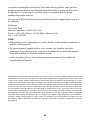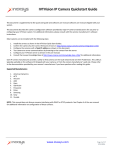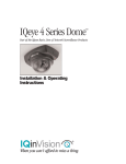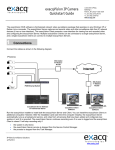
1
IQeye Alliance™ Series
Vandal-Resistant IP Camera
Installation and Operating Instructions
®
When you can’t afford to miss a thing.
Important Safeguards
CAUTION
RISK OF ELECTRIC
SHOCK. DO NOT OPEN!
CAUTION: BEWARE OF RISK OF ELECTRICAL SHOCK.
REFER SERVICING TO QUALIFIED SERVICE PERSONNEL.
Due to product size and space limitations, this label may not appear on all products.
The lightning flash with an arrowhead symbol within an equilateral triangle is intended to
alert the user to the presence of uninsulated “dangerous voltage” within the product’s enclosure
that may be of sufficient magnitude to constitute a risk of electric shock to persons.
The exclamation point within an equilateral triangle is intended to alert the user to
presence of important operating and maintenance (servicing) instructions in the literature
accompanying the appliance.
WARNING: TO PREVENT FIRE OR SHOCK HAZARD,
DO NOT EXPOSE UNITS TO RAIN OR MOISTURE.
Attention: Installation should be performed by qualified service personnel only in accordance
with the National Electrical Code or applicable local codes.
2
2
Contents
1. Unpacking................................................................................................................. 3
2. Service........................................................................................................................ 3
3. Description................................................................................................................. 4
4. Installation................................................................................................................ 4
5. Parts List.................................................................................................................... 4
6. Mounting Options...................................................................................................... 5
7. Removal of Dome Cover and Camera Assembly....................................................... 6
8. Install Mounting Plate.............................................................................................. 6
9. Connect Camera........................................................................................................ 7
10. Camera Positioning, Field-of-View Set-up and Focus............................................ 7
11. Reboot and Factory Restore..................................................................................... 8
12. Close Camera........................................................................................................... 9
13. PC Configuration..................................................................................................... 9
14. Warranty................................................................................................................ 10
1. Unpacking
Unpack carefully. This is an electromechanical device and should be handled
carefully. Check to ensure the following items are included:
• Alliance Dome Camera assembly
• Torx T-20 security wrench
• Mounting template
• Mounting hardware
• IQtools CD-ROM
2. Service
If the unit needs repair service or parts, the customer should contact IQinVision for
authorization to return, as well as shipping instructions.
IQinVision
33122 Valle Road
San Juan Capistrano, CA 92675-4853
Phone: +1-949-369-8100 or 1-877-850-0805 (toll-free in U.S.)
Fax: +1-949-369-8105
3
3. Description
IQeye Alliance Series is an advanced network mini-dome camera available in
multiple resolutions from VGA to multi-megapixel. Alliance’s unique auto-tracking
shroud automatically aligns during setup and installation of the camera, and its
innovative low-profile design gives a flush-mount appearance though Alliance is
actually a surface mount camera. Alliance’s mounting plate provides for a stable,
robust installation, and the integrated 3-axis gimbal allows you to mount Alliance
anywhere and still achieve level, high-quality images.
The IQeye Alliance is fully vandal-resistant, with a housing constructed of highgrade aluminum and a dome bubble constructed of polycarbonate material.
4. Installation
NOTE: This manual describes how to install the IQeye Alliance Series camera
system, and details wall and ceiling mounting options. Installations should be
performed by qualified service personnel only in accordance with local, state
and national code(s).
5. Parts List
Figure 5.1 depicts the major camera assembly
parts included:
1. Alliance Mounting Plate
2. Alliance Camera, Lens, and Shroud Assembly
3.
2.
3. Alliance Dome Cover Assembly
1.
Figure 5.1
4
6. Mounting Options
Alliance can be mounted in one of two configurations, wall
or ceiling. Both mounting configurations are shown in
Figures 6.1 and 6.2.
In the wall mount configuration, you can use the 3-axis
gimbal to level the field of view for any camera position.
In any configuration, Alliance comes with multiple
connection options based on the individual needs of the
application. The different connectors shown in Figure 6.3
show all required and optional connections:
Figure 6.1
1. Ethernet / PoE cable (required)
2. Aux 12-24V DC power and terminal strip (optional)
3. BNC Analog Video out (optional)
Figure 6.2
4. Audio-in cable (H.264 variant)
5. Audio-out cable (H.264 variant)
Aux 12-24V DC power
and terminal strip
(optional)
Figure 6.3
5
7. Removal of Dome Cover and Camera
Assembly
1. U sing the supplied Torx T-20 security tool,
loosen the four screws holding the dome cover
to the rest of the Alliance camera assembly.
Note that these screws are captively held to the
dome cover and should not be removed from
the dome cover trim ring.
2. O nce loosened, lift the dome cover and trim
ring away from the camera assembly.
3. L ocate the removal tabs where the camera
assembly connects to the mounting plate as
shown in Figure 7.1.
Removal Tabs
Figure 7.1
4. P ress any two of the three removal tabs and pivot the camera assembly up and
away from the mounting plate. Carefully thread the connection cables out
through the mounting plate hole.
8. Install Mounting Plate
1. P osition the supplied mounting template on the surface in the location where the
camera will be installed. Trace and drill the mounting holes and the cable pass
through hole as indicated.
2. U sing the supplied hardware, or equivalent hardware, install the mounting plate
to the intended surface.
3. Pull cabling through the pass-through hole.
OTE: If you are installing your Alliance into a ceiling tile, please be sure to
N
use hardware designed to secure the camera assembly to such a surface, and
that the ceiling tile material being mounted is secure.
6
In addition possible local regulations and laws that may have specific
requirements governing the installation of security equipment on a ceiling tile
surface, IQinVision also strongly recommends the use of a ceiling tile brace and
other mounting hardware designed to secure your Alliance to the ceiling frame
infrastructure.
9. Connect Camera
1. I f 12-24V DC or Input/Output connections are required, be sure to attach the
supplied male connector to the appropriate wiring coming from the head end.
2. C onnect Ethernet, aux power & I/O, and analog video out connections as
appropriate between the camera and the head end. If you are using 12-24V DC
power, pay careful attention to the polarity markings on the connector and make
sure they match the polarity of your power leads.
3. ( H.264 variant only) Connect audio cables to the supplied 3.5mm “Audio-in” and
“Audio-out” cables.
4. C arefully feed the connected wires one at a time back through the pass through
hole.
5. C arefully snap the camera assembly to the mounting ring by first sliding one of
the removal tabs under the attachment lip of the mounting ring then firmly pivot
the other two mounting tabs into the mounting plate. You should feel the camera
mount tabs snap into place.
10. C
amera Positioning, Field-of-View
Set-up and Focus
NOTE: Camera positioning, field-of-view and focus set-up can be assisted by
connecting an analog test monitor to the installation/set-up RCA port on the
side of the camera.
1. D etermine camera pan direction by gripping the camera assembly near the
mounting plate, carefully pivot the camera to the approximately correct pan
direction.
7
2. L ift open the camera shroud by flipping it down
and away from the front of the camera. The
front of the camera is indicated by the lens
location.
3.Adjust the tilt of the camera by loosening the tilt
angle lock screw as shown in Figure 10.1 and
pivoting the lens position to the desired range.
When finished, lock down the camera tilt angle
by tightening the tilt lock screw.
4. A djust the field-of-view and focus rings to
achieve the desired result. Be sure to lock the
lens ring thumbscrews by tightening them down.
Tilt Lock Mechanism
Figure 10.1
5. A lliance is equipped with a secondary analog video
port, RCA type, which can be found next to the reset/reboot buttons.  This analog
port utilizes IQinVision’s exclusive IQfocus utility which allows precise focusing of
the camera. Note that IQfocus shuts off 5 minutes after Alliance is powered up or
immediately after Alliance begins sending its digital stream.
NOTE: The B2/B3 lens on Alliance is fixed iris and therefore no iris adjustment
is needed.
11. Reboot and Factory Restore
ebooting - Depress the reboot key for 2 -3
R
seconds then release.
Restoring to Factory Default - While
pressing the “Factory” key, press and hold
the “Reboot” key for 2-3 seconds. Keep
holding the Factory key for 10 seconds,
then release.
Factory
Reboot
Figure 11.1
8
12. Close Camera
1. O nce field-of-view and focus have been verified, make sure all adjustment screws
and locks are firmly tightened.
2. R emove analog test monitor RCA connection (if used).
3. C lose shroud by pivoting it back against the camera, being careful not to brush
the lens.
4. C arefully position the dome cover so that the dome cover screws line up with the
matching receiving holes on the mounting plate.
5. Tighten the dome cover to the mounting plate with the supplied Torx T-20 tool.
13. PC Configuration of IQeye Alliance
PLEASE NOTE – The default user name for all IQeye devices is “root”
and the default password is “system.”
a) Insert the IQtools CD in the CD drive of the PC. The IQfinder installation
application will launch automatically. See Figure 13.1
Figure 13.1
b) Click the “Scan for IQeye cameras on my network” button to find
IQeye cameras. See Figure 13.2
c) The detected cameras will be displayed in the IQfinder window. Highlight
a camera from the list and click the “Edit” button to edit the selected
camera’s IP settings. See Figure 13.3
Figure 13.2
d) The Edit window allows the Name, IP address, Subnet, and Gateway of
the camera to be changed. It also allows the camer to be configured
to DHCP. Click the “Apply” button after making the desired changes.
See Figure 13.4
Note: Changing between a static IP address and DHCP will
require the camera to be rebooted.
Figure 13.3
e) To view a camera, double-click on a camera entry in the list, highlight the
camera and click the “Open” button. The “Live’ page will be displayed.
NOTE: It’s also possible to open Internet Explorer, then enter the IP address
of the IQeye device in the address field of the browser.
Figure 13.4
9
14. I QinVision 2 YEAR LIMITED
HARDWARE WARRANTY
Warranty Coverage
IQinVision, Inc. (“IQinVision”) warranty obligations are limited to the terms set forth below:
IQinVision warrants the original purchaser that the IQINVISION Network Video product
enclosed with this limited hardware warranty will in respect of the hardware be free from
defects in design, workmanship and materials under normal use for a period of two (2)
years from the date of the original end-user purchase (“Warranty Period”).
The original purchaser shall without undue delay notify IQinVision of any defect which
appears according to IQinVision’s RMA Handling procedure, failure to which shall mean
that the purchaser loses its right to have the defect remedied. A valid form of a bill of sale or
receipt from an authorized retailer/distributor with the date of the original purchase must be
presented to obtain warranty service. If a valid claim is received within the Warranty Period,
the sole remedy of the original purchaser and IQinVision’s sole and exclusive liability shall
be limited to, at IQinVision’s sole discretion, IQinVision will repair or replace defective
parts of the IQeye camera with new parts, or with serviceable used parts that are superior
or equivalent in performance to new parts, without charge. Repaired or replacement
hardware will be warranted for the remainder of the original Warranty Period or ninety (90)
days, whichever is longer. When a product or part is exchanged the replacement hardware
becomes the property of the original purchaser and all hardware or part thereof that is
replaced shall become the property of IQinVision.
This Limited Warranty is applicable in all countries and may be enforced by contacting
IQinVision support worldwide, for more information please visit our web site www.iqeye.com
Exclusions and Limitations
This warranty does not apply (a) to faulty and improper installation, maintenance, service,
repair and/or alteration in any way that is not contemplated in the documentation for the
product or carried out with IQinVision’s consent in writing, operational adjustments covered
in the operating manual for the product or normal maintenance, (b) to cosmetic damages,
(c) if the product is modified or tampered with, (d) if the product is damaged by acts of
God, accident, normal wear and tear and deterioration, improper environmental conditions
(including, but not limited to, electrical surges, water damage, chemical exposure, and/or
heat/cold exposure) or lack of responsible care, (e) if the product has had the model or
serial number altered, defaced or removed, (f) to consumables (such as storage media or
batteries) (g) to products that have been purchased “as is” and IQinVision, the seller or the
liquidator expressly disclaim their warranty obligation pertaining to the product, misuse,
abuse, negligence, (h) to any non-IQinVision hardware product or any software
10
(irrespective of packaged or sold with an IQinVision hardware product) and IQinVision
products purchased from an unauthorized distributor/reseller,(i) to damage that occurs
in shipment or (j) to damages by any other causes not related to defective design,
workmanship and/or materials.
All Inquiries for RMA and Warranty Repair should be directed to [email protected] or to
the following:
IQinVision
33122 Valle Road
San Juan Capistrano, CA 92675-4853 USA
Phone: +1-949-369-8100 or 1-877-850-0805 (toll-free in U.S.)
Fax: +1-949-369-8105
NOTE:
• If the product is to be used outdoors or in dusty, humid, or other hostile environments, it
must be suitably protected.
• For camera products supplied without a lens, extreme care should be used when
mounting a lens on these products. Damage to the product due to incorrectly mounted
lenses will invalidate this limited hardware warranty.
• Failure to comply with any of the aforementioned requirements will invalidate this
Limited Hardware Warranty.
THE WARRANTY AND REMEDIES PROVIDED ABOVE ARE EXCLUSIVE AND IN LIEU OF ALL OTHER EXPRESS OR IMPLIED
WARRANTIES INCLUDING, BUT NOT LIMITED TO, THE IMPLIED WARRANTIES OF MERCHANTABILITY OR FITNESS FOR
A PARTICULAR PURPOSE. CERTAIN JURISDICTIONS DO NOT ALLOW THE EXCLUSION OF IMPLIED WARRANTIES. IF LAWS
UNDER SUCH JURISDICTIONS APPLY, THEN ALL EXPRESS AND IMPLIED WARRANTIES ARE LIMITED TO THE WARRANTY
PERIOD IDENTIFIED ABOVE. UNLESS PROVIDED HEREIN, ANY STATEMENTS OR REPRESENTATIONS MADE BY ANY OTHER
PERSON OR FIRM ARE VOID. EXCEPT AS PROVIDED IN THIS WRITTEN WARRANTY AND TO THE EXTENT PERMITTED
BY LAW, NEITHER IQINVISION NOR ANY AFFILIATES SHALL BE LIABLE FOR ANY LOSS, (INCLUDING LOSS OF DATA AND
INFORMATION), INCONVENIENCE, OR DAMAGE, INCLUDING, BUT NOT LIMITED TO, DIRECT, SPECIAL, INCIDENTAL OR
CONSEQUENTIAL DAMAGES, RESULTING FROM THE USE OR INABILITY TO USE THE IQINVISION PRODUCT, WHETHER
RESULTING FROM BREACH OF WARRANTY OR ANY OTHER LEGAL THEORY. NOTWITHSTANDING THE FOREGOING,
IQINVISION’ TOTAL LIABILITY FOR ALL CLAIMS UNDER THIS WARRANTY SHALL NOT EXCEED THE PRICE PAID FOR
THE PRODUCT. THESE LIMITATIONS ON POTENTIAL LIABILITIES HAVE BEEN AN ESSENTIAL CONDITION IN SETTING
THE PRODUCT.
11
When you can’t afford to miss a thing.
®
www.iqeye.com
901-0046 Rev A.1
33122 Valle Road
San Juan Capistrano, CA 92675-4853 USA
phone +1.949.369.8100
fax +1.949.369.8105