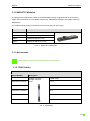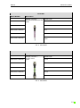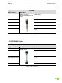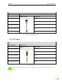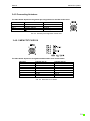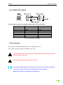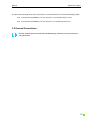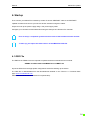
1
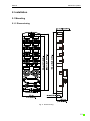
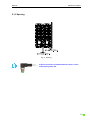
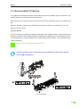
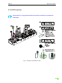
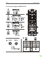
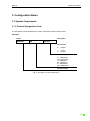
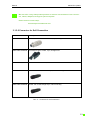
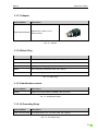
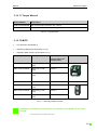
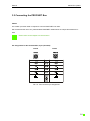
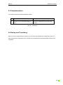
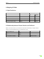
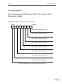
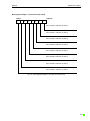
|Manual IMPACT67-PNIO | Installation | Configuration Notes | Startup | Mapping I/O Data | Diagnostics | Technical Data Manual IMPACT67 | PNIO Publisher's Note User Manual for IMPACT67 PN DI16 (Article Number: 55091) IMPACT67 PN DI8 DO8 (Article Number: 55092) IMPACT67 PN DO8 (Article Number: 55093) IMPACT67 PN DO16 (Article Number: 55094) Version 1.4 Edition 08_12 DE Article Number 55366 Murrelektronik GmbH Falkenstrasse 3 D-71570 Oppenweiler Tel +49 (0) 71 91 47-0 Fax +49 (0) 71 91 47-130 [email protected] 2 Manual IMPACT67 | PNIO Service and Support Website: www.murrelektronik.com In addition, our Customer Service Center (CSC) will be glad to assist you: Our Customer Service Center can support you throughout your project: planning and the conception of customer applications, configuration, installation, and startup. We also offer competent consulting or – in more complex cases – we even provide direct onsite support. The Customer Service Center provides support tools. It performs measurements for fieldbus systems, such as PROFIBUS DP, DeviceNet, CANopen, and AS interface, as well as energy, heat, and EMC measurements. Our coworkers at the Customer Service Center provide their competence, know-how, and years of experience. They are knowledgeable about hardware and software, and compatibility with products made by various manufacturers. You can contact the Customer Service Center at telephone number +49 (0) 71 91 47-424 or by email at [email protected]. 3 Manual IMPACT67 | PNIO About the User Manual and its Structure 4 Manual IMPACT67 | PNIO Here are links to the bus user manuals: >>> PROFINET (www.profinet.com) 5 Manual IMPACT67 | PNIO Table of Contents Publisher's Note ...................................................................................................................................... 2 Service and Support ................................................................................................................................ 3 About the User Manual and its Structure ................................................................................................ 4 Table of Contents .................................................................................................................................... 6 Important Information .............................................................................................................................. 9 1. Description of IMPACT67 .................................................................................................................. 11 2. Installation ......................................................................................................................................... 12 2.1 Mounting ...................................................................................................................................... 12 2.1.1 Dimensioning ........................................................................................................................ 12 2.1.2 Spacing ................................................................................................................................. 13 2.1.3 Mounting IMPACT67 Modules .............................................................................................. 14 2.1.4 IP67 Protection ...................................................................................................................... 15 2.2 Connection Diagram of IMPACT67 PN ....................................................................................... 16 3. Configuration Notes ........................................................................................................................... 17 3.1 System Components ................................................................................................................... 17 3.1.1 Product Designation Code .................................................................................................... 17 3.1.2 IMPACT67 Modules .............................................................................................................. 18 3.1.3 Accessories ........................................................................................................................... 18 3.2 Connecting the PROFINET Bus .................................................................................................. 26 3.3 Power Supplies ............................................................................................................................ 28 3.4 Connecting Sensors and Actuators ............................................................................................. 31 3.4.1 Connecting Sensors .............................................................................................................. 31 3.4.2 Connecting Actuators ............................................................................................................ 33 3.5 Unused Connections ................................................................................................................... 35 4. Startup ............................................................................................................................................... 36 4.1 GSD File ...................................................................................................................................... 36 4.2 Configuration with S7 Hardware Manager ................................................................................... 37 4.2.1 General Information .............................................................................................................. 37 6 Manual IMPACT67 | PNIO 4.2.2 Calibrating the IMPACT67 .................................................................................................... 38 4.2.3 Setting the Topology ............................................................................................................. 40 4.2.4 Identifying Individual Devices in the Network........................................................................ 41 4.2.5 Issuing Device Names and IP Addresses ............................................................................. 42 4.3 Parameterization .......................................................................................................................... 43 4.4 Saving and Translating ................................................................................................................ 43 5. Mapping I/O Data .............................................................................................................................. 44 5.1 Byte Distribution ........................................................................................................................... 44 5.2 Relationship between Channel Number and Pin/Socket ............................................................. 44 5.3 Bit Assignment ............................................................................................................................. 45 5.3.1 Bit assignment for DO8 (Art.No.: 55093) / DI16 (Art.No.: 55091) / DO16 (Art.No.: 55094) . 45 5.3.2 Bit assignment for DI8 DO8 (Art.No.: 55092)........................................................................ 47 6. Diagnostics ........................................................................................................................................ 49 6.1 LED Displays ............................................................................................................................... 49 6.1.1 Bus and Device Status LEDs ................................................................................................ 49 6.1.2 I/O Status LEDs at M12 Slots ............................................................................................... 52 6.1.3 LED Display for Diagnostics.................................................................................................. 53 6.2 Module / Sensor Power Supply ................................................................................................... 55 6.2.1 Undervoltage ......................................................................................................................... 55 6.3 Actuator Power Supply ................................................................................................................ 55 6.3.1 Undervoltage ......................................................................................................................... 55 6.4 Sensor Power Supply .................................................................................................................. 56 6.4.1 Short-Circuit or Overload ...................................................................................................... 56 6.5 Outputs (Actuators) ...................................................................................................................... 57 6.5.1 Short-Circuit or Overload ...................................................................................................... 57 6.6 Diagnostics via the Fieldbus ........................................................................................................ 58 7. Technical Data................................................................................................................................... 59 7.1 Art. No. 55091 IMPACT67 PN DI16 ............................................................................................ 59 7.2 Art. No. 55092 IMPACT67 PN DI8 DO8 ...................................................................................... 61 7.3 Art. No. 55093 IMPACT67 PN DO8............................................................................................. 63 7 Manual IMPACT67 | PNIO 7.4 Art. No. 55094 IMPACT67 PN DO16........................................................................................... 65 Abbreviations ......................................................................................................................................... 67 Legal Provisions .................................................................................................................................... 69 8 Manual IMPACT67 | PNIO Important Information Symbols and Icons This manual contains information and instructions you must comply with in order to maintain safety and avoid personal injury or damage to property. They are identified as follows: Notes indicate important information. Warnings contain information that, if you ignore this information, may cause damage to equipment or other assets or, if you fail to comply with safety precautions, may constitute a danger to the user's health and life. These instructions are recommendations issued by Murrelektronik. Intended Purpose Before starting the devices, read this manual carefully. Keep it in a location that is accessible to all users at all times. The products that are described in this manual were developed, manufactured, tested, and documented in compliance with the relevant safety standards. In normal cases, these products do not constitute any danger to persons or objects, provided the handling specifications and safety instructions described in this manual are observed. They conform to the requirements of • EMC Directive (2004/108/EC) The products are designed for industrial use. An industrial environment is defined as one in which loads are not connected directly to the public low-voltage power grid. Additional measures must be taken if the products are used in private, business, or trade environments. The safe, troublefree functioning of the products requires proper transportation, storage, mounting, and installation, and careful operation. Operation of the devices for their intended purposes is only guaranteed when the enclosures are fully mounted. If aggressive media are used, check their material resistance depending on the application. Current safety and accident prevention laws valid for a specific application must be observed for the configuration, installation, setup, maintenance, and testing of the devices. The power supply must 9 Manual IMPACT67 | PNIO comply with SELV or PELV. Power sources in accordance with EN 61558-2-6 (transformer) or EN 60950-1 (switched-mode power supply) meet these requirements. Only use cables that meet the requirements and regulations for safety, electromagnetic compatibility, and, if necessary, telecommunications terminal equipment specifications. Information on the cables and accessories that are suitable for use with this product are contained in the Section 3.1 of this manual. Qualified Personnel Only qualified, trained electricians knowledgeable in the safety standards of automation systems may configure, install, set up, maintain, and test the devices. The requirements concerning qualified personnel are dependent on the requirements profiles described in ZVEI and VDMA. For this reason, electricians must know the contents of the manual "Weiterbildung in der Automatisierung" (Further Training in Automation Systems) published by ZVEI and VDMA published by Maschinenbau-Verlag, Post Box 710864, 60498 Frankfurt, Germany) before installing and maintaining the devices. They are therefore electricians who are capable of assessing the work executed and any possible dangers arising from this due to their professional training, knowledge, experience, and their knowledge of the pertinent standards; or who have a level of knowledge equivalent to professional training due to their many years of activity in a comparable field. Only Murrelektronik technical personnel are allowed to execute work on the hardware and software of our devices, if they are devices not described in this manual. Unqualified tampering with the hardware or software, or failure to observe the warnings cited in this manual may result in severe personal injury or damage to property. 10 Manual IMPACT67 | PNIO 1. Description of IMPACT67 Fieldbus modules with IP67 protection are an important module in machine installation and they replace complex wired, and therefore, high-cost terminal boxes. Fieldbuses replace conventional parallel wiring. An increase in efficiency in installation systems was the prime motivator in developing the IMPACT67. Concentration on what is important, coupled with purposeful connectivity, is our recipe for success to reduce your installation costs. • Application-specific: compact and dense • Installation-friendly: well designed and pluggable • Economic: minimized to what is important System Design Principle Fig. 1: System design principle 11 Manual IMPACT67 | PNIO 2. Installation 2.1 Mounting 2.1.1 Dimensioning Fig. 2: Dimensioning 12 Manual IMPACT67 | PNIO 2.1.2 Spacing Fig. 3: Spacing Angled connectors from Murrelektronik require a minimum spacing of 50 mm. 13 Manual IMPACT67 | PNIO 2.1.3 Mounting IMPACT67 Modules The modules of the IMPACT67 Series can be fitted directly to an installation panel or a machine. The module features two mounting holes for this purpose. Make sure that the mounting surface is flat and level to prevent mechanical stress in the module housing. Attach the module using two 6 mm diameter screws and two washers as per DIN 433 T1/T2. The tightening torque is 3 Nm. Function Ground The FE connection is located at the bottom facing edge of the module housing. To ensure proper functioning in compliance with the EMC regulations specified in the datasheet, we recommend the use of our grounding strap. It is not included in the as-delivered state of the module. You must therefore purchase it separately. Please refer to the chapter on Accessories. Connect the PE terminal on the housing at low impedance to the function ground (refer to EMC information). Fig. 4: Mounting 14 Manual IMPACT67 | PNIO 2.1.4 IP67 Protection IP67 protection is only guaranteed when all sockets are wired up or provided with blank plugs. Fig. 5: Example of assembly for IP67 15 Manual IMPACT67 | PNIO 2.2 Connection Diagram of IMPACT67 PN 16 Manual IMPACT67 | PNIO 3. Configuration Notes 3.1 System Components 3.1.1 Product Designation Code The designation format of IMPACT67 system components explains their function. Examples: Name IMPACT67 Description PN DI8 DO8 I/O channels D = Digital I O = Input = Output Fieldbus System P = PROFIBUS DN = DeviceNet C = CANopen EC = EtherCat E = EtherNet/IP PN = PROFINET Product Family Fig. 6: Example of product designation 17 Manual IMPACT67 | PNIO 3.1.2 IMPACT67 Modules The purpose of the IMPACT67 system is the decentralized routing of signals at the I/O level and the supply of this information over a Fieldbus network (e.g. PROFIBUS, CANopen, DeviceNet, EtherCAT, EtherNet/IP). The module and I/O units are powered by a 5-pin power plug 7/8" (mini style). Article Number Description 55091 IMPACT67 PN DI16 55092 IMPACT67 PN DI8 DO8 (2A) 55093 IMPACT67 PN DO8 (2A) 55094 IMPACT67 PN DO16 (0,5A) Tab. 1: IMPACT67 PN Modules 3.1.3 Accessories Most cables and connectors are available in angled style. 3.1.3.1 BUS Cables PROFINET Article Number Description 7000-44511-7980150 Straight connector / straight connector violet Cable length 1.5 m 7000-44511-7980300 3m 7000-44511-7980500 5m 7000-44511-7980750 7.5 m 7000-44511-7981000 10 m Tab. 2: PROFINET 18 Manual IMPACT67 | PNIO PROFINET Article Number Description 7000-14541-7980150 Straight connector with nonterminated wire end violet Cable length 1.5 m 7000-14541-7980300 3m 7000-14541-7980500 5m 7000-14541-7980750 7.5 m 7000-14541-7981000 10 m Tab. 3: PROFINET PROFINET Article Number Description 7000-44511-7960150 Straight connector / straight socket green Cable length 1.5 m 7000-44511-7960300 3m 7000-44511-7960500 5m 7000-44511-7960750 7.5 m 7000-44511-7961000 10 m Tab. 4: PROFINET 19 Manual IMPACT67 | PNIO PROFINET Article Number Description 7000-14541-7960150 Straight connector with nonterminated wire end green Cable length 1.5 m 7000-14541-7960300 3m 7000-14541-7960500 5m 7000-14541-7960750 7.5 m 7000-14541-7961000 10 m Tab. 5: PROFINET 3.1.3.2 POWER Cables Power cable 7/8“ Article Number 7000-50021-9610030 Description Straight connector / straight socket Cable length 0.3 m 7000-50021-9610060 0.6 m 7000-50021-9610100 1m 7000-50021-9610150 1.5 m 7000-50021-9610200 2m Tab. 6: Power cable 7/8“ 20 Manual IMPACT67 | PNIO Power cable 7/8“ Article Number 7000-78021-9610150 Description Straight socket / with nonterminated wire end Cable length 1.5 m 7000-78021-9610300 3m 7000-78021-9610500 5m 7000-78021-9610750 7,5 7000-78021-9611000 10 m Tab. 7: Power cable 7/8“ 3.1.3.3 I/O Cables I/O Article Number Description 7000-12041-0250150 Straight connector yellow with nonterminated wire end Cable length 1.5 m 7000-12041-0250300 3m 7000-12041-0250500 5m 7000-12041-0250750 7.5 m 7000-12041-0251000 10 m Tab. 8: I/O The input/output cables are of course available in all shapes, colors, and combinations. 21 Manual IMPACT67 | PNIO 3.1.3.4 Valve Connector Combination Style A • Contact spacing 18 mm • Operating voltage 24 V AC/DC • Operating current max. 4 A Article Number Description M12 top connection Cable length 7000-41501-2260000 110 mm 7000-41521-2260000 150 mm 7000-41541-2260000 200 mm M12 rear connection Cable length 7000-41561-2260000 110 mm 7000-41581-2260000 150 mm 7000-41601-2260000 200 mm Other system accessories on request Tab. 9: Valve connector combination Style A 3.1.3.5 Valve Connector Style A • Contact spacing 18 mm • Operating voltage 24 V AC/DC, pressure switch 24 V DC • Operating current max. 4 A Article Number Description 7000-41341-0000000 M12 top connection 7000-41361-0000000 7000-41461-0000000 7000-41481-0000000 LED yellow, protection circuit for valves LED yellow/green for pressure switch M12 rear connection LED yellow, protection circuit for valves LED yellow/green for pressure switch Tab. 10: Valve connector Style A 22 Manual IMPACT67 | PNIO We also offer a very wide product portfolio of sensors and actuators. From connectors, cables, adapters, through to special requests. Please visit our online shop: onlineshop.murrelektronik.com 3.1.3.6 Connector for Self-Connection Article Number Description 7000-14521-0000000 CAT5 Bus M12 connector D-coded, 4-pin, straight 7000-99051-0000000 CAT5 Bus RJ45 D-coded, 4-pin, straight IP20 7000-00000-7969999 Bus cable for PROFINET, 100 m collar 7000-78081-0000000 Power 7/8“ straight connector 5-pin, self-connecting 7000-78201-0000000 Power 7/8" socket straight 5-pin, self-connecting Tab. 11: Connector for self-connection 23 Manual IMPACT67 | PNIO 3.1.3.7 Adapter Article Number Description 7000-99052-0000000 Adapter M12 / RJ45, CAT 5, Socket /socket Tab. 12: Adapter 3.1.3.8 Blank Plug Article Number Description 7000-41241-0000000 M12 diagnostic adapter (for line monitoring to bridges) 58 627 M12 plastic plug (SP 10 pieces) 338155 Diagnosis blanking plug M12x1 (VP 1 pc.) 55390 7/8'' screw plug, metal with chain (SP 1 piece) 55385 7/8'' screw plug, plastic (SP 1 piece) Tab. 13: Blank plug 3.1.3.9 Identification Labels Article Number Description 996067 IDENTIFICATION LABELS 20X8MM (SP 10 pieces) Tab. 14: Identification labels 3.1.3.10 Grounding Strap Article Number Description 4000-71001-0410004 Grounding strap 4 mm² 100 mm for M4 (SP 1 piece) Tab. 15: Grounding strap 24 Manual IMPACT67 | PNIO 3.1.3.11 Torque Wrench Article Number Description 7000-99102-0000000 Set of M12 torque wrenches (SP 1 piece) 7000-99104-0000000 Set of 7/8" torque wrenches (SP 1 piece) Tab. 16: Torque wrench 3.1.3.12 MICO • – Fire protection (EN 60950-1) • – Operating voltage protection (EN 61131-2) • – Operating state memory device (EN 61131-1) Article Number Description Nominal operating branch-circuit current (full load) 9000-41034-0100400 MICO 4.4 (4 channels) each 4 A 9000-41034-0100600 MICO 4.6 (4 channels) each 6 A 9000-41034-0401000 MICO 4.10 (4 channels) each 10 A 9000-41042-0100400 MICO 2.4 (2 channels) each 4 A 9000-41042-0100600 MICO 2.6 (2 channels) each 6 A 9000-41042-0401000 MICO 2.10 (2 channels) each 10 A Tab. 17: Overview of MICO variants Information on products and accessories are available in our catalog and our online shop at: onlineshop.murrelektronik.com 25 Manual IMPACT67 | PNIO 3.2 Connecting the PROFINET Bus Cables A D-coded 4-pin M12 cable is required to connect PROFINET bus users. We recommend the use of our preterminated PROFINET cables which are simple and reliable to install. Please refer to the chapter on Accessories. Pin assignment for bus terminal M12, 4-pin (D-coded) socket socket Tab. 18: Bus connector pin assignment 26 Manual IMPACT67 | PNIO Make-up of PROFINET round cable Fig. 7: PROFINET round cable 1 Sheath 4 bus conductor, white (RD+) 2 Line shield 5 bus conductor, yellow (TD+) 3 Central filler 6 bus conductor, orange (TD-) 7 Bus conductor,, blue (RD-) Cables (PROFINET Bus Cable) violet or green Conductors (PROFINET bus cable) white - fieldbus system cable (RD+) blue - fieldbus system cable (RD-) yellow - fieldbus system cable (TD+) orange - fieldbus system cable (TD-) Connecting to IMPACT67 1. Mounting the IMPACT67 module. 2. Connect function ground to FE terminal on housing. 3. Connect incoming bus cables. 4. Connect any outgoing bus cable. 27 Manual IMPACT67 | PNIO 3.3 Power Supplies We recommend the use of primary switched-mode power supplies in applications with the IMPACT67 and to supply the sensors and actuators. IMPACT67 modules require a DC power supply in the range 18 to 30 V. It is recommended to take different power supplies to power the sensors and actuators in order to achieve greater immunity from interference and decoupling. System-related limit values regarding system power supply must be strictly observed if maximum functional safety and fault-free operation are to be ensured. Always ensure that the system power, measured at the device furthest from the power supply, does not drop below 18 VDC. A load current-related voltage drop in the power supply cable occurs due to the central power supply of IMPACT67 modules, including all their connected sensors. In critical cases, voltage drop optimization is obtainable by changing the location of the power supply unit within the overall system and by using power supply cables with a larger conductor cross-section. Calculating the required conductor cross-sections is dependent on installationspecific configuration data and is therefore not discussed in this manual. The power supply module may be damaged if power supply is polarity-reversed. For this reason, we recommend the use of our preterminated 7/8" cables. 28 Manual IMPACT67 | PNIO 3.3.1.1 Connecting the Power Supply to the Module The auxiliary power is required to power the actuators and sensors. The electronics of the IMPACT67 are powered from the sensor power supply. The 7/8“ connector is designed to carry a maximum current of 9 A per pin. This is taken into account when connecting the power supply to another circuit. Power Supply Line Module supply cables must have VDE approval and a maximum core cross-section of 1.5 mm². All further power supply line characteristics depend on individual applications and are not covered in this manual. The maximum permitted core cross-section is 1.5 mm². Pin assignment of 5-pin power plug 7/8" (mini style) Connector Socket Tab. 19: Pin assignment of power plug 7/8" (mini style) 29 Manual IMPACT67 | PNIO Cable assignment of 5-pin power cable Conductors (power cable) Black conductors 1 0V Black conductors 2 0V green/yellow FE Black conductors 3 sensor and bus supply Black conductors 4 actuator power supply Connection to IMPACT67 1. Mounting the IMPACT67 module. 2. Attach function ground cable to IMPACT67 module. 3. Connect sensor/actuator level. 4. Hook up bus connection. 5. Connect power supply. Never switch off the sensor power supply (Pin 4) at the power supply connector in service and do not route via the emergency off circuits. Otherwise, the IMPACT67 module can no longer participate in bus communication. Therefore, the module electronics, the entire I/O section, and the sensors are powered via Pin 4. The actuator power supply (Pin 5) may be designed for EMERGENCY OFF circuits. 30 Manual IMPACT67 | PNIO 3.4 Connecting Sensors and Actuators 3.4.1 Connecting Sensors The table below depicts all the general pin assignments for the M12 socket slots Pin 1 Pin 2 Pin 3 Pin 4 Pin 5 + 24 V Function channel 0V Function channel Sensor supply Channel Reference potential Channel Function ground Tab. 20: General pin assignment of M12 slots 3.4.1.1 IMPACT67 PN DI16 The table below depicts the assignment between M12 slots and I/O labels. M12 slot 0 1 2 3 4 5 6 7 Channel (Pin 4) DI 00 DI 01 DI 02 DI 03 DI 04 DI 05 DI 06 DI 07 Channel (Pin 2) DI 10 DI 11 DI 12 DI 13 DI 14 DI 15 DI 16 DI 17 Tab. 21: M12 slots to I/O labels 31 Manual IMPACT67 | PNIO 3.4.1.2 IMPACT67 PN DI8 DO8 The table below depicts the assignment between M12 slots and I/O labels. M12 slot 0 1 2 3 4 5 6 7 Channel (Pin 4) DO 00 DO 01 DO 02 DO 03 DI 00 DI 01 DI 02 DI 03 Channel (Pin 2) DO 04 DO 05 DO 06 DO 07 DI 04 DI 05 DI 06 DI 07 Tab. 22: M12 slots to I/O labels 3.4.1.3 Sensor Power Supply Sensors can be powered directly via pins 1 (+24 V) and 3 (0 V) of the M12 sockets. The sensor power supply is protected per M12 slot. This protection is always self-resetting. The maximum current for the sensor power supply is 200 mA per M12 slot. Note the derating in the drawing below: Derating Sensor Power Supply Fig. 8: Derating sensor power supply IMPACT67 modules may be loaded to max. 200 mA per M12 slot (sensor current). 32 Manual IMPACT67 | PNIO 3.4.2 Connecting Actuators The table below depicts all the general pin assignments for the M12 socket slots Pin 1 Pin 2 Pin 3 Pin 4 Pin 5 n.c. Function channel 0V Function channel not connected Channel Reference potential Channel Function ground Tab. 23: General pin assignment of M12 slots 3.4.2.1 IMPACT67 PN DO16 The table below depicts the assignment between M12 slots and I/O labels. M12 slot 0 1 2 3 4 5 6 7 Channel (Pin 4) DO 00 DO 01 DO 02 DO 03 DO 04 DO 05 DO 06 DO 07 Channel (Pin 2) DO 10 DO 11 DO 12 DO 13 DO 14 DO 15 DO 16 DO 17 Tab. 24: M12 slots to I/O labels 33 Manual IMPACT67 | PNIO 3.4.2.2 IMPACT67 PN DO8 The table below depicts the assignment between M12 slots and I/O labels. M12 slot 0 1 2 3 4 5 6 7 Channel (Pin 4) DO 00 DO 01 DO 02 DO 03 DO 04 DO 05 DO 06 DO 07 Channel (Pin 2) DO 01 DO 03 DO 05 DO 07 - Tab. 25: M12 slots to I/O labels 3.4.2.3 Actuators Each output of the DO8 and DI8/DO8 variants is loadable to max. 2 A. Each output of the DO16 variant is loadable to max. 0.5 A. The total current may not exceed 9 A due to the maximum current carrying capacity of the 7/8“ power connector. The module may heat up depending on the load. If an output channel detects an overload or a short-circuit, the output is shut down. To reset the output, it must first be reset using the control software. Outputs are reset by an actuator power supply reset. 34 Manual IMPACT67 | PNIO In order to achieve rapid short-circuit cutoff times, we recommend not to exceed the following lengths: max. 15 m feed line (POWER IN) 1.5 mm² and max. 1.5 m actuator line 0.75 mm² max. 10 m feed line (POWER IN) 1.5 mm² and max. 3 m actuator line 0.75 mm² 3.5 Unused Connections Unused sockets must be closed off with blank plugs. Otherwise, IP 67 protection is not guaranteed. 35 Manual IMPACT67 | PNIO 4. Startup Then connect your IMPACT67 modules by means of an M12 PROFINET cable to an PROFINETcapable controller and connect your sensors and/or actuators using M12 cables. Only then hook up the power supply using a 7/8“ power supply cable. Configure your controller as described below using the example of a Siemens S7 controller. Prior to setup, a competent system structure check of the field bus must be assured. To start up, you require the latest version of the IMPACT67 GSD file. 4.1 GSD File The GDS file in GSDML format is required to operate the devices described in this manual. GSDML-Vx.x-Murrelektronik-IMPACT67-JJJJMMTT.xml Import the GSD file to the appropriate configuration tool before starting up the device. The GSD file is downloadable from the Murrelektronik website on the "Service >> Technical Data" page: www.murrelektronik.com. Please also download the associated icon Impact67.bmp. 36 Manual IMPACT67 | PNIO 4.2 Configuration with S7 Hardware Manager This chapter explains how to configure and parameterize an IMPACT67 module using the example of the HW configuration (hardware configuration software of the Simatic S7 Manager from Siemens). 4.2.1 General Information Configuring the PROFINET device is necessary to define the I/O data quantity and reserve the addresses in the controller. The IMPACT67 module is a physically compact device. However, in the PNIO system, it is treated as a modular system. This modular system comprises a "virtual" head module to which "virtual" useful data and "virtual" diagnostic modules are connected. First add the head module to the virtual bus, just as in a construction kit. Head modules always have zero data length and their function acts as module identification and parameterization. They are also in direct connection with the Article Number of each IMPACT67 module. A power supply module automatically follows each head module in Slot 1. The head module sends diagnostic messages to the power supplies. Then add the useful data modules. A separate address can be assigned to each of the useful data modules in the PLC process image. 37 Manual IMPACT67 | PNIO 4.2.2 Calibrating the IMPACT67 You can find the IMPACT67 under PROFINET IO “Other Field Devices” “I/O” in the Simatic Manager hardware catalog. Mark the appropriate “IMPACT67” in the hardware catalog and drag the entry to the virtual PROFINET line while holding down the left mouse button. 38 Manual IMPACT67 | PNIO After you add the required Impact67 to the PROFINET IO system, you can parameterize it. Parameterization takes place in Slot 0 via the virtual head module. Double-click to open the dialog box for module properties. Parameterize the module on the Parameters tab. For a detailed explanation of the meaning of these parameters, refer to Chapter 4.3 Parameterization. 39 Manual IMPACT67 | PNIO 4.2.3 Setting the Topology PROFINET offers a number of functions, diagnostic, and maintenance options based on the existing topology or utilizing knowledge of the topology. All IMPACT67 devices support the topology setting and automatic topology recognition by the Engineering Tool. This section briefly explains how to set up the topology for IMPACT67 modules. Setting up from connected adjacent devices is performed using Slots X1 P1 and X1 P2, which represent physical interfaces. A list of possible ports of other devices in the project are located on the Topology tab under the "Partner Port" option. 40 Manual IMPACT67 | PNIO 4.2.4 Identifying Individual Devices in the Network PNIO devices are identified by their MAC addresses and the appropriate device type. If you want to put several modules of the same type into operation, make sure you provide each with a definite unambiguous identification. Use your configuration tool to scan and select all the modules in the network. Use the path below to search the network for reachable users in the HW configuration: Target system Ethernet Edit Ethernet Users Search Identification takes place using the blink test. This test makes the LINK LED of the selected IMPACT67 device blink at a rate of 2 Hz. Mark an available device and select the Blink option. The IMPACT67 has the following factory settings: - MAC address: 00-0F-9E-xx-xx-xx - IP address: 0.0.0.0 - Device type: IMPACT67 - Device name: (empty) 41 Manual IMPACT67 | PNIO 4.2.5 Issuing Device Names and IP Addresses After you identify a module unambiguously, assign a device name to it. The IP address is issued automatically by the PNIO controller via DCP. The Simatic S7 Manager then shows you the data detected from the IMPACT67. Then set the required IP address and the subnet mask for use. Finally click on "Assign IP Configuration“. Alternatively, if you want to select the IP address automatically by DHCP Server, mark the suboption accordingly. With PROFINET IO, it is absolutely necessary to award a unique name for each device. The address and name resolution is only regulated using the name that is stored in a remanent memory in the device. After you have entered a name, please click on "Assign Name". The "Reset to Factory Settings" function clears the previous settings and restores the defaults. IP address: 0.0.0.0 Device name: (empty) 42 Manual IMPACT67 | PNIO 4.3 Parameterization This chapter explains the parameterization options. 1 Parameters Description Signal / do not signal global diagnostics Activates / deactivates all module diagnostics. Tab. 26: Parameters 4.4 Saving and Translating When you have configured all the modules, you can save and translate the configuration. After you have transferred the application to the controller, the configuration and parameterization features are completed. 43 Manual IMPACT67 | PNIO 5. Mapping I/O Data 5.1 Byte Distribution Header modules Number of output bytes Number of input bytes I/O Diagnostic IMPACT67 PN DI16, 55091 0 2 bytes 1 byte IMPACT67 PN DI8/DO8, 55092 1 byte 1 byte 3 bytes IMPACT67 PN DO8, 55093 1 byte 0 2 bytes IMPACT67 PN DO16, 55094 2 bytes 0 3 bytes 5.2 Relationship between Channel Number and Pin/Socket Based on the channel number, you can define the socket and the associated pin. Example: Channel number is 12, this corresponds to Pin 2 (x=1) of Socket No. 2 (Y=2). Channel number = XY X X=0 Pin 4 X=1 Pin 2 Y = 0 to (number of sockets) Y Number of sockets 44 Manual IMPACT67 | PNIO 5.3 Bit Assignment 5.3.1 Bit assignment for DO8 (Art.No.: 55093) / DI16 (Art.No.: 55091) / DO16 (Art.No.: 55094) Bit assignment Byte 0: relevant for DO8, DI16, DO16 Byte 0 7 6 Channel 5 4 3 2 1 0 M12 socket 0 channel 00 (Pin 4) M12 socket 1 channel 01 (Pin 4) M12 socket 2 channel 02 (Pin 4) M12 socket 3 channel 03 (Pin 4) M12 socket 4 channel 04 (Pin 4) M12 socket 5 channel 05 (Pin 4) M12 socket 6 channel 06 (Pin 4) M12 socket 7 channel 07 (Pin 4) Fig. 9: Bit assignment Byte 0: relevant for DO8, DI16, DO16 45 Manual IMPACT67 | PNIO Bit assignment Byte 1: relevant for DI16, DO16 Byte 1 7 6 Channel 5 4 3 2 1 0 M12 socket 0 channel 10 (Pin 2) M12 socket 1 channel 11 (Pin 2) M12 socket 2 channel 12 (Pin 2) M12 socket 3 channel 13 (Pin 2) M12 socket 4 channel 14 (Pin 2) M12 socket 5 channel 15 (Pin 2) M12 socket 6 channel 16 (Pin 2) M12 socket 7 channel 17 (Pin 2) Fig. 10: Bit assignment Byte 1: relevant for DO16, DI16 46 Manual IMPACT67 | PNIO 5.3.2 Bit assignment for DI8 DO8 (Art.No.: 55092) Bit assignment Byte 0: Outputs Byte 0 7 6 Channel 5 4 3 2 1 0 M12 socket 0 channel 00 (Pin 4) M12 socket 1 channel 01 (Pin 4) M12 socket 2 channel 02 (Pin 4) M12 socket 3 channel 03 (Pin 4) M12 socket 0 channel 10 (Pin 2) M12 socket 1 channel 11 (Pin 2) M12 socket 2 channel 12 (Pin 2) M12 socket 3 channel 13 (Pin 2) Fig. 11: Bit assignment Byte 0: Outputs 47 Manual IMPACT67 | PNIO Bit assignment Byte 1: Inputs Byte 1 7 6 Channel 5 4 3 2 1 0 M12 socket 4 channel 00 (Pin 4) M12 socket 5 channel 01 (Pin 4) M12 socket 6 channel 02 (Pin 4) M12 socket 7 channel 03 (Pin 4) M12 socket 4 channel 14 (Pin 2) M12 socket 5 channel 15 (Pin 2) M12 socket 6 channel 16 (Pin 2) M12 socket 7 channel 17 (Pin 2) Fig. 12: Bit assignment Byte 1: Inputs 48 Manual IMPACT67 | PNIO 6. Diagnostics Diagnostic information is an important basis for easy setup and quick troubleshooting. Clear information from the I/O module and its connected periphery components, such as sensors and actuators, identify, rectify, and therefore minimize downtimes. 6.1 LED Displays All IMPACT67 modules have separate and clearly arranged displays for bus status, device status, and I/O status displays. These displays are located on the front of the device. 6.1.1 Bus and Device Status LEDs The LEDs on the front of the module are clearly marked for identification. Display is provided by LEDs that light up permanently or flash. The figure below depicts LED layout and the table lists the functions. Fig. 13: Bus and device status LEDs on the module front panel 49 Manual IMPACT67 | PNIO When the IMPACT67 module is supplied with power, the device starts with an automatic self-test which takes about 2 seconds. Bus status LEDs on module front panel LED Designation LED Display Response Meaning RUN off Device is off RUN green Operational, device in service RUN green flashing No connection to controller ERR off Device operates faultfree ERR red Parameterization error L/A green Device detected a LINK L/A Green / yellow blinking LINK and Activity present (yellow blinking is normally perceived as permanent AN) Tab. 27: Bus status LEDs on module front panel 50 Manual IMPACT67 | PNIO Device status LEDs on the module front panel LED Description US POWER (red/green) UA POWER (red/green) LED Display Response Status Meaning off No voltage Failure of module and sensor power supply green voltage applied Module and sensor power supply applied red Undervoltage Module and sensor power supply undervoltage off No voltage Failure of actuator power supply green voltage applied Actuator supply OK red Undervoltage Undervoltage, actuator power supply Tab. 28: Device status LEDs on the module front panel 51 Manual IMPACT67 | PNIO 6.1.2 I/O Status LEDs at M12 Slots Each input and output is assigned a separate status display They are labeled with '00 to 07’ and '10 to 17’. The displays are located directly next to the corresponding M12 socket. This makes it easy to identify the status of peripheral components, such as sensors and actuators. LED Display of Digital Inputs Input with NO Contact Function Voltage at Input Logic Value LED Display 0V 0 off 24 V 1 yellow Tab. 29: LED display of digital inputs LED Display of Digital Outputs Output Logic Value Voltage at Output LED Display 0 0V off 1 24 V yellow Tab. 30: LED display of digital outputs 52 Manual IMPACT67 | PNIO 6.1.3 LED Display for Diagnostics 6.1.3.1 IMPACT67 DI16 Modules Error LED at M12 Socket LED Designation Socket No. x US Channel 0x Channel 1x Module/sensor power supply undervoltage Short-circuit (sensor supply) red both red Tab. 31: LED display for diagnostics 6.1.3.2 IMPACT67 DI8 DO8 Modules Error LED at M12 Socket LED Designation Socket No. x UA Channel 0x US Channel 1x Module/sensor power supply undervoltage red Actuator power supply undervoltage red No actuator supply off Actuator short-circuit red Short-circuit (sensor supply) both red red Tab. 32: LED display for diagnostics 53 Manual IMPACT67 | PNIO 6.1.3.3 IMPACT67 DO8 Modules Error LED at M12 Socket LED Designation Socket No. x UA Channel 0x Channel 1x Module/sensor power supply undervoltage red Actuator power supply undervoltage red No actuator supply off Actuator short-circuit US red Tab. 33: LED display for diagnostics 6.1.3.4 IMPACT67 DO16 Modules Error LED at M12 Socket LED Designation Socket No. x UA Channel 0x Channel 1x Module/sensor power supply undervoltage red Actuator power supply undervoltage red No actuator supply off Actuator short-circuit US red red Tab. 34: LED display for diagnostics 54 Manual IMPACT67 | PNIO 6.2 Module / Sensor Power Supply 6.2.1 Undervoltage There are two levels of undervoltage detection: 1. Us < 18 V : In this case, the module is still working but: • The POWER - Us LED lights up red • the respective diagnostic is transferred via the bus. 2. Us < 1.5 V : In this case, the device switches off and bus communication runs until Us < 6V 6.3 Actuator Power Supply 6.3.1 Undervoltage There are two levels of undervoltage detection: 1. UA < 18 V : In this case, the module is still working but: • The POWER UA LED lights up red • The respective diagnostic data are transferred to the scanner 2. UA < 13.5 V : In this case, the outputs are not longer functional. • The POWER UA LED goes out • All outputs are reset to 0 55 Manual IMPACT67 | PNIO 6.4 Sensor Power Supply Power supply for the sensors is provided at the M12 sockets between pin 1 (+24V) and Pin 3 (0V). 6.4.1 Short-Circuit or Overload The sensor power supply is protected by a self-resetting multifuse for each M12 socket. The maximum current draw for the sensor power supply is 200 mA per M12 slot. Note the derating in the drawing below: Derating Sensor Power Supply Fig. 14: Derating sensor power supply In the event of a short-circuit or overload in the sensor supply, the following symptoms are observed on the IMPACT67 module: • The diagnostic LEDs light up red on the associated M12 socket. • The respective diagnostic data are transferred over the bus to the master. • All other inputs function correctly. When an overload or short-circuit is rectified or the sensor supply is connected, the LEDs and diagnostic data are reset. 56 Manual IMPACT67 | PNIO 6.5 Outputs (Actuators) 6.5.1 Short-Circuit or Overload In the event of an output short-circuit or overload, the following symptoms are observed on the IMPACT67 module: • The diagnostic LEDs light up red on the associated M12 socket • The output status LED extinguishes • The respective diagnostic data are transferred over the bus to the master. In order to reactivate an output after a short circuit or overload has been corrected, the following procedure must be observed: 1. The output must first be set to “0” 2. and then to “1” again Outputs are reset by an actuator power supply reset. 57 Manual IMPACT67 | PNIO 6.6 Diagnostics via the Fieldbus The following diagnostics are reported: • Sensor short-circuit group signal • Actuator shutdown by channel and group signal • Module / sensor power supply undervoltage (The power supply US is lower than 18V) • Actuator power supply undervoltage (the power supply UA is lower than 18 V) The group diagnosis consists of one byte. The corresponding bit for the error is set when the error occurs and is deleted as soon as the error is rectified. 58 Manual IMPACT67 | PNIO 7. Technical Data 7.1 Art. No. 55091 IMPACT67 PN DI16 General PROFINET I/O Device IP67 with 16 inputs [M12 socket, Pin 4] 8 inputs [M12 socket, Pin 2] 8 inputs EMC EN 61000-4-2 ESD ............................................................... : Contact ± 4 kV, air ± 8 kV EN 61000-4-3 RF-Field ........................................................ : 10 V/m EN 61000-4-4 Burst .............................................................. : ± 2 kV EN 61000-4-5 Surge ............................................................. : asym./symm. ± 500 V (DC net input) ............................................................................................... asym. ± 1 kV (Signal connections) EN 61000-4-6 HF-asymmetric ............................................. : 10 V EN 55011 Interference field strength .................................... : QP 40 dBµV/m (30 - 230 MHz) ............................................................................................... QP 47 dBµV/m (230 - 1000 MHz) (class A) Ambient Conditions Operating temperature ........................................................... : 0°C ... +55°C Storage temperature ............................................................... : -25°C … +70°C Enclosure type according to IEC 60529 ............................... : IP 67 Mechanical Ambient Conditions Oscillation according to EN 60068 Part 2-6 .......................... : 5 - 60 Hz: constant amplitude 0,35 mm, ............................................................................................... 60 – 150 Hz: constant acceleration 5 g Shock according to EN 60068 Part 2-27 ............................... : Amplitude 15 g, 11 ms duration Miscellaneous Dimensions (L × W × H) ....................................................... : 225 × 63 × 39 mm Attachment distance .............................................................. : 208 mm Weight ................................................................................... : approx. 420 g Bus Data Transfer protocol .................................................................. : PROFINET I/O Transfer rates ........................................................................ : 100 MBit/s Addressing ............................................................................ : via DCP Cycle time .............................................................................. : 2 ms 59 Manual IMPACT67 | PNIO Connection Possibilities Supply cable .......................................................................... : 2 × connector 7/8" female / male connector Data cable .............................................................................. : 2 × M12 connector 5-pin ............................................................................................... : (male connector, D-coded) Inputs ..................................................................................... : 8 × 5-pin M12 connector Maximum length of input cable ............................................. : < 30 m Power Supply Voltage Us over 7/8” power in connector .............................. : 24 VDC Voltage Us range ................................................................... : 18 – 30 VDC Sensor supply 7/8” power in connector ................................. : max. 9 A Current consumption (without In-/Output) ............................ : <= 130 mA Inputs Number of inputs ................................................................... : 16 Input characteristics ............................................................... : EN 61131-2 Type 2 Supply for sensors ................................................................. : max. 200 mA per socket Short circuit protection for sensors ....................................... : Multifuse, ............................................................................................... up to 100 mA load: automatic startup ............................................................................................... from 100 mA load: a reset is required Multi-fuse reaction time (time to trip) .................................. : 1s at IK >= 1 A and 23 °C Derating Supply for Sensors I(mA) 250 200 150 100 50 0 0 20 30 40 50 T(°C) 60 Manual IMPACT67 | PNIO 7.2 Art. No. 55092 IMPACT67 PN DI8 DO8 General PROFINET I/O Device IP67 with 8 inputs and 8 outputs [M12 socket 4, 5, 6, 7; Pin 4 and Pin 2] 8 inputs [M12 socket 0, 1, 2, 3; Pin 4 and Pin 2] 8 outputs EMC EN 61000-4-2 ESD ............................................................... : Contact ± 4 kV, air ± 8 kV EN 61000-4-3 RF-Field ........................................................ : 10 V/m EN 61000-4-4 Burst .............................................................. : ± 2 kV EN 61000-4-5 Surge ............................................................. : asym./symm. ± 500 V (DC net input) ............................................................................................... asym. ± 1 kV (Signal connections) EN 61000-4-6 HF-asymmetric ............................................. : 10 V EN 55011 Interference field strength ................................... : QP 40 dBµV/m (30 - 230 MHz) ............................................................................................... QP 47 dBµV/m (230 - 1000 MHz) (class A) Ambient Conditions Operating temperature ........................................................... : 0°C ... +55°C Storage temperature ............................................................... : -25°C … +70°C Enclosure type according to IEC 60529 ............................... : IP 67 Mechanical Ambient Conditions Oscillation according to EN 60068 Part 2-6 .......................... : 5 - 60 Hz: constant amplitude 0.35 mm, ............................................................................................... 60 – 150 Hz: constant acceleration 5 g Shock according to EN 60068 Part 2-27 ............................... : Amplitude 15 g, 11 ms duration Miscellaneous Dimensions (L × W × H) ....................................................... : 225 × 63 × 39 mm Attachment distance .............................................................. : 208 mm Weight ................................................................................... : approx. 420 g Bus Data Transfer protocol .................................................................. : PROFINET I/O Transfer rates ........................................................................ : 100 MBit/s Addressing ............................................................................ : via DCP Cycle time .............................................................................. : 2 ms 61 Manual IMPACT67 | PNIO Connection Possibilities Supply cable .......................................................................... : 2 × connector 7/8" female / male connector Data cable .............................................................................. : 2 × M12 connector 4-pin (male connector, Dcoded) Inputs ..................................................................................... : 4 × 5-pin M12 connector Maximum length of input cable ............................................. : < 30 m Outputs .................................................................................. : 4 × 5-pin M12 connector Maximum length of output cable ........................................... : with 0.75 mm² max. 10 m ............................................................................................... : with 0.34 mm² max. 5 m Power Supply Voltage Us / Ua over 7/8” power in connector........................ : 24 VDC Voltage Us / Ua range ............................................................. : 18 – 30 VDC Actuator supply 7/8” power in connector .............................. : max. 9 A Sensor supply 7/8” power in connector ................................. : max. 9 A Current consumption Us (without In-/Output) ....................... : <= 130 mA Outputs Number of outputs ................................................................. : 8 Actuator current load ............................................................ : approx. 2 A per actuator Switching frequency .............................................................. : approx. 50 Hz 50% duty ratio Switching frequency inductive load ...................................... : approx. 10 Hz 50% duty ratio Lamp load .............................................................................. : max. 40 W Inputs Number of inputs ................................................................... : 8 Input characteristics ............................................................... : EN 61131-2, Typ 2 Supply for sensors ................................................................. : max. 200 mA per socket Short circuit protection for sensors ....................................... : Multifuse, ............................................................................................... up to 100 mA load: automatic startup ............................................................................................... from 100 mA load: a reset is required Multi-fuse reaction time (time to trip) .................................. : 1s at IK >= 1 A and 23 °C Derating Supply for Sensors I(mA) 250 200 150 100 50 0 0 20 30 40 50 T(°C) 62 Manual IMPACT67 | PNIO 7.3 Art. No. 55093 IMPACT67 PN DO8 General PROFINET I/O Device IP67 with 8 outputs [M12 socket, Pin 4] 8 outputs EMC EN 61000-4-2 ESD ............................................................... : Contact ± 4 kV, air ± 8 kV EN 61000-4-3 RF-Field ........................................................ : 10 V/m EN 61000-4-4 Burst .............................................................. : ± 2 kV EN 61000-4-5 Surge ............................................................. : asym./symm. ± 500 V (DC net input) ............................................................................................... asym. ± 1 kV (Signal connections) EN 61000-4-6 HF-asymmetric ............................................. : 10 V EN 55011 Interference field strength ................................... : QP 40 dBµV/m (30 - 230 MHz) ............................................................................................... QP 47 dBµV/m (230 - 1000 MHz) (class A) Ambient Conditions Operating temperature ........................................................... : 0°C ... +55°C Storage temperature ............................................................... : -25°C … +70°C Enclosure type according to IEC 60529 ................................ : IP 67 Mechanical Ambient Conditions Oscillation according to EN 60068 Part 2-6 .......................... : 5 - 60 Hz: constant amplitude 0.35 mm, ............................................................................................... 60 – 150 Hz: constant acceleration 5 g Shock according to EN 60068 Part 2-27 ............................... : Amplitude 15 g, 11 ms duration Miscellaneous Dimensions (L × W × H) ....................................................... : 225 × 63 × 39 mm Attachment distance .............................................................. : 208 mm Weight ................................................................................... : approx. 420 g Bus Data Transfer protocol .................................................................. : PROFINET I/O Transfer rates ........................................................................ : 100 MBit/s Addressing ............................................................................ : via DCP Cycle time .............................................................................. : 2 ms 63 Manual IMPACT67 | PNIO Connection Possibilities Supply cable .......................................................................... : 2 × connector 7/8" female / male connector Data cable .............................................................................. : 2 × M12 connector 5-pin ............................................................................................... : (male connector, D-coded) Outputs .................................................................................. : 8 × 5-pin M12 connector Maximum length of output cable ........................................... : with 0.75 mm² max. 10 m ............................................................................................... : with 0.34 mm² max. 5 m Power Supply Voltage Us / Ua over 7/8” power in connector........................ : 24 VDC Voltage Us / Ua range ............................................................. : 18 – 30 VDC Actuator supply 7/8” power in connector .............................. : max. 9 A Sensor supply 7/8” power in connector ................................. : max. 9 A Current consumption (without In-/Output) ............................ : <= 130 mA Outputs Number of outputs ................................................................. : 8 Actuator current load ............................................................ : approx. 2 A per actuator Switching frequency .............................................................. : approx. 50 Hz 50% duty ratio Switching frequency inductive load ...................................... : approx. 10 Hz 50% duty ratio Lamp load .............................................................................. : max. 40 W 64 Manual IMPACT67 | PNIO 7.4 Art. No. 55094 IMPACT67 PN DO16 General PROFINET I/O Device IP67 with 16 outputs [M12 socket, contact 4] 8 outputs [M12 socket, contact 2] 8 outputs EMC EN 61000-4-2 ESD ............................................................... : Contact ± 4 kV, air ± 8 kV EN 61000-4-3 RF-Field ........................................................ : 10 V/m EN 61000-4-4 Burst .............................................................. : ± 2 kV EN 61000-4-5 Surge ............................................................. : asym./symm. ± 500 V (DC net input) ............................................................................................... asym. ± 1 kV (Signal connections) EN 61000-4-6 HF-asymmetric ............................................. : 3 V EN 61000-4-8 Magnetic field 50 Hz .................................... : 30 A/m EN 55011 Interference field strength ................................... : QP 40 dBµV/m (30 - 230 MHz) ............................................................................................... QP 47 dBµV/m (230 - 1000 MHz) (class A) Ambient Conditions Operating temperature ..............................................................: 0°C ... +55°C Storage temperature ..................................................................: -25°C … +70°C Enclosure type according to IEC 60529 ..................................: IP 67 Mechanical Ambient Conditions Oscillation according to EN 60068 Part 2-6 .............................: 5 - 60 Hz: constant amplitude 0,35 mm, .................................................................................................. 60 – 150 Hz: constant acceleration 5 g Shock according to EN 60068 Part 2-27 ..................................: Amplitude 15 g, 11 ms duration Miscellaneous Dimensions (L × W × H) ....................................................... : 225 × 63 × 39 mm Attachment distance .............................................................. : 208 mm Weight ................................................................................... : approx. 420 g Bus Data Transfer protocol .................................................................. : PROFINET I/O Transfer rates ........................................................................ : 100 MBit/s Addressing ............................................................................ : via DCP Cycle time .............................................................................. : 2 ms 65 Manual IMPACT67 | PNIO Connection Possibilities Supply cable .......................................................................... : 2 × connector 7/8" female / male connector Data cable .............................................................................. : 2 × M12 connector 5-pin ............................................................................................... : (male connector, D-coded) Outputs ................................................................................. : 8 × 5-pin M12 connector Maximum length of output cable ........................................... : with 0.75 mm² max. 10 m ............................................................................................... : with 0.34 mm² max. 5 m Power Supply Voltage Us / Ua over 7/8” power in connector........................ : 24 VDC Voltage Us / Ua range ............................................................. : 18 – 30 VDC Actuator supply 7/8” power in connector .............................. : max. 9 A Sensor supply 7/8” power in connector ................................. : max. 9 A Current consumption (without In-/Output) ............................ : <= 130 mA Outputs Number of outputs ................................................................. : 16 Actuator current load ............................................................ : approx. 0.5 A per actuator Switching frequency .............................................................. : approx. 50 Hz 50% duty ratio Switching frequency inductive load ...................................... : approx. 10 Hz 50% duty ratio Lamp load : max. 10 W 66 Manual IMPACT67 | PNIO Abbreviations Actuator Short-Circuit Short-circuit or overload at an output results in output switchoff. This fault is signaled via the diagnostic data contained in the input data. A red LED indicates the error at the associated M12 socket. There is no automatic output restart. It is necessary to switch off the output via the controller after the cause of the error is rectified. This clears the diagnostic message. DI Digital Input DIN German Standards Institute DO Digital Output EN European Standard EC European Community EMC Electromagnetic Compatibility IEC International Electrotechnical Commission ISO International Standards Organization LED Light Emitting Diode MS Module Status NS Network Status OSI Open Systems Interconnection PLC Programmable Logic Control Sensor Short-Circuit Short-circuit or overload at Pin 1 of the M12 socket trips the self-resetting circuit-breaker. Every M12 socket has a separate circuit-breaker. A red LED indicates the error at the associated M12 socket. This fault is signaled via the diagnostic data contained in the input data. After the error is rectified, the sensor power supply is restarted automatically. 67 Manual Undervoltage IMPACT67 | PNIO The voltages of the module / sensor power supply and actuator power supply are detected separately. If a voltage of 18 VDC is exceeded, this fault is signaled by the diagnostic data contained in the input data. If there is a module / sensor power supply undervoltage, the LED labeled "US Power" lights up. If there is an actuator power supply undervoltage, the LED labeled "UA Power" lights up. 68 Manual IMPACT67 | PNIO Legal Provisions Exclusion of Liability Murrelektronik GmbH has checked the contents of this technical documentation for conformity with the hardware and software described therein. Deviations can not be excluded in individual cases. For this reason, Murrelektronik excludes the warranty for the correctness of its contents and any liability for errors, in particular full conformity. The limitation of liability shall not apply if the cause for damage is attributable to willful intent and/or gross negligence, or for all claims arising from the Product Liability Law. Should a major contractual obligation be violated by criminal negligence, the liability of Murrelektronik GmbH shall be limited to damages that typically arise. Subject to technical changes and alternations in content. We advise that you check at regular intervals whether this documentation has been updated since corrections that may become necessary due to technical advances are included by Murrelektronik GmbH at regular intervals. We are gratefully for any suggestions for improvement. Copyright It is prohibited to transfer or photocopy the documentation either in paper or in digital form, reuse or divulge its contents unless otherwise expressly permitted by Murrelektronik GmbH or in conjunction with the production of documentation for third-party products that contain products made by Murrelektronik GmbH. Violations will result in liability for damages. All rights reserved, in particular in the event of the award of patents or granting of utility models. Right of Use Murrelektronik GmbH grants its customers a non-exclusive right revocable at any time and for an indefinite period of time to use this documentation to produce their own technical documentation. For this purpose, the documentation produced by Murrelektronik GmbH may be changed in parts, or amended, or copied ,and transferred to the customer's users as part of the customer's own technical documentation on paper or on electronic media. The customer shall then bear sole responsibility for the correctness of the contents of the technical documentation produced by him. If the technical documentation is integrated in part, or in full in the customer's technical documentation, the customer shall refer to the copyright of Murrelektronik GmbH. Furthermore, special attention shall be paid to compliance with the safety instructions. Although the customer is obliged to make reference to the copyright of Murrelektronik GmbH, provided the technical documentation of Murrelektronik GmbH is used, the customer shall market and/or use the technical documentation on his sole responsibility. The reason is that Murrelektronik GmbH has no influence on changes or applications of the technical documentation and even minor changes to the starting product or deviations in the intended applications may render incorrect the specifications contained in the technical documentation. For this reason, the customer is obliged to identify the technical documentation originating from Murrelektronik GmbH if and inasmuch as the documentation is changed by the customer. The customer shall be obliged to release Murrelektronik from the damage claims of third parties if the latter are attributable to any deficits in the documentation. This shall not apply to damages to the rights of third parties caused by deliberate or criminal intent. The customer shall be entitled to use the company brands of Murrelektronik GmbH exclusively for his product advertising, but only inasmuch as the products of Murrelektronik GmbH are integrated in the products marketed by the customer. The customer shall refer to the brands of Murrelektronik GmbH in an adequate manner if the brands of Murrelektronik GmbH were used. 69 Murrelektronik GmbH|Falkenstraße 3, D-71570 Oppenweiler|P.O. Box 1165, D-71567 Oppenweiler Phone +49 7191 47-0|Fax +49 7191 47-130|[email protected]|www.murrelektronik.com The information in this manual has been compiled with the utmost care. Liability for the correctness, completeness and topicality of the information is restricted to gross negligence.