1
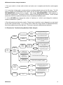
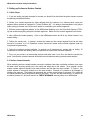
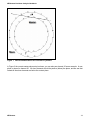
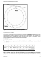
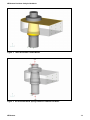
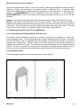
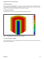
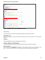
NEiNastran
NEiNastran Nonlinear Analysis Handbook
Version 9.0
NEiNastran Nonlinear Analysis Handbook
Information in this document is subject to change without notice and does not represent a commitment on the part of Noran Engineering, Inc.
The software described in this document is furnished under a license agreement or nondisclosure agreement. The software may be used or
copied only in accordance with the terms of the agreement. It is against the law to copy the software on any medium except as specifically
allowed in the license or nondisclosure agreement. No part of this manual may be reproduced or transmitted in any form or by any means,
electronic or mechanical, including photocopying and recording, for any purpose without the express written permission of Noran Engineering,
Inc. The material presented in this text is for illustrative and educational purposes only, and is not intended to be exhaustive or to apply to any
particular engineering problem or design. Noran Engineering, Inc. assumes no liability or responsibility to any person or company for direct or
indirect damages resulting from the use of any information contained herein.
Copyright © Noran Engineering, Inc. 2006. All rights reserved.
Printed and bound in the United States of America.
Noran Engineering, Inc.
5555 Garden Grove Blvd. Suite 300
Westminster, CA 92683-1886
U.S.A.
Tel:
Fax:
(714) 899-1220
(714) 899-1369
E-mail: [email protected]
URL: www.NENastran.com
NE, NE/, NEi and the NEi logo are registered trademarks Noran Engineering, Inc. NASTRAN is a registered trademark of the National
Aeronautics and Space Administration.
TABLE OF CONTENTS
NEiNastran Nonlinear Analysis Handbook
1. Introduction.............................................................................................................................4
2. Nonlinear Static Analysis.......................................................................................................5
2.1 General Guidelines......................................................................................................................... 5
2.2 Troubleshooting ............................................................................................................................. 5
2.3 Flowchart for Troubleshooting Nonlinear Static Analysis ......................................................... 6
3. Nonlinear Transient Analysis ................................................................................................7
3.1. Impact Analysis ............................................................................................................................. 7
3.1.1 Understanding of the Normal Modes of the Structure......................................................................7
3.1.2 Positioning of the Model ......................................................................................................................8
3.1.3 Multiple Subcases.................................................................................................................................8
4. Tips for Setting up Nonlinear Materials ................................................................................9
5. Setting up Surface-to-Surface Contact ...............................................................................10
5.1. Basic Steps .................................................................................................................................. 10
5.2. Surface Contact Normals ........................................................................................................... 10
5.3. BSCONP Settings........................................................................................................................ 12
5.4. Stabilizing Springs ...................................................................................................................... 13
5.5. Troubleshooting .......................................................................................................................... 15
5.6. Simulating Interference/Press Fit Using NEiNastran ............................................................... 16
5.6.1 Understanding of the Normal Modes of the Structure....................................................................16
5.6.2 Initial Strain Model ..............................................................................................................................16
5.6.3 Boundary Conditions .........................................................................................................................17
5.6.4 Mesh.....................................................................................................................................................17
5.6.5 Model Parameter .................................................................................................................................18
5.6.6 Analysis and Results..........................................................................................................................18
5.6.7 Interference/Press Fit Model..............................................................................................................18
5.6.8 Boundary Conditions .........................................................................................................................19
5.6.9 Data Manipulation in the Editor.........................................................................................................19
5.6.10 Results ...............................................................................................................................................21
6. Setting up Gap Contact Elements .......................................................................................22
7. Setting up Slide Line Contact Elements .............................................................................23
8. Using Enforced Displacements in Nonlinear Analysis......................................................24
8.1. Proper Method of Applying Enforced Displacements ............................................................. 24
8.2. Tricks for Linear and Nonlinear Analysis ................................................................................. 24
9. Performance..........................................................................................................................25
9.1. Contact Models............................................................................................................................ 25
NEiNastran Nonlinear Analysis Handbook
1. Introduction
There are many types of behavior that may be referred to as nonlinear. Some examples of nonlinear
behavior include materials that change properties as they are loaded, displacements which cause loads
to alter their distribution or magnitude, gaps which may open or close. The degree of nonlinearity may
be mild or severe.
In linear static analysis we assume that displacements and rotations are small, supports do not settle,
stress is directly proportional to strain, and loads maintain their original directions as the structure
deforms. Most problems can usually be considered linear because they are loaded in their linear elastic,
small deflection range. For these types of problems, the slight nonlinearity does not affect the results
and the difference between a linear and nonlinear solution is negligible.
While many practical problems can be solved using linear analysis, some or all of its inherent
assumptions may not be valid. Adjacent parts may make or break contact with the contact area
changing as the loads change. Elastic materials may become plastic, or the material may not have a
linear stress-strain relation at any stress level. Part of the structure may lose stiffness because of
buckling or material failure. Displacements and rotations may become large enough that equilibrium
equations must be written for the deformed rather than the original configuration. Large rotations cause
pressure loads to change in direction, and also to change in magnitude if there is a change in area to
which they are applied.
Unlike other solutions, subcase loads and results are additive. This allows different loads and boundary
conditions to be applied in a specific sequence to the structure. Additionally, different nonlinear iteration
parameters (NLPARM) may be specified for each subcase allowing further control. To initialize each
subcase to zero set PARAM, NLSUBCREINIT to ON; this setting allows multiple subcases, each having
the same zero starting point.
NEiNastran
4
NEiNastran Nonlinear Analysis Handbook
2. Nonlinear Static Analysis
2.1 General Guidelines
The following guidelines should be followed when building a nonlinear finite element analysis model:
1. Run the analysis as a linear static solution first and make sure the results are as expected.
2. Keep the model size small. Simplify the geometry as much as possible before meshing (unnecessary
fillets, holes, etc. should be removed). Identify areas of symmetry and cut the model at these planes and
apply symmetry boundary conditions. Using symmetry will not only reduce the model size considerably,
but the symmetry constraints will help to stabilize the model from rigid body movement.
3. Ensure a good quality mesh. The convergence of a nonlinear analysis can be affected by poor quality
elements. If the geometry is simple consider using a mapped plate mesh, or hex mesh for solid
elements. Perform distortion checks to make sure there are no severely distorted elements.
4. Only apply nonlinear materials in the areas of the model where you expect nonlinear or plastic
behavior. This will help to speed up the analysis and can improve the convergence rate.
5. If surface contact is being used, split up the contact areas into specific regions where you expect
contact to occur. Using broad or general surfaces will cause a large number of contact elements to be
generated, resulting in an increase in the analysis time.
2.2 Troubleshooting
The following steps should be used to diagnose problems when running any nonlinear static analysis:
1. Run your model in a linear static solution. Check that the run completed normally and that the results
appear correct. Also, check that the Epsilon value is small (< 1.0E-7) and review any warning
messages.
2. Setup a nonlinear analysis with large displacement effects turned off (uncheck the Large
Displacements box in the NEiNastran Modeler analysis window, or change LGDISP=OFF in the
NEiNastran Editor). If PARAM, LGDISP, 1 or ON appears in the Model Input File, change this to OFF.
3. Turn off any nonlinear materials (either in the NEiNastran Modeler or in the NEiNastran Editor by
commenting out the MATS1 card).
4. If the model still does not run after performing steps 2 and 3, go to the nonlinear analysis settings, set
the Number of Increments to 1, Output Control to YES, and Maximum Bisections (under the Advanced
button) to 1. You should then get 1 output set of results that you can examine to help diagnose the
problem in your model.
5. If you are able to get the model running as detailed in step 2, turn ON large displacement effects and
see if the model still converges. If it does, turn ON the nonlinear material and see if the model
converges.
6. If, after turning on the nonlinear material your model no longer converges, see Section 4 “Tips for
Setting up Nonlinear Materials” for additional info.
If you are getting an E5001: NON-POSITIVE DEFINITE DETECTED AT GRID id COMPONENT n, we
recommend you follow the steps listed below to diagnose what is causing the problem:
NEiNastran
5
NEiNastran Nonlinear Analysis Handbook
1. Run your model in a linear static solution and make sure it completes and that the results appear
correct.
2. If it runs okay in linear static, run the model as a nonlinear analysis and use the VIS solver. The VIS
solver is chosen in the NEiNastran Editor options (on the left side) under Program Control Directives –
DECOMPMETHOD (double click to change). Also change MAXSPARSEITER to 500 iterations to
shorten the analysis time. The goal is to force a solution to help diagnose the problem. Unlike all other
solvers the VIS will not produce a fatal error for an ill-conditioned stiffness matrix.
3. On the NLPARM card, change the number of iterations to 1 (field 3) and change the maximum
number of iterations to 1 (field 7).
4. Run this analysis and look at the results. Please keep in mind this is only a diagnostic run and should
not be used as actual results. If you see an area or node with a large amount of displacement/stress,
this is the probable cause of the fatal error. This may be caused by badly distorted elements.
2.3 Flowchart for Troubleshooting Nonlinear Static Analysis
YES
Use weak springs to stabilize the model.
See section 5.4 for more details.
NO
Look for unconnected elements and/or a
lack of constraints in the model.
YES
Check for negative slope on stress-strain
curve (slope should always stay positive).
Increase the number of increments. Check
for buckling of the model. See section 4 for
more details.
Surface Contact in
Model?
E5001Singularity
Nonlinear
Materials in
Model?
WARNING:
E5078:
Solution Has
Diverged
Nonlinear
Static
Analysis
Fatal Error
E5076:
Maximum
Number of
Bisections
Permitted
Reached
S1110
Insufficient
Memory error
Occurs
WARNING: E5080:
Excessive Grid Point
Incremental Rotations
NEiNastran
Decrease the contact stiffness scale
factor (SFACT on BSCONP card).
Try 0.1 or 0.01
NO
Structure may be buckling or
undergoing instability. Use weak
springs to stabilize the model. See
section 5.4 for more details.
Surface
Contact in
Model?
Structure may be buckling or is
unstable. Use Arc-Length to solve for
post-buckling type models.
WARNING: E5074: No
Convergence in
Maximum Number of
Iterations Permitted
Increase the maximum number of iterations
WARNIN: E5079:
Excessive Element
Internal Loads Detected
Increase the number of increments and/or increase the
Stress Fraction Limit (FSTRESS on NLPARM)
NO
Surface Contact in
Model?
YES
Analysis is
running slow
YES
Surface Contact in
Model?
NO
Consider reducing the size of the model.
Lower the RAM value (try 500). Implement
the /3GB switch for Windows XP. See
Appendix for more info.
If little sliding is expected, set
SLINEMAXACTDIST=AUTO. If error
persists set MAXADJEDGE = 50
Try varying the solvers as
described in Section 9.
6
NEiNastran Nonlinear Analysis Handbook
3. Nonlinear Transient Analysis
If the effects of inertia, damping, and transient loading are significant, then a nonlinear transient analysis
should be used. Additionally, ‘quasi-static’ models that undergo buckling or other instable loading
conditions will often converge better in a nonlinear transient analysis due to the inertia effects keeping
the model stable.
An important element to having a stable NLT (nonlinear transient) solution is to provide damping in the
model. There are two types of damping that can be applied in NLT solutions. The first type is a global
damping value specified using a PARAM,G followed by a PARAM,W3 which defines the frequency at
which to apply the damping (see the NEiNastran User’s Manual, Section 5 for more detailed information
on damping). The second type is material based damping and is defined on each material card directly.
PARAM,W4 is needed to define the frequency at which to apply the material based damping. Note that
the units of W3 and W4 are radians per unit time. The increased flexibility of material based damping
(i.e., different damping values can be applied to different areas/materials of the model) makes it the
logical choice for NLT analysis.
A note of caution: when using damping in a NLT solution is that for models where the velocity/inertia is
the main driver of the analysis such as in an impact solution, damping can have a significant effect on the
acceleration/velocity/displacement of the model. This is because the solver cannot make a distinction
between rigid body motion/velocity, and flexible motion/velocity, so the damping is applied to any part of
the structure that has a velocity. For impact analysis it is recommended to use no damping or a small
‘stability’ damping value (i.e., 1.E-6).
3.1. Impact Analysis
There are a few guidelines to follow when performing an impact analysis that will have a large impact on
solution time and quality of the results.
3.1.1 Understanding of the Normal Modes of the Structure
This is a very important and often overlooked stage. We need to know the linear response
characteristics of the structure to get some idea of what the actual nonlinear frequencies and mode
shapes are going to be. It can never be an exact representation, but it gets us in the right ball park for
several key input parameters.
•
•
•
Frequency range of interest
Size of time step
Duration of analysis
Constrain (fully fixed) the area of the model that you expect to make contact with the ground (or other
impactor) and run a normal modes solution with ~20 modes. Look at the mode shapes and find the
mode you would consider to be the ‘dominate’ response of the structure during/after impact. A look at
the modal effective mass table in the *.OUT file may also help determine the critical mode. The
frequency of the mode can be used to calculate the key input parameters above:
•
Frequency range of interest – This would be the frequency of the dominant mode.
•
Size of time step – This can be calculated using 1/f, and then assuming 100 data points per cycle
would net: dt = 1/ (100*f)
•
Duration of analysis – This largely depends upon the velocity of the impact, the size of the model,
and the flexibility of the model. A good estimate is to run the analysis for 2-5 cycles.
NEiNastran
7
NEiNastran Nonlinear Analysis Handbook
3.1.2 Positioning of the Model
In most situations it is best to perform a hand calculation to find the velocity at impact and then start the
two models near each other. This approach will net shorter analysis times, and better fidelity than
starting the two bodies at a physical distance (i.e., as in a drop test). A good method for calculating the
small separation distance is to use the equation, d = v * (2*dt), where d = separation distance, v =
velocity, and dt = time increment. This separation distance will allow for the solution of 2 time steps
before impact.
3.1.3 Multiple Subcases
When pre/post-impact behavior is desired, using multiple subcases is a good way to fine-tune the
analysis such that detailed time stepping can be used during impact, and a much coarser time-step can
be used after impact. This strategy is used and explained in the NEiNastran Tutorial Problem #8.
NEiNastran
8
NEiNastran Nonlinear Analysis Handbook
4. Tips for Setting up Nonlinear Materials
1. When performing an analysis that will have large amounts of strain it is recommended to use a
nonlinear elastic material.
2. Check that the slope of your stress strain curve (in the linear region) matches the Young’s Modulus of
the material.
3. If the slope of the stress strain curve is very “flat” (or negative) you may get a non-positive definite
error during the analysis. If acceptable, remove the flat area on the stress-strain curve and re-run the
analysis. If you must use a flat or negative slope stress-strain curve you can try and force a solution by
turning SOLUTIONERROR=ON and FACTDIAG=0. Also, try setting NLMATSFACT to 0.1 – 0.5.
4. When using a nonlinear plastic material, we suggest using a stress-strain curve instead of the BiLinear method. The Bi-Linear method essentially creates a stress strain curve with two different slopes.
This abrupt change in the elastic modulus makes it hard to converge on a solution.
NEiNastran
9
NEiNastran Nonlinear Analysis Handbook
5. Setting up Surface-to-Surface Contact
5.1. Basic Steps
1. If you are setting up plate elements for contact you should first check that the plate element normals
are pointing towards each other.
2. Define your contact segments by either defining them by surfaces or by element faces (using the
adjacent faces method as explained in Tutorial Problem #8). It is always recommended to use groups
when setting up contact, as it will be much easier to view/select your contact segments.
3. With the contact segments defined, (in the NEiNastran Modeler) go to the View-Quick Options (CTRLQ) and uncheck everything except the contact segments. Make sure the contact segments look correct.
4. Next, define the contact property. Click on the NEiNastran button and fill in any friction values if you
expect sliding.
5. Define the contact pair. In general, choose the master as the contact segment that has the least
amount of curvature, or if it is cylindrical contact choose the master as the outside segment (and use
unsymmetrical penetration).
6. Setup the nonlinear analysis settings. In general use 5 increments for contact with no sliding, 10
increments for contact with sliding, and 20 increments for contact with nonlinear materials.
7. First, run your model in a static/modal analysis and make sure it runs fine, and that the results look
good. Note that the contact elements will behave as weld elements during a static/modal analysis.
5.2. Surface Contact Normals
When modeling surface contact between concentric cylinders (and other undulating surfaces), care must
be taken when choosing which part is the slave and which part is the master. As a general rule the
master contact segment should be the outer surface, and the slave the inner surface. In Figure 1, the
master surface is incorrectly chosen to be the inner surface. Element 16 is shown as an example of
checking the normals. The dotted line represents the surface contact plane for element 16, in which all
the slave elements should be positive (above) this plane. You can see that elements 21-33 and 39-40
are below element 16, which will result in a ‘CHECK NORMALS’ warning when run in NEiNastran.
NEiNastran
10
NEiNastran Nonlinear Analysis Handbook
Figure 1. Incorrect Master-Slave for Concentric Cylinders
In Figure 2 the correct master-slave setup is shown; you can also see element 36 as an example. A new
plane is drawn for element 36. All slave elements should be positive (below) the plane, and we see that
indeed all the slave elements are below the contact plane.
NEiNastran
11
NEiNastran Nonlinear Analysis Handbook
Figure 2. Correct Master-Slave for Concentric Cylinders
A quick workaround would be:
If little sliding between the two parts is expected, the parameter, SLINEMAXACTDIST (located under
Nonlinear Solution Processor Parameters in the Editor) can be set to AUTO. With this setting only
nearby elements will be considered for contact, which will not only speed up the solution, but will
eliminate the problem of surface normals as in the above example.
5.3. BSCONP Settings
The explanations below expand upon the full list of definitions in the NEiNastran Reference Manual
under BSCONP.
SFACT – Stiffness Scale Factor. By default NEiNastran will use the material stiffness of the master
entity. Sometimes this can be too stiff and cause convergence problems. Setting the SFACT to 0.1
(10%) or 0.01 (1%) will often help with convergence. Be careful though, lowering SFACT too much may
NEiNastran
12
NEiNastran Nonlinear Analysis Handbook
cause penetration with the model. Usually 5% penetration (of an element width) is acceptable for a
contact model.
FSTIF – Frictional Stiffness for Stick. Calculated internally by the solver, so it is recommended to leave
this entry blank. A method of choosing a value is to divide the expected frictional strength (MU *
expected normal force) by reasonable value of the relative displacement before slip occurs. A large
stiffness value may cause poor convergence, while too small a value may result in reduced accuracy.
An alternative method is to specify the value of relative displacement using SMAX.
MAXAD – Maximum Activation Distance. This is the distance for which elements will check to see if they
are in contact or not. For models with little or no sliding, setting this to length of sliding will drastically cut
down the number of contact elements generated. When no sliding is expected, the AUTO setting is
recommended. This will use the element size as the distance. The maximum activation distance can be
set for each contact pair here or globally by using the SLINEMAXACTDIST parameter.
W0 – Surface Contact Offset. Surface contact is defined using the nodes. So if you are modeling a 2D
plate, by default the contact will take place at the centerline. To account for the thickness, you can use
this offset.
TMAX – Allowable penetration. There are two methods for adaptive stiffness updates: proximity stiffness
based and displacement based. If TMAX > 0.0, the displacement based update method is selected.
When TMAX = 0.0 (default), the proximity stiffness based update method is selected.
The
recommended allowable penetration TMAX is between 1% and 10% of the element thickness for plates
or the equivalent thickness for other elements that are connected to the contact element.
5.4. Stabilizing Springs
Model stability is an important factor in getting a nonlinear static surface contact model running properly.
As a general rule, surface contact should never be used to satisfy a stability constraint. To put it another
way, the model must be stable even if the surface contact was taken out. Numerically there will
generally be a small gap between the contacting surfaces. This gap means (initially) there will be no
stiffness transferred between the parts. If one of the parts is unconstrained it will cause a singularity in
the solver on the first increment.
The easiest way to remedy this is to add weak springs to stabilize the model. Figures 3 and 4 below
show a typical surface contact model consisting of two parts. The gold colors in Figure 3 represent
surfaces for contact. The lug back surface is held fixed in all directions. The stud/nut part initially has no
constraints, since in the real-world friction and contact will keep it stable. To make this a stable model for
an FEA solution, 6 springs are added (3 springs would be sufficient, but 6 allow for more symmetric
stability). Each spring is a 1 degree of freedom spring with a small stiffness in the respective direction
(x,y,z). The other ends of the springs are held fixed in all directions. These springs allow the contact to
‘seat’ or activate during the initial iterations, and once the contact is activated, the weak springs will no
longer influence the results. A good estimation of the spring stiffness to use is:
Kspring = 0.001 * Kmodel
where Kmodel = Applied Force / Est. Peak Deflection
NEiNastran
13
NEiNastran Nonlinear Analysis Handbook
Figure 3. Two Part Surface Contact Model
Figure 4. Six Grounded Weak Springs Added to Stabilize the Model
NEiNastran
14
NEiNastran Nonlinear Analysis Handbook
5.5. Troubleshooting
There are many reasons a contact analysis may not run to completion. The following are some tips at
getting the analysis to complete:
Problem: Your analysis is going very slow.
Solution: If you expect no sliding in the contact, set the parameter SLINEMAXACTDIST=AUTO. If you
expect some sliding set the parameter to a value slightly larger than the maximum amount of sliding you
would expect.
Problem: You are getting an E5072: WARNING: CHECK NORMAL FOR CONTACT ELEMENT id
CONTACT SEGMENT id warning message during the analysis.
Solution: See Section 5.2 for additional information. This warning means your normals for the contact
segments are pointing the wrong way. If they are shell elements, check the normal direction and reverse
if necessary. If they are solid elements, and you defined the contact via surfaces, consider trying to
define the contact via elements instead.
Problem: Your solution bisects until you reach maximum bisections and receive a fatal error of max
bisections reached.
Solution 1: This is the most common problem in contact analysis. The NEiNastran solver is having a
hard time converging during the analysis. The best trick in getting this to converge is to set SFACT = 0.1
or 0.01. This will reduce the stiffness of the contact and make it easier for NEiNastran to converge.
Note: Reducing SFACT will result in more penetration between contact surfaces, so after the analysis
completes be sure to check the amount of penetration to see if it is reasonable.
Solution 2: If your model has little (less than one element length) or no sliding, set the TMAX value on
the BSCONP to an accepted value of penetration (in your modeling units) that you are willing to accept.
A recommended value is 1-5% of the associated thickness of the parts in contact. Note that the larger
the value you choose, the easier it will be for the NEiNastran solver to converge, but the less accurate
the results may be.
Problem: You tried the above steps but your model still does not converge.
Solution 1: If your contact segment mesh is very coarse, consider re-meshing the area with a finer
mesh.
Solution 2: Set the number of increments to a larger value (i.e., from 5 to 10).
Solution 3: If your model is almost converging, try reducing the work, load, or displacement tolerances.
Problem: You are modeling gears with contact or rotating geometry and the analysis is not working.
Solution: You may need to set SLINEMAXPENDIST to a value that is approximately the size of one of
your element lengths. This will tell NEiNastran to ignore any contact pairs that appear to be penetrating
at a distance larger than this value.
Problem: You get an out of memory error at the very beginning of the analysis.
Solution: If you have large contact segments with a lot of elements and you receive this error, set the
parameter MAXADJEDGE=50
Problem: You are getting non-positive definite or singularity errors, yet you know your model is setup
correctly.
Solution: See Section 5.4 on adding stabilizing springs. If only a checkout run is needed, a faster
method is to use the parameter NLKDIAGAFACT which specifies the stiffness to be added to diagonal
NEiNastran
15
NEiNastran Nonlinear Analysis Handbook
terms of the global stiffness matrix (in units of the model). Specifying a small positive value is useful in
stabilizing a solution and preventing a non-positive definite or singularity error. In nonlinear static
solutions the added stiffness is decreased at the completion of each increment so to reach the value
defined by NLKDIAGMINAFACT at the completion of the last increment.
If the parameter,
NLKDIAGMINAFACT is left at zero (default), the augmented stiffness will be set to zero on the last
increment.
Problem: Your stress results appear spotty with stress concentrations where there should not be any.
Solution: The reason for this problem is due to irregular meshes. When two pieces are initially in
contact certain nodes on the contact surface may be closer than other nodes solely due to the geometry
of the mesh. The nodes that are closer will therefore have larger stress than other regions. The best
way to get more even results is to increase the mesh density at the contact interface.
5.6. Simulating Interference/Press Fit Using NEiNastran
5.6.1 Understanding of the Normal Modes of the Structure
The following section describes a technique to simulate an interference fit problem on a simple two
cylinder assembly model. The initial strain approach is used to compress the inner cylinder. The strains
from the initial strain model are reapplied to the inner cylinder of the interference fit model. The strain is
resolved to the original state. Surface contact in the model opposes the initial strain resolution thus
achieving the interference fit result. This technique has unique advantages over the thermal shrinking
method. The user can specify the exact amount of shrinking in the radial direction without having to
worry about a trial and error process to determine the right thermal load for the desired interference.
5.6.2 Initial Strain Model
The following figure shows the initial strain model set up (Units: English):
Figure 5. The Inner Cylinder in the Part Model with Boundary Conditions
NEiNastran
16
NEiNastran Nonlinear Analysis Handbook
5.6.3 Boundary Conditions
Figure 5 shows the inner cylinder model. The bottom and top surfaces of the cylinder are constrained in
the axial direction (z or 3 direction of the radial coordinate system seen in the bottom right areas of the
figure). The symmetry faces are constrained in the theta direction (y or 2 direction of the radial
coordinate system).
The enforced displacement load equal to the amount of interference desired is applied inward in the
radial direction on the outer surface of the cylinder. The definition and output coordinate systems of all
the grids of the model are changed to the radial coordinate system for convenience. Linear static
analysis is performed.
5.6.4 Mesh
The final meshed model with aluminum material and solid property with linear hex elements is shown
below:
Figure 6. The Inner Cylinder Mesh
Inner cylinder dimensions:
Inner radius: 2.5”
Outer Radius: 6”
Aluminum (common material):
E = 10700KSI
ν = 0.33
NEiNastran
17
NEiNastran Nonlinear Analysis Handbook
5.6.5 Model Parameter
Set the parameter TRSLSTRNDATA to ON under the Output Control Directives in NEiNastran Editor.
This parameter instructs NEiNastran to generate a ‘bdf’ file of the strain data from the initial strain
analysis. The strain data is later included in the interference fit analysis.
5.6.6 Analysis and Results
Radial displacement results of the initial strain model are presented in Figure 7.
Figure 7. Radial Displacement Plot of the Inner Cylinder
5.6.7 Interference/Press Fit Model
Figure 8 shows the set up of the assembly model with surface contact, linear hex elements with the
same material and properties.
NEiNastran
18
NEiNastran Nonlinear Analysis Handbook
Figure 8. Assembly Model with Surface Contact
5.6.8 Boundary Conditions
Figure 8 shows the model set up. The same mesh is used for the inner cylinder; this is important as the
strain data has to be applied to the same nodes for the analysis to run properly. The outer cylinder is
added to the model and meshed separately using hex elements. The symmetry faces are constrained in
theta in a similar fashion using the radial coordinate system. The bottom faces (not seen in the figure)
are constrained along the axial direction similar to the initial strain model. Surface contact is generated
between the contacting surfaces (orange color in the figure).
A nonlinear static analysis is set up and the model is written out with a new name to be opened in the
Editor.
5.6.9 Data Manipulation in the Editor
The following figure shows the bulk data in the Nastran tab inside the NEiNastran Editor. The red boxes
show the changes.
NEiNastran
19
NEiNastran Nonlinear Analysis Handbook
Figure 9. NEiNastran Editor with the NEiNastran Input File
Case Control:
The following Case Control command should be included in the interference fit model:
INITSTRAIN = 100
This instructs Nastran to look for Set 100 for initial strain values in the bdf file from the initial strain
analysis.
Bulk Data:
The following Bulk Data entry should be added to the input file:
INCLUDE, ‘PRESS FIT INITISTRAIN.BDF’
This instructs Nastran to include the strain data in the bdf file from the initial strain analysis.
Model Parameters:
Set the parameter, SLINEMAXDIST to AUTO under the Nonlinear Solution Control Parameters in the
Editor. This minimizes the number of unnecessary contact elements generated during analysis.
NEiNastran
20
NEiNastran Nonlinear Analysis Handbook
5.6.10 Results
After the analysis is finished, the initial radial compression of the inner part is resolved back to the
original state. The surface contact in the fit model opposes the resolution and thus the outer cylinder’s
inner surface is also pushed out radially as shown in the following figure.
Figure 10. Radial Displacement Plot of the Assembly Model
The inner cylinder’s material tends to flower out over the top edge of the outer cylinder which is the
expected flow of the material. The stresses in this region tend to be higher due to stress concentration.
NEiNastran
21
NEiNastran Nonlinear Analysis Handbook
6. Setting up Gap Contact Elements
The settings for the Initial Gap (-1) instruct NEiNastran to begin the analysis with the various physical
spacing between the nodes that are specified in the model geometry. The value for the Compression
Stiffness should be greater than the stiffness of the neighboring solid elements. The units are the same
as the Young’s Modulus entry. The optimal stiffness is determined iteratively. If the value is too stiff, the
solution time may be excessive and decreasing the value too much may cause inaccurate results. With
the Adaptive setting, the Max Penetration is a length parameter that allows NEiNastran to adapt the
gap properties for convergence. Its value should be much smaller than the solid element dimensions
around it. The best value is determined iteratively, when the solver converges quickly to a good result.
Small, non-zero values are chosen for the gap’s tension and transverse stiffness (weak springs).
NEiNastran
22
NEiNastran Nonlinear Analysis Handbook
7. Setting up Slide Line Contact Elements
NEiNastran adaptively adjusts the slide line stiffness. Entering the default value of zero in the Stiffness
Scale Factor field allows NEiNastran to determine the initial stiffness on its own. The Width values are
used to calculate the stress. The Symmetrical Penetration button determines how NEiNastran checks
for penetration and is the most accurate setting that will result in the least amount of penetration.
Tip: For models that contain a large amount of slide line contact elements that will not undertake any
sliding, we recommend setting the parameter SLINEMAXACTDIST=AUTO. This will result in a much
faster solution time.
NEiNastran
23
NEiNastran Nonlinear Analysis Handbook
8. Using Enforced Displacements in Nonlinear Analysis
Enforced displacements and rotations in NEiNastran are referenced by an SPCD Bulk Data entry. Some
confusion can arise when using enforced displacements because in most pre/post processors they are
created as a “load”, when in fact they are treated as a special type of constraint in NEiNastran. In
addition, an SPCD entry is referenced by a LOAD card in the Case Control.
8.1. Proper Method of Applying Enforced Displacements
For either linear or nonlinear static analysis, the following method will work correctly and not cause any
errors in NEiNastran:
1. Apply the enforced displacement in the appropriate direction.
2. Constrain the same nodes/surfaces/curves in the direction of the enforced displacement. It is
important that only the nodes that have the enforced displacement are constrained in the
direction of the displacement. All other constraints will be treated as actual boundary conditions.
8.2. Tricks for Linear and Nonlinear Analysis
For ease of use, NEiNastran will automatically create a constraint for the SPCD entry in certain situations
listed below:
1. Linear Static Analysis – A constraint will automatically be created for an SPCD entry for each
subcase, however, if the model has varying constraint sets it is recommended to use the method
listed in 2.
2. Nonlinear Analysis – If you use the same load set ID as the SPC ID then you do not need to
constrain the enforced displacement. For example:
SUBCASE 1
SPC = 1
LOAD = 1 (WHICH REFERS TO AN SPCD OR FORCE)
SUBCASE 2
SPC = 2
LOAD = 2 (WHICH REFERS TO AN SPCD OR FORCE)
Would work as is. No additional constraints would be required. However, the following:
SUBCASE 1
SPC = 1
LOAD = 1 (WHICH REFERS TO AN SPCD OR FORCE)
SUBCASE 2
SPC = 1
LOAD = 2 (WHICH REFERS TO AN SPCD OR FORCE)
Would require that in SPC set 1 the DOF that the SPCD refers to be constrained.
NEiNastran
24
NEiNastran Nonlinear Analysis Handbook
9. Performance
Nonlinear analysis will generally take at least an order of magnitude longer to run than a linear analysis.
Because of this fact, models should be simple and relatively small initially to gain insight into behavior
and verify the approach taken. A linear static solution should be run first to verify boundary conditions
and loading.
For nonlinear static solutions, several solvers are available, each with their own strengths. The list below
describes the advantages of each:
1. VSS – The VSS solver is a fast solver when the entire model will fit into memory. For a typical
desktop system with 1 GB of RAM, model sizes up to 100,000 DOF will run fastest using this
solver.
2. PCGLSS Direct – This solver is best when running large models, and/or when there is not a lot of
physical memory on the system. The PCGLSS Direct solver will generally use less memory than
the VSS solver.
3. PCGLSS Iterative – This solver uses the least amount of memory and is best for very large
models. Since this solver uses an iterative approach, element quality will directly effect how
many iterations are needed. The PCGLSS Iterative solver is often faster than the PCGLSS Direct
for good quality meshes.
4. VIS Solver – Unlike all other solvers the VIS will not produce a fatal error for an ill-conditioned
stiffness matrix. It is best used for performing checkout runs when problems exist with the model.
The VIS solver is an iterative solver and is generally slower that the PCGLSS Iterative solver.
To change the solver set DECOMPMETHOD=VSS/PCGLSS/VIS (located under Program Control
Directives on the left side of the Editor). The default setting is AUTO and allows the program to pick the
best method based on the RAM directive setting, material properties, model size, and solution selected in
the model. To switch between PCGLSS Direct and Iterative set the Parameter
SPARSEITERMETHOD=ITERATIVE or DIRECT (located under Solution Processor Parameters).
9.1. Contact Models
By default NEiNastran will generate a contact element for every combination between the master contact
elements and slave contact elements. For instance if a model contained a master contact segment with
2000 elements in it, and a slave segment with 500 elements in it, the total number of contact elements
generated would be 1,000,000 (2000*500). This many generated contact elements requires a large
amount of memory, and can often lead to a S1110 Insufficient Memory error. The parameter,
SLINEMAXACTDIST (located under Nonlinear Solution Processor Parameters) sets the distance (in the
units of the model) that the solver will look for and generate contact elements. The AUTO setting will use
a distance that is approximately 1 element width away. If we consider that for every master contact
element there will be 9 slave elements within 1 element width, the amount of contact elements generated
will only be 18,000 (2000*9) which is a reduction of 55x.
NEiNastran
25