1
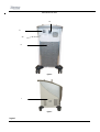
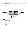
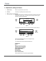
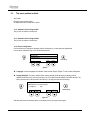
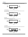
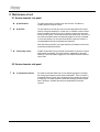
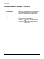
Zimmer Medizinsysteme GmbH
Junkersstrasse 9
Tel. +49 (0)731 / 9761-0
Fax +49 (0)731 / 9761-118
Manual
CryoMini
[email protected]
www.zimmer.de
Read Prior to Handling, Transporting or Operating CryoMini
CAUTION !
• Before handling, transporting or operating CryoMini, check the defrosted water
container to make sure that it is empty.
Once the container is empty, CryoMini can be turned onto its side (i.e. for transporting
or for changing the castors on the base), without resulting water damage.
• After transporting CryoMini (especially when turned onto its side):
- Wait at least 30 minutes before switching on the unit.
- Check the defrosted water container for correct placement
(at the side of the CryoMini).
• Installation of the CryoMini
- Do not place the CryoMini near a heating device:
heating system, fango unit, sauna, etc...
- Insure a minimum of 50 cm free space behind CryoMini for
air circulation.
Explanation of Symbols
In this manual this symbol indicates danger to patient, user or third person.
!
In this manual this symbol warns against possible harm to the unit.
Device type B: Protection level against electric shock.
CryoMini
These instructions form a part of the apparatus and must be kept with it at all times. Full observation of
these instructions is a requirement for the correct application and operation of the equipment and for
the consequent safety of both patient and operator.
! Note:
Following maintenance work or after being transported on its side, CryoMini must be left in the upright
position for a minimum of 30 minutes before being switched on to avoid damage to the compressor.
1.
2.
3.
4.
Content
Cryo in brief........................................................................................................................................................................ 5
Assembly instructions........................................................................................................................................................ 7
Operating instructions........................................................................................................................................................ 8
Adjustments, settings and menus..................................................................................................................................... 9
4.1.
The menu options in detail: .................................................................................................................................... 10
4.1.1.
Info.................................................................................................................................................................. 10
4.1.2.
Automatic Service Program S01 .................................................................................................................. 10
4.1.3.
Automatic Service Program S02 .................................................................................................................. 10
4.1.4.
Device Configuration ..................................................................................................................................... 10
4.1.5.
Default Settings: ............................................................................................................................................ 11
4.1.6.
Service: .......................................................................................................................................................... 11
4.1.7.
Defrosting:...................................................................................................................................................... 11
4.1.8.
Back to Treatment: ........................................................................................................................................ 12
5. Start of treatment ............................................................................................................................................................. 13
6. End of treatment .............................................................................................................................................................. 13
7. Time setting...................................................................................................................................................................... 13
8. Maintenance of unit ......................................................................................................................................................... 14
8.1.
Service elements: rear panel ................................................................................................................................. 14
8.2.
Service elements: side panel ................................................................................................................................. 14
9. Models, parameters and adjustments to preset values................................................................................................. 15
10.
Indications / Contra-indications for use in conjunction with laser treatment............................................................ 16
10.1. Indications ............................................................................................................................................................... 16
10.2. Contra-Indications................................................................................................................................................... 16
10.3. Treatment Information ............................................................................................................................................ 16
11.
Warnings...................................................................................................................................................................... 17
12.
Technical data ............................................................................................................................................................. 18
13.
Cleaning of exterior and disinfection of unit............................................................................................................... 19
14.
Advice on treatment and use...................................................................................................................................... 19
15.
UL Classification.......................................................................................................................................................... 20
16.
Parts included / accessories....................................................................................................................................... 21
17.
Safety and Maintenance ............................................................................................................................................. 21
17.1. Functional self- test ................................................................................................................................................ 21
18.
Fault signals ................................................................................................................................................................ 22
19.
Disposal ....................................................................................................................................................................... 22
1
Schematic Overview
Front side
4
3
5
2
1
figure 1
Legend:
1
2
3
4
5
6
Castor
Castor guards
Control Panel
Stand Off
Treatment hose nozzle connector
Treatment hose
2
Backside and left Side
10
9
20
8
figure 2
7
figure 3
Legend:
3
7
8
9
10
20
Condensate collector
Air filter
Main switch
Power inlet
Label
Control panel: controls and display
18.1
19.1
7
15
05:30
OK
Start/ Stop
19
18
figure 4
14
13
12
Key function:
11
12
13
14
15
16
17
18
18.1
19
19.1
16
Increasing of Therapy time
Decreasing of Therapy time
Increasing of fan speed level (figure 4)
Decreasing of fan speed level (figure 4)
OK
Start/Stop
Display of program number (figure 4)
Fan Symbol
Fan speed
Time Symbol
Therapy time
4
11
1. Cryo in brief
•
What is the CryoMini?
CryoMini may be used for skin cooling in conjunction with dermatological laser treatments to reduce pain and
thermal damage to skin tissue.
•
What does the CryoMini do?
The unit blows very low-temperature air, at adjustable fan settings, onto the desired treatment area.
•
What is the CryoMini's main advantage?
Its ease of use makes the CryoMini very simple to operate, while the level of performance it delivers in
continuous operation is normally found only in much larger devices.
•
What other advantages does the CryoMini have?
Cost-effectiveness. CryoMini cools through the medium of air, so is always ready for use without need for
supplies and incurs no running costs. The clear LCD display and ergonomically designed key pad represent the
latest technological developments.
•
How does CryoMini achieve the necessary concentration of cooling?
Air flow can be varied in 9 steps according to the size and accessibility of the area to be treated (level 1 = ~200
litres/min, level 9 = ~1300 litres/min).
Note:
The unit must only be operated by medical practitioners (e.g. doctors and nursing staff).
Caution: RX only = Federal law restricts this device to sale by or on the order of a physician!
5
•
The Minimal Load:
With "Load", we mean the time the device needs to produce a certain quantity of cold that will be stored as a
reserve. The "Minimal Load" of the CryoMini begins to be created as soon as the device is switched on. This
phase is characterized by the simultaneous working of the compressor and the Condenser fan. These 2
elements are always functioning together. During the Minimal Load, no functions are available and the display
indicates the status of loading (figure 7) no treatment is possible.
When the unit has reached its minimal cold temperature, you can start the therapy. The compressor and
Condenser fan still runs and now produce the Additional or Total Load;.
•
The Total Load (Additional:)
The Total Load refers to the steady maintenance of the maximum cold temperature in the cold reserve.
For example: During a treatment (Starting of the therapy fan with the Start Key), the compressor and the
condenser fan run automatically in order to compensate for the loss of cold capacity. When the therapy fan
stops (end of treatment) the compressor and condenser fan will continue running in order to complete the cold
reserve. During this loading period, treatment is possible. Afterwards, the unit remains in Stand-By Mode.
•
The Stand-by:
If the device is not used for approximately 30 minutes (in Stand-by Mode), the cold reserve will naturally loose
part of its capacity. The compressor and condenser fan will then start running in order to complete the cold
reserve. During the Stand-by Mode, treatment is possible.
Cold reserve additions are made automatically. The frequency required to maintain an adequate cold reserve
will vary according to the surrounding climatic conditions.
•
Important Advice for Optimal Use:
The first treatment should be made after the cold reserve is complete or Total Load and not after the Minimal
Load. Otherwise, the possibility exists that the unit may not have enough cold reserve for subsequent
treatments; it would then automatically proceed to the Minimal Load and treatment would not be possible for a
few minutes.
6
2. Assembly instructions
•
Step 1: Treatment tube (6)
Attach the treatment tube to the air outlet of the CryoMini (5, figure 1).
figure 5
•
Step2: Angle adaptor
Attach the accessory storage box through the felt on the top of the unit. (If included)
7
3. Operating instructions
1. Switch unit on
Power on (9), the treatment display is illuminated.
2. Operating status/ and Therapy
While start up the display indicates the current status (e.g. self-test, pre-treatment
cooling). The unit is ready for use once the treatment display is lit.
After the pre-cooling phase the device releases the therapy screen.
You now can directly select the desired fan speed and therapy time. Pressing the
Start/Stop button starts the therapy.
7
05:30
OK
Start/ Stop
figure 6
3. End of treatment
The end of the program, whether automatically (the cold air supply is cut off) or by
the operator having pressed the Start/Stop button, is indicated with an acoustic
signal.
8
4. Adjustments, settings and menus
1. Switch unit on:
Switch on at power switch (9, rear of unit).
2. Self-test:
On switch-on, CryoMini performs a self-test routine.
3. Making changes to system menu:
During the self-test and the pre-treatment cooling period, the system menu may be
accessed and changes made - e.g. settings may be changed, a desired program
selected or a custom program defined.
Pre-cooling
0%
100%
OK
Menu
figure 7
To enter the menu selection mode, press the button beneath the menu field (11).
OK
Own Programs
Favorite
Info
Automatic Service Program S01
Automatic Service Program S02
Start/ Stop
Select
figure 8
Use the keys marked with arrows (13+14) to navigate through
the 11 menu items available.
The individual menu items are described in detail below:
Own programs
Favorite
Info
Automatic Service Program S01
Automatic Service Program S02
Device Configuration (same)
Default Settings (same)
Service (same)
Defrosting (same)
Back to Treatment (same)
Use the selection key (11) to choose the required submenu.
9
4.1.
The menu options in detail:
4.1.1. Info
Displays system technical data.
No adjustments can be made in this option.
4.1.2. Automatic Service Program S01
Only for use at request of a technician.
4.1.3. Automatic Service Program S02
Only for use at request of a technician.
4.1.4. Device Configuration
Use this submenu to change the language used in the displays or to make technical adjustments.
Use the arrow and Select keys to choose the desired option.
OK
Display-Contrast
Start sequence
Language
Display-Backlight
Display-Contrast
Start/ Stop
Back
Select
figure 9
è Language: Various languages are available; these include German, English, French, Italian and Spanish.
è Display-Backlight: The time to elapse before entering standby mode (dimming of display) may be
adjusted under this menu. Use the arrow keys (13+14) to select a period between 0 and 300 seconds. The
factory-preset value is 180 seconds. Press Store (11) to apply and save the new setting.
Delay time prior to screen saver
(Alternative: 0=> no screen saver)
[1..300] sec:
180
OK
Start/ Stop
Back
Store
figure 10
Standby mode saves unnecessary wear on the display and so prolongs its working life.
10
è Display-Contrast: Use the setting to adjust the brightness of the display between 10 (maximum contrast) to
23 (very low contrast).
Setting of Display-Contrast
Contrast Value (0-23) :
18
OK
Start/ Stop
Back
Store
figure 11
4.1.5. Default Settings:
Select either YES or NO (11+12). No other option is available. If YES is selected, all settings are returned to
their original default values.
Reset default configuration?
OK
Start/ Stop
Yes
No
figure 12
4.1.6. Service:
This option is password-protected and accessible only by
personnel trained by Zimmer MedizinSysteme. To leave this menu option, press OK (15).
Please enter passwort:
[............]
OK
Start/ Stop
1
2
3
4
figure 13
4.1.7. Defrosting:
Defrosting begins immediately the Defrost program is selected. It can be cancelled by pressing the Back key
(12). The evaporator is defrosted.
Defrost mode activated
0%
100%
Start/ Stop
OK
Back
figure 14
11
4.1.8. Back to Treatment:
This option exits the menu and returns to the treatment display.
12
5. Start of treatment
Therapy screen:
7
05:30
OK
Start/ Stop
figure 15
After pre-cooling the CryoMini is ready for treatment. Pressing the Start/Stop button starts treatment
6. End of treatment
When the program time has elapsed, the air supply is cut off and an acoustic signal is emitted. The program can also be
ended manually by pressing the Start/Stop key (16).
7. Time setting
Times between 00:00 and 99:59 minutes may be set.
Pressing the up or down key once increases or decreases the treatment time for 1 minute.
By holding the up or down key increases or decreases the treatment time in steps of 10 minutes.
If an excessively long time has been inadvertently set, pressing the Start/Stop key (16) twice will revert the system to the
factory preset time for the program, which in some cases will help speed up the process of adjusting the time downwards
to the correct value.
13
8. Maintenance of unit
8.1. Service elements: rear panel
!
è (9) On/off switch:
The main power switch is located to the rear of the unit. On switch-on,
CryoMini performs a self-test routine.
è (8) Air filter:
The unit features an air filter (8) to remove coarse dust particles from the air
used for cooling and treatment. In normal use, it is sufficient to clean the filter,
which is located to the rear of the unit, by drawing a vacuum cleaner nozzle
across its outer surface. This should be carried out at least every 150 hours of
use, when the software issues a corresponding signal. If the unit is operated
in rooms with carpets or in other environments with a high level of dust, it is
recommended that the filter be cleaned more frequently.
Note: After cleaning the filter, the signal issued by the software must be reset
by pressing the appropriate button.
!
è Power safety cutout:
CryoMini is fitted with a 2-pole overload circuit breaker to protect the unit from
power supply irregularities. The circuit breaker is integrated into the on/off
switch (9). If the circuit breaker triggers, the unit must be switched off before it
can be reset.
8.2. Service elements: side panel
!
è (7) Condensate collector:
If CryoMini is switched off after use or if the defrosting program is activated,
the cooling system warms up and creates condensation. The unit contains a
condensate collector vessel, which holds about 2 liters and may be removed
for emptying. The vessel should be cleaned after emptying and then placed
back in the device. CryoMini should not be operated with the collector
removed.
14
9. Models, parameters and adjustments to preset values
è Models:
Different models are available to suit different power supply voltages.
è Preset parameters:
Each unit leaves the manufacturer with a set of standard parameters
preset. These may be restored at any time by selecting the Main
Settings function (see Adjustments, Settings and Menus, above).
è Adjustments to preset parameters:
CryoMini allows the airflow and treatment time to be adapted to suit
specific requirements and for the new values to be saved in the unit’s
memory (see Adjustments, Settings and Menus).
1. Air flow rate:
The treatment fan can be adjusted through nine
levels.
2. Treatment time: Treatment time may be adjusted between 00:00
and 99:59 minutes.
15
10. Indications / Contra-indications for use in conjunction with laser
treatment
10.1. Indications
The CryoMini Cold Air Device is intended to minimize pain and thermal injury during laser and dermatological
treatments and for temporary topical anaesthetic relief for injections.
10.2. Contra-Indications
è
è
è
è
è
è
è
è
è
Hyper-sensitivity to cold
Areas of impaired sensation
Areas of impaired circulation
Open wounds
Ablative laser treatment
Frostbite
Raynaud disease
Cryo-globulinemia
Cold-agglutinin disease
10.3. Treatment Information
Prior to the therapy the patient has to be instructed about the effects of the use of the CryoMini skin cooling system.
If the patient is feeling increasing discomfort or a sensation of excessive heat or cold he has to inform the
appropriate clinical staff.
The airflow level and the distance between the treatment tube’s handpiece and the treated area should be selected
to maximize patient’s comfort. During the treatment the patient has to be asked about his sensations. If necessary
the treatment parameters (airflow and therapy distance) should be modified.
For temporary topical anesthetic relief for injections, the treated area should be cooled to a comfortable level for the
patient. Prior to the injection, the treated area must be disinfected to avoid contamination.
16
11.
!
Warnings
è The device may only be used by trained medical personal
!
è Following transport or storage on its side, the unit must be placed upright and left for at least 30 minutes
before being switched on. Failure to observe this may result in damage to the cooling system.
!
è Do not place the unit in direct contact with sources of heat (radiators, mud preparations, saunas etc).
Ensure a distance of at least 20 inches (50cm) between the unit and the wall to allow air inflow.
!
è Unfavorable ambient conditions (e.g. ambient temperature above 86°F (30°C) and high humidity) may lead
to a reduction in performance (reduced cooling capacity).
è Magnetic and electric fields may affect the operation of the unit. Do not use CryoMini close to equipment
that generates strong electromagnetic fields (e.g. X-ray or diathermy equipment or nuclear magnetic
resonance tomography devices)
è Dispose of packaging material properly. Keep such material out of reach of children.
è CryoMini is not designed for use in environments with an explosive or inflammable atmosphere.
è To avoid contamination with non-filtered air on open wounds, the CryoMini must not be used during or after
injection.
è To avoid freezer burns and over-cooling, the air stream should be directed evenly over the entire area to be
treated. Static cooling, or overly intensive cooling, should be avoided.
è Do not increase laser output power or energy when using CryoMini for skin cooling
è Skin cooling may reduce effectiveness of some laser treatment on identical power output of the laser.
17
12.
Technical data
Electrical rating:
Supply voltage
Current consumption:
Supply protection in unit:
Protection level:
Application class:
MedGV group:
MPG class:
General:
Temperature for storage/transport:
Pressure for storage/transport:
Ambient operating temperature:
Operation Pressure:
Internal specifications:
Low-voltage systems within unit:
Evaporator temperatures
120 V˜/50Hz/60Hz (SN 400300 - 401999)
standby:
~1A
maximum:
8-10A
16A circuit breaker in power on/off switch
I
Type B, in accordance with IEC 601-1
3
I
14°F – 150°F max (-10°C - 70°C max)
600-1200hPa
32°F – 86°F max (0°C - 35°C max)
700-1200hPa
12V
Protection: Multifuse 500mA
12V
Protection: Multifuse 50mA
minimum (standby):
-4°F (-20°C)
maximum (standby):
14°F (-10°C)
maximum (operating):
23°F (-5°C)
Treatment data:
Air temperature at nozzle (ambient temperature 77°F (25°C) or
less)
average:
14°F (- 10°C)
at start of treatment:
-4°F (- 20°C)
maximum:
23°F (- 5°C) (after 15 min. treatment)
Airflow rates:
Level 1:
Level 2:
Level 3:
Level 4:
Level 5:
Level 6:
Level 7:
Level 8:
Level 9:
Maximum treatment time setting:
99:59 minutes
Physical data:
Physical dimensions
External dimensions:
Castors with diameter
Weight: 35,5kg
650x335mmx600mm (HxWxL)
75mm
250 l/min
440 l/min
627 l/min
780 l/min
910 l/min
1050 l/min
1150 l/min
1250 l/min
1350 l/min
Maximum load to be placed on the table surface (glass plate):
Equipment (e.g. lasers) with a maximum weight of 65lbs (30kg) and
maximum dimensions 20x20x19inches (50x50x48cm) (WxDxH)
may be placed on any plate fixable on the Stand offs.
18
! 13. Cleaning of exterior and disinfection of unit
è Clean the exterior of CryoMini with commercial synthetic cleaner or furniture polish (but not alcohol-based).
è For the glass table surface and the treatment tube, alcohol or spirit is recommended.
è To disinfect the unit and its attachments, use commercial equipment disinfectant in accordance with its
manufacturer’s instructions.
è The condensate collector should be disinfected each time it is emptied using a commercial disinfectant.
14. Advice on treatment and use
è To treat larger areas, the distance from the nozzle to the skin should be increased, resulting in longer
treatment times for adequate cooling.
è At a distance of 5cm, the cooling spot covers app. 10cm2.
è Hygienic gloves should be worn during the treatment.
è Before treatment, the purpose and effect of cryotherapy using CryoMini should be explained to the patient.
è Advise the patient to report any adverse reactions during treatment (e.g. extreme cold sensations)
immediately to the practitioner.
è Throughout the treatment, the practitioner should check the wellbeing of the patient by asking appropriate
questions.
è If necessary, adjust the treatment parameters (air flow rate, distance from treatment area).
è For use in conjunction with laser equipment, a distance of 2 inches (5cm) is recommended for a treatment
area of 4 square inches (10cm²). Larger areas should be treated using a correspondingly larger distance. In
such cases, a longer treatment time is necessary to achieve the required cooling
19
15.
UL Classification
The device bears the following UL Mark:
CLASSIFIED BY UNDERWRITERS LABORATORIES INC.
WITH RESPECT TO ELECTRIC SHOCK, FIRE,
MECHANICAL HAZARDS ONLY
IN ACCORDANCE WITH UL 60601-1 AND CAN/CSA C22.2 NO. 601.1
1KD1
20
16.
Parts included / accessories
Only authorized accessories should be used.
Accessories delivered with unit:
1 User Manual
1 Lightweight tube for laser treatments
1 Container for defrosted water
Available Accessories:
Lightweight tube for laser treatments
Container for defrosted water
Castors ∅75 mm
Angel adaptor for laser therapy
Reduction nozzle 5mm
Reduction nozzle 10mm
Reduction nozzle 15mm
17.
Safety and Maintenance
CryoMini is manufactured in accordance to VDE 0750 part 1(DIN EN 60601-1) safety regulations.
As the manufacturer, Zimmer MedizinSysteme GmbH assumes responsibility for the safety and reliability of the unit only
on the following conditions:
è that the unit is supplied from an electrical socket with safety contact that meets all regulations and the electricity
supply conforms to DIN VDE 0100 part 710
è that the unit is operated in accordance with the instruction manual
è that any expansions, readjustments or modifications are carried out exclusively by personnel acting on behalf of
Zimmer MedizinSysteme GmbH.
The unit contains no user serviceable parts, with the exception of the air filter (8, chapter 8.1, page 17) and the
condensate collector (7, chapter 8.2, page 17).
17.1. Functional self- test
On switch-on, CryoMini performs an automatic self-test and checks the operation of its various components.
If necessary, the operation of the cooling system may also be checked as follows:
1. Switch the unit on.
2. Wait until unit reaches its ready state. This is indicated when the therapy menu appears (see Adjustments,
Settings and Menus).
3. Press the Start/Stop button (16) to start operation.
4. Select the various air flow levels and check the air flow rate and cooling achieved.
21
18.
Fault signals
Error and fault signals appear in text form on the display, in some cases a possible cause is indicated.
In some cases, the error is self-correctable after the device has been switched-off. In this case, wait a few seconds and
switch the device back on.
If the error indication is still displayed after switching the device back on, contact customer service.
In the event of Error “High temperature cooling circuit”, switch off the device and wait 30 minutes before switching on
again.
Certified Service Personnel can be reached by contacting the sales representative or by contacting Zimmer
MedizinSysteme directly.
When the expulsed air or air volume temperature is decreasing, defrosting is necessary.
19.
Disposal
The unit must be disposed of through an accredited company and should under no circumstances be placed in the
ordinary or bulk waste.
Manufacturer:
Zimmer
Medizinsysteme GmbH
Junkersstrasse 9
D- 89231 Neu-Ulm
Tel.: +49 (0)731 / 9761-291
Fax: +49 (0)731 / 9761-299
www.zimmer.de
[email protected]
Manufactured for :
Zimmer
MedizinSystems
25 Mauchly, Suite 300
Irvine, CA. 92618
800 327 3576
949 727 2154 fax
www.zimmerusa.com
[email protected]
22