1
ROBO Master
OPS 656
USER'S MANUAL
MANUAL NO. OPS656m-UM-155
Software Usage Agreement................................................................................. 2
Registered Trademarks........................................................................................ 2
Notes on this Manual........................................................................................... 2
Disclaimer............................................................................................................ 2
4.2
4.3
4.4
1 Introduction...............................................................................3
4.5
4.6
4.7
1.1
1.2
1.3
Features..................................................................................................... 3
System Requirements................................................................................ 3
Points to Note............................................................................................. 3
2 Installing ROBO Master............................................................4
2.1
2.2
Launching the Installer............................................................................... 4
Installing ROBO Master............................................................................. 5
Installation procedure............................................................................. 5
3 Basic Operations.......................................................................6
3.1
3.2
3.3
3.4
3.5
3.6
3.7
Launching and Exiting................................................................................ 6
Initial Steps................................................................................................ 7
Cutting Text Outlines.................................................................................. 7
Cutting a Text String Placed Inside an Ellipse (CC330-20 Only)............... 9
Cutting the Contour of a Printed Image (CC330-20 Only)....................... 12
How to Trace and Cut an Outline of an Image (CC330-20 Only)............. 14
For Easy Operation.................................................................................. 15
4 Function Details......................................................................16
4.1
Main Window............................................................................................ 16
4.1.1 File Menu................................................................................... 16
4.1.2 Edit Menu................................................................................... 16
4.1.3 View Menu.................................................................................. 17
4.1.4 Draw Menu................................................................................. 18
4.1.5 Insert Menu................................................................................ 21
4.1.6 Window Menu............................................................................. 21
4.1.7 Help Menu.................................................................................. 21
4.1.8 Craft ROBO Logo....................................................................... 21
4.8
4.9
4.10
4.11
4.12
4.13
4.14
4.15
4.16
4.17
4.18
Document Settings Window..................................................................... 22
Preferences Window................................................................................ 23
Preview Display........................................................................................ 23
4.4.1 Output Menu.............................................................................. 23
4.4.2 View Menu.................................................................................. 23
Output To Printer Window........................................................................ 24
Output to Craft ROBO Window................................................................ 24
Output Settings Window........................................................................... 25
4.7.1 Always Displayed Items............................................................. 25
4.7.2 Common Settings....................................................................... 25
4.7.3 Print Settings.............................................................................. 26
4.7.4 Cutting Settings.......................................................................... 26
Cutline Settings Window.......................................................................... 27
Auto Trace Window.................................................................................. 28
Offset Window.......................................................................................... 29
Registration Mark Settings Window (CC330-20 Only)..................................... 30
Grid Settings Window.............................................................................. 31
Line Settings Window............................................................................... 31
Fill Settings Window................................................................................. 32
Text Settings Window............................................................................... 33
Position Window....................................................................................... 34
Metafile Loading Settings Window........................................................... 34
Save to SD Card Window......................................................................... 35
4.18.1 When saving cutting data to an SD card for the first
time (when there is no "Graphtec" folder in the SD card)........ 35
4.18.2 When saving in an SD card that already has the "Graphtec"
folder ...................................................................................... 35
5 Printing the Register Mark Test Form (CC330-20 Only).......36
6 Error Messages.......................................................................37
Operation-related Errors...................................................................... 37
Twain Errors......................................................................................... 38
File Loading Errors............................................................................... 38
Index ................................................................................................................. 39
Contents
Index
ROBO Master
OPS656
Software Usage Agreement
Registered Trademarks
Graphtec Corporation ("Graphtec") hereby grants the purchaser and authorized User
(the "User") the right to use the software (the "Software") in accordance with the terms
and conditions specified. By its purchase and use of the Software, the User hereby
accepts and agrees to abide by the terms and conditions set forth herein.
(1) The company names and product names described in this manual are registered
trademarks of their respective owners.
(2) The "ROBO Master" software and this manual are copyrights of Graphtec
Corporation.
1.Copyrights
Notes on this Manual
All copyrights relating to the Software and accompanying printed materials such as
manuals shall be retained by the individuals or organizations indicated in the Software
or printed material.
(1) The contents of this manual may not be copied in part or in whole without
permission.
2.License
(2) The details and product specifications in this manual are subject to change
without notice.
The User may use the Software on one computer at a time.
(3) The greatest effort has been taken to ensure the clarity and accuracy of the
information in this manual. Please contact Graphtec or your retailer with any
questions you may have.
3.Copying and modification
(1) The User may copy the Software for backup purposes. In that case, the User should label the copy with the same copyright notices as
apply to the Software.
(4) Please note that Graphtec assumes no responsibility for any liabilities arising out
of the use of this manual and product.
(2) The User may not modify, combine, amend, or otherwise adapt the Software by
any means, including disassembly and decompiling.
Disclaimer
4.Third-party use
Some of the software images used in this manual are those that were used when the
software was under development, and they may be slightly different from those actually
displayed. There are no differences between the functions and setting layouts shown
here and those of the actual version. We ask for your understanding.
The User may not transfer, assign, or otherwise dispose of the rights relating to the
Software or its use to third parties.
5.Warranty
(1) Should the Software not operate correctly due to physical defects in the Software
storage medium, contact your retailer. The product will be exchanged free of
charge in the case of a physical manufacturing defect.
(2) Graphtec only guarantees the storage medium under the above situation.
(3) Graphtec provides the Software on an "as is" basis. Neither Graphtec nor the
supplier guarantees the performance or results that may be achieved using the
Software and accompanying documentation. Neither Graphtec nor the supplier
gives any explicit or implicit guarantees regarding the infringement of a third
party's rights arising from the use of the Software or accompanying manuals,
their commercial performance, or their suitability for specific purposes. Neither
Graphtec nor the supplier assumes any responsibility for incidental, secondary, or
special damages resulting from the use of the Software or accompanying manuals
under any circumstances, including cases in which the possibility of that particular
damage arising is indicated to the User by the retailer. Moreover, neither Graphtec
nor the supplier assumes any responsibility for claims from third parties.
Contents
Index
ROBO Master
OPS656
1 Introduction
1.3 Points to Note
•While importing DXF files only the following DXF objects can be loaded: Lines,
polylines, splines, circles, arcs, and ellipses. Block-referenced objects or splines,
text, and dimension lines cannot be loaded.
•For details on setting and operating the Craft ROBO, please refer to the Craft ROBO
user's manual.
The ROBO Master is editing/output software that enables the creation of outline data
consisting of simple objects and text, and the output of the created data to the Craft
ROBO Cutting plotter. Furthermore, it supports convenient functions that enable the
capturing of image data into the software and the automatic creation of registration
marks for Print & Cut applications.
*In this manual, screens that appear when CC330-20 is connected to Windows Vista are
used.
*Automatic creation of registration marks is available only for the CC330-20.
1.1 Features
The ROBO Master has the following features:
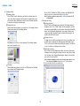
(1) Supports a function for automatically creating registration marks.
(2) Provides a preview display of a printed image, cut image, or combined image.
(3) Can load DXF files in AutoCAD R13 format.
(4) Allows Output/Do not output selection for each line color when outputting to the
Craft ROBO.
(5) To facilitate weeding of the cut media, the Weed Border function enables
automatic cutting of a border when outputting to the Craft ROBO.
(6) Any object exceeding the Craft ROBO's cutting range can be output in multiple
pages using the Tiling function when outputting to the Craft ROBO.
1.2 System Requirements
The following system environment (higher environment than one your OS
recommends) is required to use the ROBO Master.
•Operating System: Windows 2000/Windows XP/Windows Vista
(64bit OS is not supported.)
•CPU: Pentium III 800 MHz or higher
•Memory: 512 MB or more
•Monitor: 1024 x 768 True color
•Mouse
•CD-ROM drive
•Supported cutting plotter: Craft ROBO (CC300-20/CC330-20)
•Supported printers: Windows-compatible printers (inkjet printers recommended)
Note: When installing the software, be sure to log on using an account with Administrator
rights.
Contents
Index
ROBO Master
OPS656
2 Installing ROBO Master
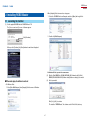
•When [Autoplay] Selection menu does not appear:
1. Select the CD-ROM Drive from Computer, and select [Open] with a right click.
2.1 Launching the Installer
(1) Set the supplied CD-ROM into the CD-ROM Drive of PC.
The [User account control] screen of software appears.
2. Double-click [MultiSetup.exe].
Click [Continue].
When you click [Continue], the [Start] window shown below is displayed.
*For Windows XP/2000, operate in the same manner.
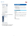
(2) Click the [Craft ROBO Lite (CC300-20/CC300L-20) Software Install] or [Craft
ROBO (CC330-20/CC330L-20) Software Install] button according to your model.
(3) Select your model.
n When auto play of software is not set
•For Windows Vista:
1. Select [Run MultiSetup.exe] from [Autoplay] Selection menu of Windows.
Click [Yes] or [No] to continue.
The installer of "ROBO Master," the software used for Print & Cut, starts up.
Contents
Index
ROBO Master
OPS656
2.2 Installing ROBO Master
(2) The "License Agreement" screen will be displayed.
Click "Install Craft ROBO Software" in the [Start] window to launch the ROBO Master
installer.
Note: •Be sure to close any open Windows applications before installing ROBO Master.
•If the Craft ROBO Controller has already been installed, select "Control Panel" →
"Programs and Features" ("Add or Remove Programs" for Windows XP, or "Add/
Remove Programs" for Windows 2000) and then uninstall the program before
performing the setup operation.
•When the ROBO Master installation operation has been completed, the Craft ROBO
Controller and the Craft ROBO driver are installed automatically.
Installation procedure
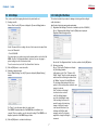
(1) When the installer is launched, the screen shown below is displayed first.
Carefully read the provisions of the agreement, and click [Yes] to continue the
installation.
(3) The "Choose Destination Location" screen will be displayed.
Click [Next] to proceed.
If you want to change the folder, click the [Browse] button and select a folder.
Click [Next] to proceed.
(4) The "Select Program Folder" screen will be displayed.
Program Folder is the name of a folder displayed in the Windows [Start] menu.
If you do not want to change the folder, simply click [Next] to proceed.
Contents
Index
ROBO Master
OPS656
3 Basic Operations
(5) The "Setup Type" screen will be displayed.
This chapter describes the basic ROBO Master operations, from launching the
software application to cutting.
Note: The term "media" as used in the body of this manual refers to paper, film, and other
materials to be cut or printed on.
3.1 Launching and Exiting
Launching
Double-click the shortcut icon of the ROBO Master on the Windows desktop to start up
the software.
Select "Place an icon on the desktop".
Click [Next] to proceed.
•If you have cleared the "Place an icon on the desktop" check box when installing the
software:
(6) When the system has finished copying files, an "Install Shield Wizard Complete"
screen is displayed.
Click [Start] → [(All) Programs] → [Craft ROBO] → [ROBO Master] to start up the
software.
Exiting
To exit, click "Exit" in the [File] menu.
Click [Finish] to complete the installation.
(7) When the installation of this program has been completed, the installer will then
proceed to install the Craft ROBO Controller and the Craft ROBO driver.
Contents
Index
ROBO Master
OPS656
3.2 Initial Steps
3.3 Cutting Text Outlines
First, create a new file for designing the artwork to be printed and/or cut.
This section describes the procedure for drawing a text string and then cutting its
outline (text border).
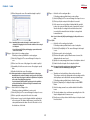
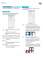
(1) Creating a new file Choose "New" from the [File] menu to display the [Document Settings] window.
Note: For the CC300-20, be sure to use the carrier sheet.
(1) Registration Mark Settings (This function is available only for the CC330-20.)
Choose "Registration Mark Settings" from the [Edit] menu to display the
[Registration Mark Settings] window.
Set the "Document Size" according to the size of the document to be output. Next,
choose the "Orientation".
•For the CC330-20:
If you are going to use a printer to print out the artwork and then cut it on the Craft
ROBO, select the "Use Registration Marks" check box. If you are only going to
perform cutting, leave the check box deselected.
To use the carrier sheet, select the "Use Carrier Sheet" check box.
(2) Click the [OK] button to create the new file.
(3) Setting the output destination Choose "Output Settings" from the [File] menu to display the [Output Settings]
window.
Deselect the "Use Registration Marks" check box, and then click the [OK] button.
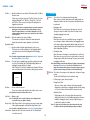
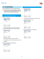
(2) Entering a text string
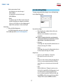
Choose "Text" from the [Draw] menu to display
the [Text Settings] window.
In this window, set the "Font", "Charactor Set",
"Width", "Height", "Angle", and other parameters,
and then enter the text string to be drawn. Select
the "Outline" check box. Click the [OK] button.
The text string will be displayed at the cursor
position. Left-click at the position at which the text
string is to be placed.
If the "Use Mouse to Set Angle"
check box has been selected
in the [Text Settings] window,
proceed to determining the angle
of the text string. As the mouse is
moved, the angle of the text string
changes. Left-click at the angle
to be entered. At this time, if you
hold down the [Shift] key while
moving the mouse, the text string
angle will be changed in 45-degree
increments.
For "Printer", select the printer driver to be used to print. "Craft ROBO" is displayed when the Craft ROBO driver is installed in your
computer. There is normally no need to change this setting. If "Craft ROBO" is not
displayed, perform the Craft ROBO setup procedure.
(4) Click the [OK] button to conclude the initial steps.
Contents
Index
ROBO Master
OPS656
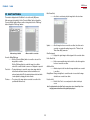
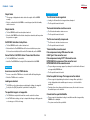
(3) Making the cut data settings Choose "Output Settings" from the [File] menu to display the [Output Settings]
window. Choose the [Cutting Settings] tab in this window, and click the [Cutline
Settings] button. The [Cutline Settings] window will be displayed. Confirm that
the color for the outline of the text string is selected, and that "Solid Cut Line" is
selected for "Cutline". Then, click the [OK] button.
bTest plotting To avoid wasting media, we recommend performing test plotting before cutting
new or modified design for the first time. Test plotting enables the Craft ROBO
to actually draw solid lines using a pen (ball-point pen) where cutlines suppose
to be to determine whether the cut data created is output correctly.
Note:To plot cutlines with a ballpoint pen, the optional ballpoint pen plunger is
necessary.
Note:All of the colors used are automatically added to the "Cutting Conditions" list.
Deselect the colors that are not used for the cut data.
b-1 Mount a pen (ball-point pen) in the Craft ROBO, and choose "Pen" from
the "Media Type" drop-down list on the Craft ROBO Controller screen.
b-2 Load the media (a sheet of A4 or letter-size copy paper can be used
here) for test plotting. For "Design Orientation", specify the direction in
which the media is loaded.
b-3 Use the [Blade Position] buttons on the Craft ROBO Controller screen to
move the pen to the position where test plotting will be performed, and
then click the [Set Origin] button. (If the current position is satisfactory,
simply proceed to the next step).
(4) Previewing the output image Choose "Preview" from the [File] menu to display the [Preview] window. Choose
"Cut" from the [View] menu, and preview the cut line of the image to be output to
(to be cut by) the Craft ROBO. To exit Preview, choose "Close" from the [Output]
menu.
Press the [Cut...] button on the Craft ROBO Controller screen to start drawing
the cut line(s).
Note:When you have confirmed that the cut data is drawn correctly, perform test
cutting. If the cut data is not correctly drawn, check the design and cut data
settings again.
(5) Outputting to the Craft ROBO
cTest cutting Always perform test cutting when any media is to be cut for the first time or the
media to be cut (paper or vinyl film) is changed. The media used for test cutting
should be the same media that will actually be cut.
a Launching the Craft ROBO Controller Choose "Craft ROBO" from the ROBO Master's [File] menu and then click
[OK] in the displayed window to display the "Craft ROBO Controller". The Craft
ROBO Controller is the window where cutting conditions for the Craft ROBO
can be easily set.
c-1 Choose the media to be cut from the "Media Type" drop-down list on the
Craft ROBO Controller screen.
c-2 Attach the blade adjustment cap, in the color displayed in the Craft ROBO
Controller, to the blade holder, and then mount the blade holder in the
Craft ROBO.
c-3 Select the "Adjust Settings" check box to enable test cutting to be
performed.
Contents
Index
ROBO Master
OPS656
3.4 Cutting a Text String Placed Inside an Ellipse
(CC330-20 Only)
The media will actually be cut during a Test Cutting operation. Use the [Blade
Position] buttons on the Craft ROBO Controller screen to move the blade to a
position that does not overlap the area where you want to cut your design, e.g.
in a corner or near an edge. Do not click the [Set Origin] button at this time.
(Refer to the test plot drawn as described in the preceding section to find an
area for test cutting that does not overlap your design.)
Click the [Test Cut] button to start the cutting test.
Check the result of the test cutting. If the media is not cut correctly (excessively
or insufficiently cut), adjust the length of the blade protruding from the blade
holder (referring to the Craft ROBO User's Manual) or select the "Adjust
Settings" check box on the Craft ROBO Controller screen and determine the
conditions for obtaining the best cutting result.
This section describes the procedure for printing an object consisting of a text string
placed inside an ellipse, and then cutting the contour of that object. To cut the contours
of a printed object, the registration marks must be printed along with the object. Here,
we'll create registration marks first, and then draw an ellipse.
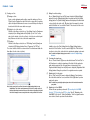
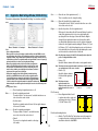
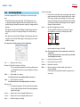
Note:
•When an image is printed out on a printer and then that image is cut by the Craft ROBO, the
positions of the printed image and the cut line must be matched. "Registration marks" are
the marks that are printed around the image, and they are used to match these positions.
The registration marks are shaped like the corners of a square (L), and are placed at three
locations enclosing the printed image. Depending on the printer model, the printable area
and the printing position with respect to the media may vary slightly. The
Craft ROBO reads the registration marks in order to confirm the position
of the printed image and then performs cutting at the correct position.
dSetting the origin Before data is cut by the Craft ROBO, the reference point for the cutting area
(the origin) can be changed. The origin represents a reference position in
the design from which all coordinates are calculated. Cursor coordinates can
be observed in the lower-right corner of the ROBO Master window while the
design is opened. In landscape orientation, the origin is at the left rear of the
Craft ROBO when viewed from the front. In portrait orientation, it is at the right
rear of the Craft ROBO as viewed from the front. That position is output so that
it corresponds to the lower left corner of the ROBO Master document.
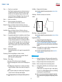
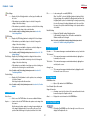
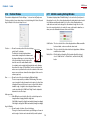
•When using registration marks, a fixed area around each registration
mark, shaded in the design area of ROBO Master, can't be printed.
When registration marks are used, therefore, make sure the object to be
printed, such as a picture or text string, does not interfere with the areas
shown in green in the figure at the right. However, cut data can be output
even for the green areas.
(1) Registration Mark Settings
First of all, create a new data file.
Next, to create registration marks, choose "Registration Mark Settings" from the
[Edit] menu to display the [Registration Mark Settings] window.
d-1 Use the [Blade Position] buttons on the Craft ROBO Controller screen to
move the blade to the position to be used as the origin.
d-2 When the position to be used as the origin is reached, click the [Set
Origin] button on the Craft ROBO Controller screen. That position
becomes the origin.
The "Orientation" setting selection determines the orientation of the design with
respect to the origin position. Please refer to the drawing of the Craft ROBO in
the upper-right corner of the Craft ROBO Controller screen.
(6) Cutting Click the [Cut...] button in the lower-right corner of the Craft ROBO Controller
screen. The Craft ROBO will begin cutting the outline.
Note:For details on using the Craft ROBO and the Craft ROBO Controller, please refer
to the Craft ROBO User’s Manual.
Select the "Use Registration Marks" check box, and then set the origin and other
registration marks parameters.
Note:For details on setting registration marks, please refer to Section 4.11,
"Registration Mark Settings Window (CC330-20 Only)".
Contents
Index
ROBO Master
OPS656
(2) Creating an ellipse
a Drawing an ellipse
Choose "Ellipse" from the [Draw] menu, and left-click at the point where the
center of the ellipse is supposed to be. Drag the mouse away from the center
point. An ellipse will be displayed as the mouse is moved. Reshape the ellipse
as desired, and click the mouse button again.
Choose "Solid" or "Gradient" for "Fill Type", and then click the [Modify Color]
button to select the color with which the ellipse is to be filled
Note:For details on gradient use, please refer to "Gradient" in Section 4.14, "Fill
Settings Window".
(3) Entering a text string
aEntering a text string
Choose "Text" from the [Draw] menu to display the [Text Settings] window. In
this window, set the "Font", "Width", "Height", and other parameters, and then
enter the text string (the Outline check box must be deselected). Click the [OK]
button. The text string will be displayed at the cursor position. Move the text
string into the ellipse, determine the position at which the text string is to be
placed, and then left-click the mouse.
bSetting the line color With the ellipse that was drawn in (a) selected, choose "Line Settings" from the
[Draw] menu to display the [Line Settings] window.
bSetting the text color
To change text color, with the text string selected, choose "Line Settings" from
the [Draw] menu to display the [Line Settings] window. Click [Modify...] in the
"Color" section, and select the desired text string (line segment) color. (Be sure
to select a color that is not being used for the cut line.)
Click [Modify...] in the "Color" section to display the "Color Settings" window,
and select the desired line color.
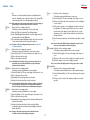
cAdjusting the text string Choose "Select" from the [Draw] menu, and then click the desired text string
to display a border enclosing the text string. In this state, the position or height
of the text string can be changed. After making the change(s), click any blank
space on the screen to deselect it.
Note:For details on editing the position or size of an object, please refer to "Select"
in Section 4.1.4, "Draw Menu", and to Section 4.16, "Position Window".
The screen should look like the one shown below.
cFill settings
With the ellipse that you drew selected, choose "Fill Settings" from the [Draw]
menu to display the [Fill Settings] window.
10
Contents
Index
ROBO Master
OPS656
(4) Creating a cut line
(5) Making the cut data settings
Choose "Output Settings" from the [File] menu to display the [Output Settings]
window. Choose the [Cutting Settings] tab in this window, and click the [Cutline
Settings] button. The [Cutline Settings] window will be displayed. Confirm that the
color specified for the cut line in (4) - b above (red in this example) is selected,
and that "Solid Cut Line" is selected for "Cutline". Then, deselect all other colors.
aDrawing a cut line
Create a cut line by drawing another ellipse around the existing one. Choose
"Ellipse" from the [Draw] menu, and left-click at the center point of the existing
ellipse. An ellipse will be drawn as the mouse is moved. Reshape the ellipse as
desired, and left-click the mouse button once again.
b Setting the color of the cut line
With the cut line ellipse selected, choose "Line Settings" from the [Draw] menu
to display the [Line Settings] window. Click [Modify...] in the "Color" section,
and select the desired color for the cut line (a color that is not used in the print
data). Red was selected for the cut line in the example below.
cFill settings With the cut line ellipse selected, choose "Fill Settings" from the [Draw] menu
to display the [Fill Settings] window. Choose "Transparent" for "Fill Type".
The screen should look like the one shown below. The red line drawn outside the
blue ellipse is the line to be cut (cut line).
In addition, choose the [Print Settings] tab in the [Output Settings] window,
deselect the "Print Cut Lines" check box, and click [OK]. If the "Print Cut Lines"
check box is selected, the cut line will also be printed when printing is performed.
Note:For details on Output Settings, please refer to Section 4.7, "Output Settings
Window".
(6) Previewing the output image
Choose "Preview" from the [File] menu, and switch between "Print" and "Cut" in
the [View] menu to confirm the output image. Check that all of the registration
marks have been printed. If all of the marks have not been printed, select
"Registration Mark Settings" from the [Edit] menu to display the [Registration Mark
Settings] window. Change the positions of the registration marks as required.
(7) Outputting the file to the printer Choose "Print" from the [File] menu to display the [Output to Printer] window.
Check that all the details are correct, and then click the [OK] button to perform
output on the printer.
Note:For details on operating the printer, please refer to the instruction manual for
your printer.
Note:In the screen shot, the cut line is drawn in a slightly enlarged size for easy
identification. The cut line can be drawn much closer to the outside contour of
the blue ellipse than shown here. Moreover, if the border of the ellipse (the black
line in this example) is unnecessary, the border can be specified as the cut line.
(8) Outputting to the Craft ROBO
Perform the same operations performed in "a Launching the Craft ROBO
Controller", "b Test plotting" and "c Test cutting" Step (5), "Outputting to the
Craft ROBO", of Section 3.3, "Cutting Text Outlines", from. As registration marks
are used here, follow the procedures described below.
11
Contents
Index
ROBO Master
OPS656
3.5 Cutting the Contour of a Printed Image (CC330-20 Only)
(9) Position alignment (Read registration marks) and cutting Load the media so that the side on which "Feed This Side First" is printed
between the registration marks is fed first into the Craft ROBO. Check that the
"Search Registration Mark" check box has been selected, and then click the [Cut...]
button at the lower-right corner of the Craft ROBO Controller screen. In this case,
registration mark reading and cutting are performed in succession. If the "Failed to Read Registration Marks" error message is displayed, move the
pen (blade) to the nearest registration mark and click the [Cut...] button once
again. If the "Failed to Read Registration Marks" error message is displayed again,
click the "Search Registration Mark " check box to deselect it, move the tool to
the nearest registration mark (within the small green square that is shown in the
image of the plotter displayed in the upper-right corner of the Controller screen),
and click the [Registration mark reading] button. When the registration marks have
been successfully read, click the [Cut...] button.
This section describes the procedure for loading and printing an image file, and cutting
the contour of the image.
Note: •The term "image data" refers to the data from an image file that has been loaded
into ROBO Master.
•The term "image file" refers to a data file consisting of pictures or photos (BMP,
TIF, JPEG and the like). Here, we'll create registration marks first, and then load an
image file.
(1) Registration Mark Settings
First of all, create a new data file.
Next, to create registration marks, choose
"Registration Mark Settings" from the [Edit]
menu to display the [Registration Mark
Settings] window. Select the "Use Registration Marks"
checkbox, and then set the origin and other
parameters of the registration marks.
Note:
• If the "Print Media Insertion Direction" checkbox has been deselected in the
"Registration Mark Settings" window, printing will not be performed.
• For details on using the Craft ROBO and the Craft ROBO Controller, please refer to
the Craft ROBO User's Manual.
Note:For details on setting registration marks,
please refer to Section 4.11, "Registration
Mark Settings Window (CC330-20 Only)".
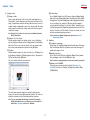
(2) Loading and adjusting an image
a Loading an image file Choose "File" from the [Insert] menu to display the [Load File] window. In this
window, specify the file to be loaded. An image border will be displayed on the
screen. Determine the location at which the image is to be placed, and then
left-click.
b Adjusting the image
If the image data has small squares
attached to its four corners, the
image data is in the selected
status. If it is not selected, choose
"Select" from the [Draw] menu and
click on the image data. When it is
in this status, the image data can
be moved or enlarged/reduced.
Note:For details on editing the
position or size of an object,
please refer to "Select" in
Section 4.1.4, "Draw Menu",
and to Section 4.16, "Position
Window".
12
Contents
Index
ROBO Master
OPS656
(3) Creating cut data
dCut data settings
Choose "Output Settings" from the [File] menu to display the [Output Settings]
window. Choose the [Cutting Settings] tab in this window, and click the [Cutline
Settings] button. The [Cutline Settings] window will be displayed. Confirm that
the color specified for the cut data in (3)- b above (red in this example) is
selected, and that "Solid Cut Line" is selected for "Cutline". In addition, choose
the [Print Settings] tab in the [Output Settings] window, and deselect the "Print
Cut Lines" check box. If the "Print Cut Lines" check box is selected, the cut line
will also be printed when printing is performed.
aDrawing a cut data
Create a cut line with which to cut the contour of the loaded image. Choose
"Rounded Rect." from the [Draw] menu, and then left-click at the top left of the
image, at a slight distance away from the image. When the mouse is moved, a
rounded rectangle is displayed. Move the mouse to the lower right of the image
until the image is enclosed by the rectangle, and then left-click once again to
complete the rectangle.
Note:[Polygon], [Circle], or other tools can also be used, in addition to [Rounded
Rect.], to draw cut data.
Note:For details on the [Output Settings] window, please refer to Section 4.7,
"Output Settings Window".
bSetting the color of the cut data With the rounded rectangle for the cut data selected, choose "Line Settings"
from the [Draw] menu to display the [Line Settings] window. Click the [Modify...]
button in the "Color" section, select the desired color for the cut data (red has
been selected in the example below) and then click the [OK] button.
(4) Outputting
aPreviewing the output image Click [Preview...] in the [Output Settings] window. Switch between "Print Image
Only" and "Cut Image Only" in the [View] menu, and confirm the image to be
printed and the image to be cut.
cFill settings With the rounded rectangle for the cut line selected, choose "Fill Settings" from
the [Draw] menu to display the [Fill Settings] window. Choose "Transparent" for
"Fill Type" and then click the [OK] button.
bOutputting to the printer Choose "Print" from the [File] menu to display the [Output to Printer] window.
After confirming the content, click the [OK] button to print.
The screen should look like the one shown below.
Note:For details on operating the printer, refer to the user's manual for your printer.
cOutputting to the Craft ROBO Perform the same operations described in Step (8), "Outputting to the
Craft ROBO", in Section 3.4, "Cutting a Text String Placed Inside an Ellipse
(CC300-20 Only)".
The red line drawn around the image is the cut data. For demonstration
purposes, the cut data is shown slightly larger than it really is. The cut line can
actually be created much closer to the image border than shown here.
Note:To cut out a pasted image, with the image selected, click [Clip Image] in
the [Edit] menu and then select a closed form tool such as a rectangle. For
details, refer to "Clip Image" in Section 4.1.2, "Edit Menu".
13
Contents
Index
ROBO Master
OPS656
3.6 How to Trace and Cut an Outline of an Image
(CC330-20 Only)
(3) Tracing an outline
aTracing an outline
With the image selected, choose "Get Outline" from the [Edit] menu to open
the [Auto Trace] window and display the selected image.
This section describes the procedure for loading an image file, tracing an outline of the
image, and then cutting the image by pasting in a cut line.
Note: The term "image file" refers to a data file consisting of pictures or photos (BMP, TIF,
JPEG and the like).
Here, we'll create registration marks first, and then load an image file.
(1) Registration Mark Settings
Perform the same operations as those performed in Step (1), "Registration Mark
Settings" of Section 3.5, "Cutting the Contour of a Printed Image (CC330-20
Only)".
(2) Loading and adjusting an image
Perform the same operations as those performed in Step (2), "Loading and
adjusting an image" of Section 3.5, "Cutting the Contour of a Printed Image
(CC300-20 Only)".
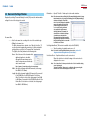
Set the Threshold, Thickness and other parameters, and then click the [Convert
to Outline] button to convert the displayed image to an outline.
Note:For details on how to trace the outline, please refer to Section 4.9, "Auto Trace
Window".
14
Contents
Index
ROBO Master
OPS656
3.7 For Easy Operation
bPasting the outline as a cut line
Select "Paste then Exit" to paste the outline as a cut line in the selected image.
Shortcuts are available for the following operations.
•Dragging with the right mouse button held down to specify an area.
•Areas can also be displayed in the preview screen in the same way by dragging with
the right mouse button held down.
•Pressing the [F2] key displays the entire medium.
•Pressing the [F3] key during an enlarged display enables the Move mode. The cursor
changes to the shape of a hand, allowing you to scroll the screen in any direction.
Hold down the left mouse button, and drag the mouse in the direction in which the
screen is to be moved. Press the [F3] key again to exit Move mode.
cSetting the color of the cut line
Perform the same operations as those performed in Step (3) - b, "Setting the
color of the cut data" of Section 3.5, "Cutting the Contour of a Printed Image
(CC300-20 Only)".
dCut line settings
Perform the same operations as those performed in Step (3) - d, "Cut data
settings" of Section 3.5, "Cutting the Contour of a Printed Image (CC300-20
Only)".
(4) Outputting
Perform the same operations as those performed in Step (4), "Outputting" of
Section 3.5, "Cutting the Contour of a Printed Image (CC300-20 Only)".
15
Contents
Index
ROBO Master
OPS656
4 Function Details
Close................ Closes the design that is currently being worked on.
Save................. Saves the currently opened design file while preserving the existing
file name.
4.1 Main Window
Save As............ When "Save As" is selected, the [Save As] window is displayed.
Specify the save location, specify a file name, and then click the [Save]
button to save the file.
Save to SD Card
. ........... When "Save to SD Card" is selected, the [Save to SD Card] window is
displayed.
Note: For details on the [Save to SD Card] window, please refer to Section 4.18,
"Save to SD Card Window".
Document Settings
. ........... Displays the [Document Settings] window.
Note: For details on the [Document Settings] window, please refer to Section 4.2,
"Document Settings Window".
Preferences...... Displays the [Preferences] window.
Note: For details on the [Preferences] window, please refer to Section 4.3,
"Preferences Window".
4.1.1 File Menu
Preview............. Displays an output image of the design to be printed or to be cut.
Note: For details on Preview, please refer to Section 4.4, "Preview Display".
New.................. Creates a new design. When "New" is chosen, the [Document Settings] window is displayed.
Set the parameters of the media according to the size and orientation
of the design to be created, and then click the [OK] button.
Print.................. Displays the [Print] window.
Note: For details on the [Print] window, please refer to Section 4.5, "Output to
Printer Window".
Craft ROBO...... Displays the [Output to Craft ROBO] window.
Note: For details on the [Document Settings] window, please refer to Section 4.2,
"Document Settings Window".
Note: For details on the [Output to Craft ROBO] window, please refer to Section
4.6, "Output to Craft ROBO Window".
Open................. Opens a saved design.
When [Open] is chosen, the [Open] window is displayed. After selecting
the file to be opened, click the [Open] button to open the selected file.
Output Settings
. ........... Displays the [Output Settings] window in which general settings for
output to the printer or Craft ROBO will be made.
Load DXF......... Loads DXF files in AutoCAD R13 format. The DXF objects that can be loaded are limited to line segments,
polylines, splines, circles, arcs, and ellipses.
Note: For details on the [Output Settings] window, please refer to Section 4.7,
"Output Settings Window".
Exit...................Closes the ROBO Master program.
Note: The term "DXF file" refers to an AutoCAD file format.
Thumbnail Browser
. ........... Calls up the [Thumbnails] window. A folder list and a preview screen are shown on the left side of the
[Thumbnails] window. Saved GSD designs and DXF files in a specified
folder are shown on the right side of the window. Double-clicking the
displayed image allows the file of that image to be loaded. To close the
[Thumbnails] window, click the [x] button at the upper right corner of
the window.
Note: The term "Thumbnail" refers to a file represented by its reduced image.
4.1.2 Edit Menu
Undo................. Reverts the immediately preceding editing operation.
Redo................. Re-executes the most recent operation that has been reverted by "Undo".
Cut.................... With a shape, text, or image selected, click [Cut...] to cut the selected
object from the screen.
Copy................. With a shape, text, or image selected, click [Copy] to prepare the
selected object for copying.
16
Contents
Index
ROBO Master
OPS656
Paste................ Pastes the cut or copied object. When [Paste] is clicked after an object is cut, the object is restored at
its original position. When [Paste] is clicked after an object is copied,
the border color of the copied object changes to yellow. Select that
object by left-clicking on it and dragging it. A copy of the same object
will appear. Move it to the desired position and then left-click.
Get Outline....... Displays the [Auto Trace] window.
Note: For details on the Auto Trace function, please refer to Section 4.9, "Auto
Trace Window".
Weld Shapes.....Welds the selected objects as shown below.
example:
Delete............... Deletes a selected object.
Mirror................ Creates a mirror image of the selected object. Both Horizontal Mirror and Vertical Mirror can be used.
Bring to Front.... Moves a selected object to the front of all objects on the screen. If filled objects overlap each other, select one to be placed at the front
and click [Bring to Front].
Send to Back.... Moves a selected object to the rear of all objects on the screen. If filled objects overlap each other, select one to be placed at the rear
and click [Send to Back].
Offset Shapes.....Displays the [Offset] window.
Note: For details on the Auto Trace function, please refer to Section 4.10, "Offset
Window".
Group................ Grouping allows multiple objects to be handled as one object. To group
objects, hold down the [Shift] key while clicking on the objects to be
included in a group. Click on each object in turn to select it (a large
rectangle enclosing the multiple objects selected will appear). While in
this state, click [Group]. The grouped objects can be edited by moving
or deleting them as one object. When a picture comprised of multiple
objects is created, group those objects so that they can then be easily
moved together.
Registration Mark Settings
. ........... Displays the [Registration Mark Settings] window.
Note: For details on the [Registration Mark Settings] window, please refer to
Section 4.11, "Registration Mark Settings Window (CC330-20 Only)". Registration marks cannot be used at the same time as the Weed Border
function.
Grid Settings..... The term "grid" refers to a grid of solid lines or dots displayed on the
screen, which serve as a guide for plotting.
Ungroup............ Ungroups grouped objects. To ungroup a grouped object, select a group to be ungrouped and click
[Ungroup].
Note: For details on the [Grid Settings] window, please refer to Section 4.12,
"Grid Settings Window".
Rotate Image.... Rotates an image 90 degrees each time it is clicked. Images can be rotated using three rotate commands: "Rotate 90°
CCW", "Rotate 180°", and "Rotate 90° CW".
4.1.3 View Menu
Fit...................... Changes the display range of the design currently being worked on,
along with the display scale, so that the entire media can be viewed.
Clip Image........ Clips an image.
(1)Use "Import File" from the Insert menu to load image data.
(2)While the loaded image data is selected, select the "Clip Image" check
box.
(3)The Clipping mode is entered. Select a closed shape such as Square,
Polygon, Closed Spline, or Ellipse to draw a shape on the image to be
cut out.
(4)Upon completion of drawing, click outside the image. The image that is
cut out in the form of the drawn shape will be displayed.
Zoom In............ Enlarges the display of the data currently being worked on.
Zoom Out.......... Reduces the display of the data currently being worked on.
Move................. Selecting "Move" enables Move mode, and selecting it once again
cancels Move mode. In Move mode, the cursor changes to the shape of a hand, allowing
the screen to be scrolled by dragging using the mouse, and allowing
the entire region of the media to be viewed.
Note: "Move" can be used only when the media is displayed in enlarged view.
When the entire media is being displayed, the displayed range cannot be
moved.
Note: If the clipping shape fully encloses the image, the entire image will be cut
out.
17
Contents
Index
ROBO Master
OPS656
4.1.4 Draw Menu
Tool Bar............ Specifies whether to show or hide the Tool buttons and the Tool Bar in
the main screen. If the mouse cursor is placed over the "Tool Bar", five lists of tools are
displayed: "Standard Tools", "Edit Tools", "Draw Tools", "Line Tools",
and "Fill Tools". Click on any tool to display it. The displayed tool is
flagged by a check mark.
Select......... This is the tool for selecting a previously drawn shape.
When a shape is selected, small square and/or triangle handles are
displayed around it. In this state, the operations described below can
be performed.
• Changing position
When the mouse cursor is placed over the shape, the cursor will
change to the shape of a hand. The position of the shape can be
changed by dragging it in this state.
Note: Each of the tool buttons is assigned the functions selected from the menu,
allowing any of these commands to be invoked by clicking on the tool
button. The assigned function of a tool button is displayed as a Tool Tip
(simple explanation) when the mouse cursor is placed over the tool button
for a few seconds.
• Editing the shape
When the mouse is placed on a small black square or triangle, the
cursor changes in shape to a bidirectional arrow. Dragging the mouse
in this status enables resizing with the width-to-height ratio locked. To
enable resizing with the width-to-height ratio unlocked, drag the mouse
while holding down a [Shift] key.
Status Bar......... Allows the status bar to be shown or hidden. The status bar is located at the bottom of the main window, and
displays the status and a simple explanation of each function.
Registration Marks
. ........... Specifies whether to display registration marks on the screen. This function can only be used when the "Use Registration Marks"
check box has been selected in the [Registration Mark Settings]
window.
• Rotating the shape
When the shape is clicked again, corner handles turn to small circles.
When the mouse cursor is placed over a circle handle, the cursor will
change shape to a bidirectional arrow ring. The shape can be rotated
by dragging it in this state.
Note: For details on registration marks, please refer to Section 4.11, "Registration
Mark Settings Window (CC330-20 Only)".
Print Area......... The "print area" is a printable range specified according to the media
size on the [Print Settings] tab of the [Output Settings] window, not
including the margins specific to the printer. When "Print Area" is selected, the printable area is displayed. The inner
area enclosed by the lines is the area where cutting can be performed.
Note: Imported images cannot be rotated this way. For details on rotating images,
please refer to "Rotate Image" in Section 4.1.2, "Edit Menu". Nor can
images be rotated when a line segment or image and a shape are grouped
together, or when an image and a shape are selected simultaneously.
Edit Point.... This is the tool for moving one of the bend points of a shape to change
its form. The effect of the [Edit Point] tool varies with each shape.
Print area
• Polyline, polygon, spline, and closed spline
Moving Anchor Point:
When one of these shapes is clicked, a black square handle is
displayed at each bend point, so dragging a handle, after left-clicking
on it to select it, allows the bend point to be moved as desired.
Margin
Cut Area........... Shows or hides the cut area.
The cut area is the area indicated by the thin red lines on the screen.
Add Anchor Point: Right-clicking on a line of the shape allows a bend point to be
added at the position of the click. Additional bend points allow more
flexibility in changing the shape of an object. Right-clicking on a
point allows the point to be deleted.
Note: Data that is outside the red lines will not be cut.
View Grid.........Displays a grid.
Note: The term "grid" refers to a grid of solid lines or dots displayed on the
screen, which serves as a guide for drawing.
Snap to Grid..... When "Snap to Grid" is selected, placing or moving of a shape aligns
it with a grid by snapping the red handle with the grid intersection.
Note: For splines and closed splines, a point cannot be moved to the same
coordinate as that of the point immediately preceding or following it.
Note: For details on the grid, please refer to Section 4.12, "Grid Settings Window".
View Meshes....Displays meshes of the carrier sheet when the "Use Carrier Sheet"
check box is selected.
18
Contents
Index
ROBO Master
OPS656
• Arc When an arc is clicked, small black squares are displayed at both
ends of it, allowing the start or end point of the arc to be changed. (The
center and radius of the arc are fixed during the procedure.)
Arc............. Selects the tool for creating an arc.
Follow the procedure specified below to create an arc.
(1)Select the [Arc] tool. The cursor will change to the shape of a cross.
(2)Click to specify the position of the center point of a circle including the
arc to be created.
(3)As the mouse is moved, a circle is displayed around the center point
specified above. The distance by which the mouse cursor is moved
from the center is the radius of the circle. When the circle is of the
desired size, click to confirm. The point at which you've clicked is the
start point of the arc.
(4)Move the mouse to draw an arc, and click at the end position to specify
it.
Note: When another shape (line segment, text, rectangle, circle, ellipse, image, or
grouped shape) is clicked, an object selection tool is invoked.
Text............ Selects the tool for creating a text string.
Follow the procedure specified below to create a text string.
(1)Select the [Text] tool to display the [Text Settings] window.
(2)In the [Text Settings] window, make the necessary settings, enter the
text string and then click the [OK] button.
(3)The entered text string will be displayed at the side of the cursor. Move
it to the desired location and click to specify the position.
Note: If you hold down the [Shift] key while specifying the end position of the
arc, the arc can be drawn in increments of 45 degrees.
Note: For details on the [Text Settings] window, please refer to Section 4.15,
"Text Settings Window".
Rectangle... Selects the tool for creating a rectangle.
Follow the procedure specified below to create a rectangle.
(1)Select the [Rectangle] tool. The cursor will change to the shape of a
cross.
(2)Click at one of the corners of the rectangle to be created to specify it.
(3)Click at the opposite corner of the rectangle to specify it.
Line............ Selects the tool for creating a line segment. Follow the procedure specified below to create a line segment.
(1)Select the [Line] tool. The cursor will change to the shape of a cross.
(2)Click on the start point to specify it.
(3)Click on the end point to specify it.
Note: If the [Shift] key is held while clicking on a point, the position that can
be specified as the end point will be limited to an angle in 45-degree
increments from the start point.
Note: If you hold down the [Shift] key while clicking, a square can be created.
Rounded Rect.
. ........... Selects the tool for creating a rounded rectangle.
Follow the procedure specified below to create a rounded rectangle.
(1)Select the [Rounded Rect.] tool. The cursor will change to the shape of
a cross.
(2)Click at one of the corners of the rounded rectangle to be created to
specify it.
Polyline...... Selects the tool for creating a polyline. Follow the procedure specified below to create a polyline.
(1)Select the [Polyline] tool. The cursor will change to the shape of a cross.
(2)Click on the start point to specify it.
(3)Sequentially click on passage points to specify them.
(4)Double-click at the position that is to be the end point.
Note: If you hold down the [Shift] key while clicking on a point, the position that
can be specified as a passage point or the end point will be limited to a
direction in 45-degree increments from the immediately preceding point.
Spline......... Selects the tool for creating a spline.
Follow the procedure specified below to create a spline.
(1)Select the [Spline] tool. The cursor will change to the shape of a cross.
(2)Click on the start point to specify it.
(3)Sequentially click on passage points to specify them. (Adjacent points
are linked with a spline.)
(4)Double-click at the position that is to be the end point. (Before
specifying the end point, at least two points including the start point
must be specified.)
Note: Passage points and the end point cannot be entered at the same
coordinate as that of the immediately preceding point.
19
Contents
Index
ROBO Master
OPS656
(3)Click at the opposite corner of the rounded rectangle to specify it.
Ellipse........ Selects the tool for creating an ellipse.
Follow the procedure specified below to create an ellipse.
(1)Select the [Ellipse] tool. The cursor will change to the shape of a cross.
(2)Click to specify the center point of the ellipse to be created.
(3)As the mouse is moved, an ellipse is displayed with the specified
point as the center point. When the mouse is moved in the vertical
direction the ellipse is enlarged in the vertical direction; when it
is moved in the horizontal direction the ellipse is enlarged in the
horizontal direction.
Note: If you hold down the [Shift] key while dragging, the ellipse will become a
circle.
Closed Spline
. ........... Selects the tool for creating a closed spline. Follow the procedure specified below to create a closed spline.
(1)Select the [Closed Spline] tool. The cursor will change to the shape of
a cross.
(2)Click at any point to start a closed spline.
(3)Click at another point to specify it. When the mouse is moved, the
displayed spline becomes looped.
(4)Specify successive passage points to draw a closed spline as desired.
(5)Double-click at the last point of the closed spline to finish.
Note: •Immediately after a rounded rectangle is created, a green circle is
displayed in it. Dragging that circle allows the roundness of the rectangle
to be adjusted.
•If you hold down the [Shift] key while dragging, a square with rounded
corners can be created.
Polygon...... Selects the tool for creating a polygon.
Follow the procedure specified below to create a polygon.
(1)Select the [Polygon] tool. The cursor will change to the shape of a
cross.
(2)Click at one of the corners of the polygon to be created to specify it.
(3)Sequentially click at the successive corners of the polygon to specify
them.
(4)Double-click at the last corner of the polygon.
Note: Passage points and the end point cannot be entered at the same
coordinate as that of the immediately preceding point.
Templates
. ........... Templates such as hearts that are often used are stored here.
These shapes can be freely called up and used in any design, and the
called up shapes can be edited in the same way as drawn shapes.
Follow the procedure specified below to call up the shapes.
(1)Select the [Templates] tool to display the shapes stored in ROBO
Master.
(2)Select the shape you want to use, and then double-click it with the
mouse.
(3)The selection window closes, and a frame representing the size of the
shape is displayed next to the mouse cursor.
(4)Move the cursor to the position at which the shape is to be placed, and
then click to finish.
Note: When square handles are displayed at each bend point of the polygon
immediately after its creation, the handles can be moved in order to finely
adjust the shape of the polygon. In addition, the [Edit Anchor Point] button
can be used to finely adjust the polygon later. If you hold down the [Shift] key while specifying points, the specifiable
position will be limited to a direction in 45-degree increments from the
immediately preceding point.
Circle.......... Selects the tool for creating a circle.
Follow the procedure specified below to create a circle.
(1)Select the [Circle] tool. The cursor will change to the shape of a cross.
(2)Click to specify the center point of the circle to be created.
(3)As the mouse is moved, a circle is displayed with the specified point
as the center point. The distance that the mouse is moved from the
center point determines the radius of the circle. When the circle is of
the desired size, click to finish.
20
Contents
Index
ROBO Master
OPS656
File.................... Loads an image file or metafile (WMF file).
When "Load File" is selected, the [Open] window is displayed. Select
the desired image file or metafile in the [Open] window, and then click
the [Open] button to place the loaded image. A rectangle representing
the size of the image for loading is displayed next to the cursor. Move
the cursor to the position at which the image is to be placed, and then
click to finish.
Line Settings
. ........... Displays the [Line Settings] window to set line types, line widths, and
line colors.
• If this window is opened while a shape is selected, it changes the
settings of the selected shape.
• If this window is opened while no shapes are selected, the line settings
are reflected on the shape to be created hereafter.
Metafile Settings
. ........... Displays the [Metafile Loading Settings] window. In this window, the display colors of the cutlines embedded into
Windows metafile can be changed.
Note: For details on the [Line Settings] window, please refer to Section 4.13,
"Line Settings Window".
Fill Settings
. ........... Displays the [Fill Settings] window for setting the fill of closed shapes.
Note: For details on the [Metafile Loading Settings] window, please refer to
Section 4.17, "Metafile Loading Settings Window".
• If this window is opened while a shape is selected, it changes the
settings of the selected shape.
• If this window is opened while no shapes are selected, settings are
reflected on the shape to be created hereafter.
4.1.6 Window Menu
Cascade........... This command rearranges non-minimized windows on top of each other.
Note: For details on the [Fill Settings] window, please refer to Section 4.14, "Fill
Settings Window".
Tile Horizontal
. ........... This command rearranges non-minimized windows by aligning them
horizontally on the screen.
Text Settings..... Displays the [Text Settings] window for setting text fonts and sizes.
• If this window is opened while a text string is selected, it changes the
settings of the selected text string.
Tile Vertical....... This command rearranges non-minimized windows by aligning them
vertically on the screen.
• If this window is opened while no text strings are selected, settings are
reflected on the text string to be created hereafter.
Arrange Icons
. ........... This command rearranges minimized windows by aligning them with
the lower left corner of the screen.
Note: For details on the [Text Settings] window, please refer to Section 4.15,
"Text Settings Window".
Position Settings
. ........... Displays the [Position] window to set the positions, sizes, and angles
of rotation of shapes. Selecting a shape enables this menu item.
4.1.7 Help Menu
ROBO Master hints
. ........... Opens a Tips window for the ROBO Master.
Note: For details on the [Position] window, please refer to Section 4.16, "Position
Window".
User's Manual... Opens this manual.
Support Information
. ........... Assuming connection to the Internet, this command launches the web
browser and opens the Graphtec web site.
4.1.5 Insert Menu
Select Source
. ........... Selects one of the TWAIN drivers for scanners enabled in Windows.
About................ Displays the version information of the ROBO Master.
Acquire............. Launches the selected TWAIN driver and captures a raster image from
the scanner. After the image has been captured, a rectangle representing the size
of the image is displayed next to the cursor. Move the cursor to the
position at which the image is to be placed, and then click to finish.
4.1.8 Craft ROBO Logo
. ........... Clicking the [Craft ROBO] icon at the lower right corner of the screen
displays the Graphtec web site.
21
Contents
Index
ROBO Master
OPS656
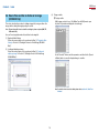
4.2 Document Settings Window
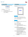
Orientation........ Specify "Portrait" or "Landscape" as the media orientation.
Note: If the document size specified in the [Document Settings] window is larger
than the media size set on the [Print Settings] tab of the [Output Settings]
window, selecting the "View Print
Area" check box displays the printable
areas on the media selected on the
[Print Settings] tab side by side so
as to cover the entire document
size specified in the [Document
Settings] window. For example, if a
document size of A4 and Landscape
orientation were selected in the
[Document Settings] window and A6
and Landscape orientation selected in
the [Print Settings] tab, the screen will
look like the one shown.
Displayed by selecting "Document Settings" from the [File] menu, this window enables
setting of the size of the design to be created.
Document Size
. ........... Sets the document size according to the size of the created design.
• Editing the document size To edit the document size as desired, select "Specify User Size..." To
use other than the designated document size, set the desired width
and length here, and select it in "Document Size" drop-down list.
The [Specify User Size] window has the following items.
Use Registration Marks (This function is available only for the CC330-20.)
. ........... Turns the printing of registration marks on or off.
Note: For details on the Registration Marks, please refer to Section 4.11,
"Registration Mark Settings Window (CC330-20 Only)".
Name: Select the name of the document which
width and length are to be edited.
Although the document name can be
edited, a document name that already
exists cannot be used.
Use Carrier Sheet…..Specifies whether to use the carrier sheet.
When this check box is selected, the image of the carrier sheet is
displayed on the screen.
Note: "Use Carrier Sheet" is always selected for the CC300-20 and this setting
cannot be changed.
Turning "View Mesh" allows you to confirm the cutting area using the
meshes of the carrier sheet displayed on the screen.
Note: Commas (,) cannot be used in a document name.
Width: Specify the document width in 0.01-mm units. (in the range
from 50.80 to 215.90 mm)
Length:Specify the document length in 0.01-mm units. (If your model
is the CC300-20, or the CC330-20 and the "Use Carrier
Sheet" check box is selected, the setting range is from 50.80
to 305.00 mm. If your model is the CC330-20 and the the "Use
Carrier Sheet" check box is not selected, the setting range is
from 50.80 to 1025.00 mm.)
22
Contents
Index
ROBO Master
OPS656
4.3 Preferences Window
4.4 Preview Display
This window is displayed when "Preferences" is selected from the [File] menu.
When "Preview" is selected from the [File] menu, the main window changes to the
preview display mode.
Cutting Plotter Model
. ........... Selects the model name of your Craft ROBO.
Unit................... Sets the unit used for dimensions.
Here, select "mm" or "inch". The unit specified here applies to all
dimensions in the ROBO Master.
4.4.1 Output Menu
Print.................. Outputs the data currently displayed in preview to a printer.
Craft ROBO...... Outputs the data currently displayed in preview to the Craft ROBO.
Close................ Closes the preview display mode.
4.4.2 View Menu
Fit...................... Changes the preview display range and scale so that the entire media
can be viewed.
Zoom In............ Enlarges the preview display.
Zoom Out.......... Reduces the preview display.
Print & Cut........ Changes the target to be displayed in preview. The image to be printed and the image to be cut are displayed on top
of each other.
Print Image Only... Changes the target to be displayed in preview. Only the image to be printed is displayed. If the "Print Cut Lines"
check box on the [Print Settings] tab of the [Output Settings] window
is selected, the image is displayed in preview along with the cut line.
Therefore, the display is the same as that for Print & Cut.
Cut Image Only... Changes the target to be displayed in preview. Only the output image for the Craft ROBO is displayed. The line
that has had its color selected (flagged by a check mark) in "Cutline
Settings" is displayed as the cut line.
Note: "Cut Image Only" cannot be selected if no colors are selected as cut lines
in [Cutline Settings].
23
Contents
Index
ROBO Master
OPS656
4.5 Output To Printer Window
4.6 Output to Craft ROBO Window
This window is displayed when "Print" is selected from the [File] menu.
This window is displayed when "Craft ROBO" is selected from the [File] menu.
Printer............... Displays the driver name and the output destination port of the
currently selected printer.
Craft ROBO...... Name: Displays the Craft ROBO driver. Port: Displays the destination port to which to output.
Copies.............. Specifies the number of copies. It can be specified in the range of 1 to 999.
Copies.............. Specifies the number of copies. It can be specified in the range of 1 to 999.
Page Range...... Specifies the pages to be printed. Select from two choices: "All" (all pages) or "From" (start page) and
"to" (end page).
Page Range...... Specifies the pages to be cut. Select from two choices; "All" or "From" and "to."
Note: "From" and "to" can only be selected when the data to be cut consists of
multiple pages (two or more pages).
Note: "From" and "to" can only be selected when the data to be printed consists
of multiple pages (two or more pages).
OK.................... Clicking the [OK] button launches the Craft ROBO Controller. When the [Cut...] button is clicked after the necessary operation is
performed using the Craft ROBO Controller, output to the Craft ROBO
is started. To stop output, click the [Cancel] button.
OK.................... The data currently being worked on is output to the printer.
24
Contents
Index
ROBO Master
OPS656
4.7 Output Settings Window
4.7.2 Common Settings
This window is displayed when "Output Settings" is selected from the [File] menu.
The content of settings made using the [Common Settings] tab are common to the
printer and the Craft ROBO.
4.7.1 Always Displayed Items
The following explains the items that are always displayed around the [Common
Settings], [Print Settings], and [Cutting Settings] tabs of this window.
Scaling.............. Enlarges or reduces the size of the shape to be output. This parameter can be specified in the range of 25% to 400%. The
value specified applies equally to height and width. If 25% is specified,
the shape will be 1/16 in terms of area ratio. The shapes and text that
were drawn and the loaded images are enlarged or reduced while
maintaining their aspect ratio. The media size will not be changed.
Printer............... Displays all of the printer driver names and their ports registered in
Windows. Specify the driver to be used for output to a printer.
Note: For details on the printer driver, please refer to the user's manual for your
printer.
Properties......... Displays a setup window for the printer driver for the selected printer.
Offset................ The output position is shifted by a specified length. A value for offset in the X (width) direction can be entered in the lefthand input box, and a value for offset in the Y (height) direction can
be entered in the right-hand input box. The specifiable offset varies
according to the media settings and so forth.
Craft ROBO...... Displays the Craft ROBO driver name and the output destination port.
Preview............. Confirms the content of the output settings that have been set and
displays the preview.
Output To Printer
. ........... Confirms the content of the output settings that have been set and
displays the [Output to Printer] window.
• When outputting to a printer If some data is shifted off the print area as a result of offset, the data
may be output separately in multiple sheets of media so that all data
will fit in the print area. In such a case, four sheets of media are output.
Output To Craft ROBO
. ........... Confirms the content of the output settings that have been set and
displays the [Output to Craft ROBO] window.
25
First Sheet
Second Sheet
Third Sheet
Fourth Sheet
Contents
Index
ROBO Master
OPS656
• When outputting to the Craft ROBO Only the data included in the print area is output. In this case, only the
yellow part shown in the figure at the under is output.
Media Size........ Specify the size of the media to be used for printing.
Orientation........ Specify the direction of the paper (printing direction).
Print Cut Lines
. ........... If this check box is selected, the lines that would be cut in "Output to
Craft ROBO" are also printed.
Rotate 180 degrees
. ........... If this check box is selected, the object is rotated 180 degrees and
then printed. This function is useful when the printer and Cutting Plotter margins
are different sizes, making the area for printing registration marks too
small (CC330-20 only).
Weed Border.... Cuts an outside border corresponding to the dimensions of the
document.
When a die-cutting sticker is created using media larger than the
document to be cut, use this function to peel off only the area required
for the sticker on the media. The size of the border is the same as that
of the document in the [Document Settings] window. The border can be
expanded in the horizontal and vertical directions by a specified size.
Specify the size in the range of 0.00 to 50.00 mm. If the size of the
border is expanded, the cut data is shifted from the cutting range by
an amount equal to the expanded
Loaded media
Expanded border
size, as shown below. If a smaller
(document size + specified size)
border is required, create cut data
for the outer border. If the "Weed
Original border
A
Border" check box is selected, the
A
Center shifted by an amount
equal to the expanded size
border is cut when the object is
cut.
4.7.4 Cutting Settings
Note: This function cannot be used at the same time as the Registration Mark
function (CC330-20 only).
Rotate............... Rotates the data for output. Select from "None", "90CCW", "180", or "90CW".
4.7.3 Print Settings
Note: This function cannot be used when registration marks have been set
(CC330-20 only).
Tiling................. Use this function for handling large amounts of data that exceed
the size of a single sheet of the media and you want to output it on
multiple pages. Page boundaries are always cut.
Note: This function cannot be used when registration marks have been set
(CC330-20 only).
• Media Size Enter the size of the media used.
26
When the media orientation is Landscape In the left-hand box, enter a value in the range of 50.00 to
1000.00 mm
In the right-hand box, enter a value in the range of 50.00 to
210.00 mm
Contents
Index
ROBO Master
OPS656
4.8 Cutline Settings Window
When the media orientation is Portrait In the left-hand box, enter a value in the range of
50.00 to 210.00 mm
In the right-hand box, enter a value in the range of
50.00 to 1000.00 mm
This window is displayed when [Cutline Settings] is clicked on the [Cutting Settings]
tab in the [Output Settings] window.
• Overlap Set a value in the range of 0 to 100 mm. If a value other than 0 is
specified for Overlap, pages are overlapped by a specified value
as they are cut. Use this function to create overlapping margins for
alignment when separated parts of an object are put together.
Cutline Settings
. ........... Calls up the [Cutline Settings] window. In the [Cutline Settings] window, specify any color for the cutline.
Dashed Line Pattern Settings
. ........... When thick media such as cardboard is folded, a fold line can be
added to facilitate folding. Furthermore, as this is a dashed line, it can also be used as a
perforation line.
Note: For details, please refer to Section 4.8, "Cutline Settings Window".
Note: The fold line is a dashed line. If the fold line is used for thin media, the
creased part of the media will become very weak. Therefore, consider the
quality and thickness of the media when using this function.
• Cut Segment Sets the length of the cut part of the fold line (dashed line) that is to be
cut. Specify it in the range of 0.1 to 100 mm.
• Spacing Sets the length of the uncut part of the fold line (dashed line) that is to
be left uncut. Specify it in the range of 0.1 to 100 mm.
Cutting Selection
. ........... Select the color of the "Solid Cut Line" or "Dashed Line". Only one type of line can be chosen for each color.
• Color Lists the colors of the outer lines of all shapes in the design. Because
all of the colors used are automatically specified for Solid Cut Line,
deselect all other colors, or those that are used for other than Solid
Cut Line.
• Cutline Select the "Solid Cut Line" or "Folding Line" to which a color from
the Color list is to be applied. Click on the Cutline parameter for each
color, and then make your selection from the pull-down menu. Lines in colors that were specified for "Solid Cut Line" will be cut by
the Craft ROBO as solid lines. Lines in colors that were specified for
"Folding Line" will be cut by the Craft ROBO as dashed lines.
27
Contents
Index
ROBO Master
OPS656
4.9 Auto Trace Window
Outer Frame Only
. ........... An outline is created using only the image data for the outer frame.
This window is displayed when "Get Outline" is selected from the [Edit] menu. When an image is being edited, click the "Convert to Outline" button to display the
"Convert to Outline" window. When an outline is being edited, click the "Edit Image"
button to display the "Edit Image" window.
Update.............. After the image has been converted to an outline, the outline can be
converted once again after making changes to the "Thickness" and
"Outer Frame Only" parameters.
<When an image is edited>
Show Background
. ........... Displays the original image in the background of the converted outline.
<When an outline is converted>
Convert to Outline/Edit Image
. ........... Click the [Convert to Outline] button to convert the contours of the
image data to an outline. Click the [Edit Image] button to enable the image to be edited or
redone if the converted outline is uneven or not displayed as expected.
Delete Break Point
. ........... Deletes any unwanted break points from the lines after the image data
has been converted to an outline.
Add Break Point
. ........... Adds break points to the lines after the image data has been converted
to an outline.
Threshold.......... The imported image is converted to monochrome image data, but
at that time discrimination between the black and white areas is
performed automatically. This discrimination between black and white
can be adjusted by changing the threshold value.
Straight/Curve... Changes straight lines to curved lines and vice versa after the image
data has been converted to an outline.
Paste then Exit
. ........... Exits the "Auto Trace" screen and pastes the outline in the layout
screen.
Thickness......... The contours of the image data are converted to an outline of the
specified width thickness only.
Note: For further details on the [Auto Trace] screen, please choose "Search Topics" from
the [Help] menu and then browse through the displayed topics.
28
Contents
Index
ROBO Master
OPS656
4.10 Offset Window
OK..................... The selected objects are offset according to the settings as shown
below. If you want to cancel offset, click the [Cancel] button.
Example: When offsetting a square by X mm outside using the miter
connection
This window is displayed when one or more objects are selected and "Offset Shapes"
is selected from the [Edit] menu.
X mm
Note: After offsetting, the original object that has been selected is deleted.
Offset Value...... Specifies the offset length by 0.01 mm unit. The available range for the
offset length varies according to the media settings and other settings.
Direction of Offset
. ........... Specifies whether to offset to the outside or inside of the selected
object(s).
Method of Join
. ........... Specifies the method to connect the offset lines when the offset to the
outside of the object(s) is selected.
Note: The offset lines are the lines that are moved in the offset length from the
original lines.
Miter...........The offset lines are connected at the intersection
that is specified as the extension of each offset line.
However, when the distance of the intersection point
and original connection point exceeds the specified
miter limit, it is clipped in the miter limit (length). In this
case, the lines are connected at the miter limit position
in the same manner as the Bevel connection.
The miter limit is specified by the multiplication with
offset length.
Round.........Each offset line is connected by arc which center is a
connection point and the radius is offset length.
Bevel...........Each offset line is connected by line.
29
Contents
4.11
Index
ROBO Master
OPS656
Registration Mark Settings Window (CC330-20 Only)
Size................... Shows the size of the registration mark ( L ). There is normally no need to change the setting.
This window is displayed when "Registration Mark Settings" is selected from the [Edit]
menu.
Width................ Shows the line width of the registration mark. The line width is fixed to "0.5 mm", and at this time there are no other
choices that can be selected.
Origin................ Specifies the position of the first registration mark. With respect to the media specified in Document Settings, the position
at which the registration mark is to be set can be determined by
specifying offsets from the edges of the media. When the Origin is
changed, the first registration mark moves to that position, and the
second and third registration marks move to the positions determined
relative to the first registration mark by adding the "Distance (1-2)" and
the "Distance (1-3)". In the left-hand input box, enter an offset value in
the horizontal direction of the media; in the right-hand input box, enter
an offset value in the vertical direction of the media.
When a "Orientation" is "Landscape"
When a "Orientation" is "Portrait"
Note:
•Notes on Registration Marks. When a printer is used to print an image on media and then the Craft ROBO is used to
cut out that image, the positions of the printed image and the cut line must be matched.
"Registration marks" are the marks that are printed around the image, and they are used
to match these positions. The registration marks are shaped like the corners of a square (L),
and are placed at three locations enclosing the printed image.
•When using registration marks, a fixed area around each registration
mark is not printed. When registration marks are used, therefore, make
sure the object to be printed, such as a picture or text string, does not
enter the areas shown in green in the figure below. However, cut data is
output even for the green parts of the figure.
•If the printer's margins prevent all the registration marks from being
printed, the Craft ROBO will not be able to read the registration marks
correctly. If this happens, change the origin point, the distance between
registration marks 1 and 2, and the distance between registration marks
1 and 3 to enable all the registration marks to be printed. The relationship
between the print area and the registration mark positions can be checked in the preview
menu.
Note: If the Origin was changed, click the [Fit to Document] button to adjust the
positions of Registration Marks 2 and 3.
• Distance (1-2) Specify the distance between the first and second registration marks.
Note: The distance between registration marks is the distance from the corner of
one registration mark to the corner of another.
Use Registration Marks
. ........... Turns the printing of registration marks on or off.
Distance between
points 1-2
Distance between
points 1-2
Origin
When a "Orientation"
is "Landscape"
Origin
When a "Orientation"
is "Portrait"
Fit to Document
. ........... Moves Registration Marks 2 and 3
to positions where they can be read,
and changes the values of "Distance
(1-2)" and "Distance (2-3)".
Mode................. Shows the registration-mark mode. The mode is fixed to "Use three marks", and at this time there are no
other choices that can be selected.
• Use three marks Reads three registration marks: the lower left, lower right, and upper
left corners of the media.
Mark................. Shows the registration mark pattern. The shape is fixed to "Pattern 2", and at this time there
are no other choices that can be selected.
Distance between
points 1-3
Note: The distance between
registration marks is the
distance from the corner of one
registration mark to the corner of
another.
Distance between
points 1-3
• Distance (1-3) Specify the distance between
the first and third registration
marks.
Print the media loading direction
. ........... Adds the "Feed This Side First" label and an arrow to the image that
is output on the printer to indicate the direction in which the media
should be inserted in the Craft ROBO.
Pattern 2
• Pattern 2 The corner of each registration mark faces the edges
of the media.
30
Contents
Index
ROBO Master
OPS656
4.12 Grid Settings Window
4.13 Line Settings Window
This window is displayed when "Grid Settings" is selected from the [Edit] menu.
This window is displayed when "Line Settings" is selected from the [Draw] menu. If
this window is opened while a shape is selected, use it to change the settings of the
selected shape. If this window is opened while no shapes are selected, the default
settings of a shape created hereafter are changed.
Show Grid......... Shows a grid.
Note: The term "grid" refers to a grid of solid lines or dots displayed on the
screen, which serve as a guide for drawing.
Snap to Grid..... When "Snap to Grid" is chosen, shapes are drawn or moved in
increments of grid spacing.
Line Type.......... Select a line type from the list. Six choices are available for selection: Solid Line, Dotted Line, Dashed
Line, Dotted/Dashed Line, Double-Dotted/Dashed Line, and None (the
line becomes transparent). These settings are only enabled for the onscreen or printed images.
• If you select "Snap to Grid" before drawing a shape, the shape will be
drawn in increments of grid spacing.
• If "Snap to Grid" is selected after the shape is created and the shape
is moved, the red corner handle is snapped to the nearest grid crosssection.
Note: Please refer to Section 4.8 "Cutline Settings Window" for the line types that
can be output to the Craft ROBO.
Line Width......... Select a line width. A numeric value can also be entered. Specify it in the range of 0.1 to
50.0 mm.
Note: Line Width can only be specified for Solid Line.
Modify............... Opens the [Color] window to enable setting of the line color.
Grid Type.......... Line: Light-gray lines are displayed at equal intervals in the horizontal
and vertical directions on the screen. Dot: Light-gray dots are displayed at equal intervals on the screen at
grid cross-sections.
Grid Spacing..... Sets the grid interval. Specify it in the range of 1 to 1000 mm in increments of 1 mm.
31
Contents
Index
ROBO Master
OPS656
4.14 Fill Settings Window
• Gradient The shape is filled with a color gradient.
This window is displayed when "Fill Settings" is selected from the [Draw] menu. If
this window is opened while a shape is selected, use it to change the settings of the
selected shape. If this window is opened while no shapes are selected, the default
settings of a shape to be created hereafter are changed.
Fill Type............. Selects a fill pattern.
• Transparent The shape doesn't have any fill and is comprised of outlines only.
Starting Color, Ending Color
. ........... Two colors of the gradient transition can be specified: one for the
start and one for the end of the gradient. (To specify colors, use the
respective [Modify Color...] buttons to open the [Color] window for the
Starting Color and the Ending Color). The gradient displayed in the window consists of the starting color in
the center and the ending color at both ends.
• Solid The shape is filled with a single color. Click [Modify Color...] to open
the [Color] window, and specify a fill color.
Move Horizontally
. ........... Sets the degree of gradient transition in the horizontal direction. As the slider is moved, the color transition border in the window
is scrolled to the left or right, depending on the direction of slider
movement.
Move Vertically
. ........... Sets the degree of gradient transition in the vertical direction. As the slider is moved, the color transition border in the window is
scrolled up or down, depending on the direction of slider movement.
Rotate............... Sets the rotation of gradient. As the slider is moved to the right, the gradient in the window rotates
to the left. As the slider is moved to the left, the gradient in the window
rotates to the right.
Color Window
32
Contents
Index
ROBO Master
OPS656
4.15 Text Settings Window
Use Mouse to Set Angle
. ........... If this check box is selected, the angle of a text string can be specified
using the mouse after its location is specified at the time of its creation.
As the mouse is moved, the placement angle of the character string
changes. Left-click at the chosen angle for final placement. At this time,
if you hold down the [Shift] key while moving the mouse the angle will
change in 45-degree increments.
This window is displayed when "Text" or "Text Settings" is selected from the [Draw]
menu.
•If "Text Settings" window is opened by clicking "Text" in the [Draw] menu, a box
for entering a text string is displayed at the bottom of the window. In this case, the
specified text string is created in the document according to the settings made in the
dialog box.
Space............... Specifies the spacing between characters. The spacing should be specified as a percentage (%). To leave a
space equivalent to one character, for example, specify 100%.
•If this window is opened by clicking "Text Settings" in the [Draw] menu while a textstring object is selected, use it to change the settings of the selected text-string
object.
A A B
•If this window is opened by clicking "Text Settings" in the [Draw] menu while no textstring objects are selected, the default settings of a text-string object to be created
hereafter are changed.
Note: Shown below is a window opened using "Text" in the [Draw] menu.
Equivalent to
one character
100%
Equivalent to
one character
Specify a number in the range of -50 to 400.
Note: •When a proportional font is used, be aware that spaces cannot be left at
equal intervals.
•The term "proportional font" refers to fonts for which the character width
differs depending on the character.
Italic.................. Sets the style of characters to "italic".
Bold.................. Sets the style of characters to "bold".
Font.................. Specifies the font of the text.
Underline.......... Underlines the characters.
Character Set... Specifies the character set of the font. This can normally be disregarded. Some fonts have multiple character
sets, allowing different characters to be presented by the selection of a
character set.
Outline.............. Shows the characters in outline form (with only the outlines of
characters displayed). If this check box is selected, Bold and Underline are grayed out and
cannot be set.
Width................ Sets the width of one character.
Note: With some fonts, the character width may differ for each character.
Height............... Sets the height of one character.
Note: With some fonts, the character height may differ for each character.
Hold aspect ratio
. ........... Used when making changes to the text string, this function maintains
the font's height-to-width proportions while automatically adjusting the
length of the text string.
X mirror............Creates a mirror of the text string with left/right reversed.
Y mirror............Creates a mirror of the text string with up/down reversed.
Angle................ Specifies the angle of a text string.
33
Contents
Index
ROBO Master
OPS656
4.16 Position Window
4.17 Metafile Loading Settings Window
This window is displayed when "Position Settings..." is chosen from the [Draw] menu.
Position can only be chosen when a shape is selected, allowing the Position, Size, and
Angle of Rotation of the selected shape to be set.
This window is displayed when "Metafile Settings" is chosen from the [Insert] menu. In
this window, the color of the cut lines displayed when the cutting data has been loaded
in the Windows metafile provided and the color of the cut lines displayed when an
outline has been traced can be changed. Use this window to change the color of the
lines to be converted when the color used is the same as that used for drawn lines, or
when you need to differentiate between cut lines and fold lines.
Solid Cut Line... The color selected for the cut lines displayed when a Windows metafile
has been loaded, or when an outline has been traced.
Position............. Shows the current position of the selected shape Width of the shape
using X and Y coordinates. The small red circle that is displayed when a
Height of
circumscribed rectangle has been drawn around
the shape
the shape and that shape is selected is the position
of the selected shape. Here, the origin is at the
Position of the shape
lower-left corner of the media. Numeric values
for coordinates can be entered directly from the keyboard to determine
the position of the shape. (If "Select Object" has been selected and the
mouse cursor is positioned on the screen, the coordinates of the current
mouse cursor position are shown at the lower right part of the screen for
reference purposes.)
Size................... Shows the size of the selected shape by Width and Height. The size is represented by coordinates. While drawing, if the mouse
cursor is moved in the direction away from the origin, a "positive" value
is displayed. Conversely, if the mouse cursor is moved in the direction
toward the origin, a "negative" value is displayed. Numeric values
can be entered directly for "Width" and "Height" from the keyboard to
determine the size of the shape.
Hold aspect ratio
. ........... When ON has been selected, the Size of the selected shape can be
changed without changing its width-to-height ratio. If the Width is changed, the Height is automatically changed accordingly.
If the Height is changed, the Width is automatically changed accordingly.
Angle of Rotation
. ........... Shows the angle of rotation of the selected shape. This angle is counted counterclockwise, up to 360 degrees. A num eric
value for angle of rotation can be entered directly from the keyboard.
Dashed Line..... The color selected for the dashed cut lines displayed when a Windows
metafile has been loaded.
Modify Color..... Click this button to display the [Color] window. Specify the desired
color for "Solid Cut Line" or "Dashed Line", and then click the [OK]
button.
34
Contents
Index
ROBO Master
OPS656
4.18 Save to SD Card Window
4.18.2 When saving in an SD card that already has the "Graphtec" folder
This window is displayed when "Save to SD Card" is selected from the [File] menu.
(1) Select the SD card in [Save in].
Note: To cut the data saved on an SD card using the Craft ROBO, files in GSP format must
be saved in the “Graphtec” folder in the root directory of the SD card. The files saved
in another location or saved in any other format than GSP cannot be cut.
4.18.1 When saving cutting data to an SD card for the first time (when
there is no "Graphtec" folder in the SD card)
(1) Select the SD card in [Save in].
In the example above, the SD card is inserted in the H drive of the computer.
(2) Double-click the “Graphtec” folder to open it.
In the example above, the SD card is inserted in the H drive of the computer.
(2) Click the [Create New Folder] button and create a folder named “Graphtec.”
Create the “Graphtec” folder right in the root directory of the SD card.
In the example above, the location of the “Graphtec” folder can be read as H (drive
name):\Graphtec.
(3) Enter a file name in [File Name], and click the [Save] button.
(3) Enter a file name in [File Name], and click the [Save] button.
35
Contents
Index
ROBO Master
OPS656
5 Printing the Register Mark Test Form
(CC330-20 Only)
(4) Select the [Register Mark Test Form] file, and click [Open]. The "Register Mark
Test Form" will be displayed.
This chapter describes the procedure for printing the registration mark test form that is
used in the Registration Mark Reading Test of the Craft ROBO.
(1) If the ROBO Master in your system was installed without changing the default
settings in "Choose Destination Location" and "Destination Folder", the "ROBO
Master" folder has been created in the location shown below.
(5) In the [Output Settings] window, select the printer to be used for printing and, if
necessary, change the "Print Settings". Open the [Output to Printer] window and,
after confirming the settings, click [OK] to print the Register Mark Test Form.
(2) Choose "Open" from the [File] menu of the ROBO Master to display the [Open]
window. For Look In, select the [ROBO Master] folder confirmed in (1) above.
Note: Use white, matte, A4-size paper for the Register Mark Test Form. Copy paper or the
like may be used. If possible, use the same media as will be used for cutting. This
may help increase the accuracy of registration mark reading.
(3) Select the [Adjustment] folder and click [Open].
36
Contents
Index
ROBO Master
OPS656
6 Error Messages
The registration mark positions are outside the specified
document area (CC330-20 only).
• The registration mark positions are outside the specified document area.
Operation-related Errors
Check Layout in the [Registration Mark Settings] window, and correct the
registration mark positions so that they will not extend past the document area.
A Media Name has not been specified.
• No media names are entered in the [Name] box of the [Specify User Size] window.
There is an error in the file contents.
Enter a media name in the [Name] box of the [Specify User Size] window that is
displayed by clicking [Specify User Size...] in the [Document Settings] window.
error occurred when a DXF-format file was loaded. The file may not be a DXF
• An
file.
Media Name ### has been reserved, and cannot be used.
Load the DXF file using the software with which it was created, and check the data.
•
The media name entered in the [Name] box of the [Specify User Size] window is
already in use.
No valid data.
• The DXF file contains no data that can be handled by the ROBO Master.
Enter a new name in the [Name] box of the [Specify User Size] window. A media
name can be registered only once.
The data in this file cannot be used.
### cannot be used as a Media Name.
This file format is not supported.
•
• The DXF file does not contain data that can be handled by the ROBO Master.
The media name entered in the [Name] box of the [Specify User Size] window
contains invalid characters.
This data cannot be used.
Commas (,) cannot be used in the [Name] box of the [Specify User Size] window.
Enter a new name.
File loading aborted.
[ESC] key on the keyboard was pressed while a saved file of the ROBO Master
• The
was being loaded.
Includes characters that cannot be used with the current font.
Please change the font.
text string entered in the [Text Settings] window is not supported by the current
• The
font or character set.
Do not press the [ESC] key until the system finishes loading the file.
Specify the corresponding font or character set for the text string entered in the [Text
Settings] window.
message is displayed when, for example, the system has failed to rewrite over
• This
an existing file.
Failed to launch the browser.
Remove write protection before saving, or save the data under another name.
A file cannot be created.
message is displayed when the Internet browser could not be started up
• This
normally.
Cannot write to file.
message is displayed when, for example, there is insufficient space on the
• This
hard disk.
Make sure your system is connected to the Internet.
Check the available space at the destination to which you are saving.
The overlap width exceeds the tiled plot area.
value specified for "Overlap" in Tiling is greater than the width or height of the
• The
Media Size.
Initialization failed. Cannot output.
Check whether Tiling on the [Cutting Settings] tab of the [Output Settings] window
is set properly. If it is not, correct the setting.
Check whether the device is connected.
• The printer driver for printing cannot be used.
37
Contents
Index
ROBO Master
OPS656
Output failed.
File Loading Errors
•
This file format is not supported.
This message is displayed when data could not be output to the Craft ROBO
normally.
• Loading of a file format that is not supported was attempted.
Check to confirm that the Craft ROBO is connected properly and that its standby
switch is turned on.
The file specified cannot be loaded.
The header information contains an error.
Output aborted.
• The file header information contains an error.
• The Craft ROBO Controller has already been launched.
The file specified cannot be loaded.
Close the Craft ROBO Controller that has already been launched, and then perform
the operation once again.
The file was incorrectly compressed.
• The file format to be loaded contains an error.
Craft ROBO Controller startup failure.
• The Craft ROBO Controller could not be launched.
The file specified cannot be loaded.
Check whether the "Craft ROBO Controller" has been installed in your system. If it has not been installed, install it from the CD included with your Craft ROBO.
Tile-divided files cannot be read.
Files compressed using LZW cannot be read.
CALS Type 2 files cannot be read.
Files compressed using CCITT 2D cannot be read.
INTERGRAPH Uncompressed files cannot be read.
INTERGRAPH RLE files cannot be read.
Cannot find the Craft ROBO driver. Please install the driver.
• The "Craft ROBO Driver" is not installed.
Install the "Craft ROBO Driver" using the CD included with the Craft ROBO.
preceding error messages appear if you attempt to load a file with a file format
• The
not supported by ROBO Master.
Twain Errors
An error occurred in the TWAIN device.
The file specified cannot be loaded.
• An error occurred in the TWAIN device selected in the Model Setup dialog box.
Failed to update the image. The image cannot be rotated.
Check the TWAIN device's connections.
message is displayed during the rotation of an image. More specifically, it
• This
is often displayed when the available space in memory or on the hard disk is
Loading was aborted.
• The [ESC] key on the keyboard was pressed during the loading of an image file.
insufficient.
Terminate other active software and delete unnecessary files in order to increase
the available space on the hard disk.
Do not press the [ESC] key until the system finishes loading the file.
The specified image is not supported.
Cannot load the specified Metafile.
• The TWAIN device output a file format that cannot be read in this software.
message is displayed when loading of a metafile-format file not supported by
• This
ROBO Master is attempted.
In the TWAIN device settings, set it up to output a bilevel image, an 8-bit grayscale
or color image, or a 24-bit color image.
The system cannot load the specified file.
38
Contents
Index
Index
A
About ...................................... 21
Acquire ................................... 21
Add Break Point . .................... 28
Angle ...................................... 33
Angle of Rotation .................... 34
Arc .......................................... 19
Arrange Icons ......................... 21
Auto Trace Window ................. 28
B
Basic Operations ....................... 6
Bevel . ..................................... 29
Bold ........................................ 33
Bring to Front . ........................ 17
C
Cascade ................................. 21
Character Set ......................... 33
Circle ...................................... 20
Clip Image .............................. 17
Close ................................ 16, 23
Closed Spline ......................... 20
Color of the Cut Data . ............ 13
Color Window ......................... 32
Common Settings ................... 25
Convert to Outline .................. 28
Copies .................................... 24
Copy ....................................... 16
ROBO Master
OPS656
Craft ROBO ......... 16, 23, 24, 25
Craft ROBO Controller . ............. 8
Craft ROBO Logo ................... 21
Cut .......................................... 16
Cut an Outline of an Image .... 14
Cut Area ................................. 18
Cut Data, Creating . ................ 13
Cut Data settings .................... 13
Cut Image Only ...................... 23
Cutline Settings ...................... 27
Cutline Settings Window . ....... 27
Cutting ....................................... 9
Cutting Plotter Model .............. 23
Cutting Selection .................... 27
Cutting Settings ...................... 26
Ellipse ............................... 20, 29
Ending Color . ......................... 32
Error Messages ...................... 37
Exit ......................................... 16
Exiting . ...................................... 6
F
Features .................................... 3
File . ........................................ 21
File Menu . .............................. 16
Fill Settings ....................... 13, 21
Fill Settings Window ............... 32
Fill Type .................................. 32
Fit ..................................... 17, 23
Fit to Document ...................... 30
Font ........................................ 33
Function Details . .................... 16
D
Dashed Line ........................... 34
Dashed Line Pattern Settings 27
Delete ..................................... 17
Delete Break Point . ................ 28
Direction of Offset . ................. 29
Document Settings ................. 16
Document Settings Window ... 22
Document Size ................. 22, 23
Draw Menu ............................. 18
G
Get Outline ............................. 17
Gradient . ................................ 32
Grid Settings . ......................... 17
Grid Settings Window ............. 31
Grid Spacing . ......................... 31
Grid Type ................................ 31
Group ..................................... 17
H
E
Height ..................................... 33
Help Menu .............................. 21
Hold Aspect Ratio . ........... 33, 34
Easy Operation . ..................... 15
Edit Image .............................. 28
Edit Menu ............................... 16
Edit Point ................................ 18
39
I
Image, Adjusting . ................... 12
Image Data ............................. 12
Image File . ....................... 12, 14
Image File, Loading ................ 12
Initial Steps ................................ 7
Insert Menu ............................ 21
Installing .................................... 5
Introduction . .............................. 3
Italic ........................................ 33
L
Launching .................................. 6
Line . ....................................... 19
Line Settings . ......................... 21
Line Settings Window ............. 31
Line Type ................................ 31
Line Width . ............................. 31
Load DXF ............................... 16
M
Main Window .......................... 16
Mark ....................................... 30
Media Size . ............................ 26
Metafile Loading
Settings Window .................. 34
Metafile Settings ..................... 21
Method of Join ........................ 29
Mirror ...................................... 17
Miter ....................................... 29
Mode ...................................... 30
Modify ..................................... 31
Contents
Index
Modify Color ........................... 34
Move . ..................................... 17
Move Horizontally ................... 32
Move Mode . ........................... 15
Move Vertically ....................... 32
N
New ........................................ 16
O
Offset ................................ 25, 29
Offset Value ............................ 29
Open . ..................................... 16
Orientation . ...................... 22, 26
Origin . ................................ 9, 30
Outer Frame Only ................... 28
Outline .................................... 33
Output . ................................... 13
Output Menu . ......................... 23
Output Settings . ..................... 16
Output Settings Window ......... 25
Output to Craft ROBO ............ 25
Output to
Craft ROBO Window . .......... 24
Output to Printer ..................... 25
Output to Printer Window ....... 24
Overlap ................................... 27
P
Page Range . .......................... 24
Paste ...................................... 17
Paste then Exit ....................... 28
ROBO Master
OPS656
Points to Note ............................ 3
Polygon . ................................. 20
Polyline ................................... 19
Position ................................... 34
Position Settings ..................... 21
Position Window ..................... 34
Preferences ............................ 16
Preferences Window . ............. 23
Preview ............................. 16, 25
Preview Display ...................... 23
Print .................................. 16, 23
Print & Cut .............................. 23
Print Area ............................... 18
Print Cut Lines . ...................... 26
Printed Image, Cutting . .......... 12
Printer . ............................. 24, 25
Print Image Only . ................... 23
Print Settings .......................... 26
Print the Media Loading Direction Rotate ............................... 26, 32
Rotate 180 degrees ................ 26
Rotate Image .......................... 17
Round ..................................... 29
Rounded Rect. . ...................... 19
S
Save ....................................... 16
Save As .................................. 16
Save to SD Card . ................... 35
Scaling . .................................. 25
Select ..................................... 18
Select Source ......................... 21
Send to Back .......................... 17
Shortcuts ................................ 15
Show Background .................. 28
Show Grid . ............................. 31
Size .................................. 30, 34
Snap to Grid ..................... 18, 31
Solid ....................................... 32
Solid Cut Line ......................... 34
Space ..................................... 33
Spline ..................................... 19
Starting Color ......................... 32
Start Window ............................. 4
Status Bar . ............................. 18
Straight/Curve ........................ 28
Support Information . .............. 21
System Requirements ............... 3
30
Properties ............................... 25
R
Rectangle ............................... 19
Redo ....................................... 16
Registration Marks ................. 18
Registration Mark
Settings . ........................ 12, 17
Registration Mark
Settings Window .................. 30
Registration Mark Test Form .. 36
ROBO Master hints ................ 21
T
Templates ............................... 20
40
Test Cutting ............................... 8
Test Plotting ............................... 8
Text ......................................... 19
Text Outlines, Cutting ................ 7
Text Settings ........................... 21
Text Settings Window ............. 33
Thickness ............................... 28
Threshold ............................... 28
Thumbnail Browser ................ 16
Tile Horizontal ........................ 21
Tile Vertical ............................. 21
Tiling ....................................... 26
Tool Bar .................................. 18
Tracean Outline of an Imag .... 14
Transparent ............................ 32
U
Underline ................................ 33
Undo ....................................... 16
Ungroup . ................................ 17
Unit ......................................... 23
Update .................................... 28
Use Carrier Sheet . ................. 22
Use Mouse to Set Angle . ....... 33
User's Manual . ....................... 21
Use Registration Marks .... 22, 30
V
View Grid ................................ 18
View Menu . ...................... 17, 23
View Meshes .......................... 18
Contents
Index
ROBO Master
OPS656
W
Weed Border .......................... 26
Weld Shapes .......................... 17
Width ................................ 30, 33
Window Menu . ....................... 21
X
X mirror . ................................. 33
Y
Y mirror . ................................. 33
Z
Zoom In ............................ 17, 23
Zoom Out ......................... 17, 23
The specifications, etc., in this manual are
subject to change without notice.
OPS656m-UM-155
May 30, 2008
GRAPHTEC CORPORATION
41