1
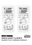
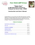
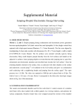
Nenad Rotter, 9A5N
9A5N Solid State CW Paddle
User manual
Table of contents:
1. General description
2. Before you begin
3. Finger piece and/or battery installation
4. Interconnection
5. Lever(s) sensitivity adjustment
6. Auto switch off
7. Contest mode
8. Troubleshooting
9. Transport
10. Specification
11. Warranty
[email protected]
Nenad Rotter, 9A5N
1. General description
Thank you for purchasing the Solid State CW Paddle. It should provide many
hours of CW keying pleasure for years to come.
The Solid State CW Paddle is a very sensitive instrument, having no moving
parts, which will give you a new sense of CW keying.
Advantages of the Solid State CW Paddle:
• stationary lever(s) having no travel time and no inertia of motion
• necessary keying force on the lever(s) is reduced
• finger movements are diminished
• keying is absolutely silent, without the clicking sound so characteristic of
mechanical paddles
• the lack of mechanical contacts eliminates cleaning, adjustments and
bouncing
• lever sensitivity adjustment is done by a software algorithm and no tools are
required
• no maintenance
The keying technique for the Solid State CW Paddle is equivalent to that
required for mechanical paddles. Users will rapidly adjust their keying style to gain
the advantages of the Solid State CW Paddle and increase their maximum keying
speed with ease. Since less finger pressure is necessary on lever(s) and finger
movements are diminished, keying will be less fatiguing and more enjoyable.
The Solid State CW Paddle has two major parts: head and base.
The paddle “brain” based on microcontroller technology is situated in the head,
which is made of aluminum to protect sensitive electronic components from the
effects of RF signals.
The paddle base is a piece of stainless steel/coated steel with a mass of 1.5 kg.
The total paddle mass of 1.8 kg gives outstanding paddle stability on flat surfaces
during keying.
In order to generate CW code, an external keyer or a transceiver with built-in
keyer must be used.
The Solid State CW Paddle is available in a single and twin lever version.
ATTENTION:
Avoid exposing the paddle lever(s) to any excessive pressure or shock.
Excessive pressure can drastically reduce the lifetime of sensors internal to the
lever(s) while stronger shocks can cause permanent damage.
[email protected]
Nenad Rotter, 9A5N
2. Before you begin
The Solid State CW Paddle is delivered without batteries and an interconnection
cable, mainly due to the paddle’s shipping weight. In order to keep the paddle as
heavy as possible and still limit the mass to a maximum of 2 kg for delivery as a
registered letter to your address, no batteries or cables are included in the package.
In order to prepare the Solid State CW Paddle for operation, you will need to
obtain the following:
• battery AAA (LR03) type - 2 pcs
• an interconnection cable
The installation of the battery and interconnection is described below:
The button on the right side of the paddle is the on / off switch. The paddle
status is indicated by a blue LED behind a white window under the lever(s).
The button acts as a toggle:
To switch the paddle on, push the button until the LED turns on.
To switch the paddle off, push the button until the LED turns off.
The switch off action takes around 0.5 second to avoid involuntary paddle offs.
Remember to retain your original Solid State CW Paddle box for future
transport (e.g. portable operation, DX expeditions, etc.) and/or for secure paddle
storage.
3. Finger piece and/or battery installation
If your paddle is sent to you via post, the finger piece(s) are not mounted on the
lever(s) to avoid lever sensor damage during shipment and batteries are not inserted
due to postal service safety regulations.
As finger piece montage on lever(s) and battery insertion can be done at the
same time, the procedure below describes both.
To reach the battery compartment it will be necessary to separate the paddle
base and head, which are connected together with 4 screws. In addition, the
installation of the finger piece(s) is safe and easy when the paddle base and head have
been separated.
For this task you will need: a Phillips screwdriver (a magnetic tip is
recommended) and a book that is at least 5 mm thick. A hex key for finger piece
screws is attached.
Note that a finger piece, once attached, will be higher than the paddle head and
that the paddle should not be placed upside down on a flat surface without using the
book.
ATTENTION:
Always check the + or - direction of batteries before insertion, as batteries
inserted with the wrong polarity will cause permanent damage to paddle
electronics.
Sensors on lever(s) are very sensitive to excessive pressure. Special care
should be taken during finger piece screw tightening.
[email protected]
Nenad Rotter, 9A5N
Procedure:
1. Place the book on the table.
2. Turn the paddle upside down and place the head on the book taking care
that any installed finger pieces are free in the air.
3. Remove 4 screws.
4. Lift up the base.
If you are only installing/replacing the batteries, continue with step 8.
5. Remove protective foil from finger piece if not removed already and insert
screws into finger piece holes. For the twin lever version, take care to put
each finger piece on the correct side. Screw heads should be on the side
having rounded edges.
6. Align finger piece to lever so that screws can touch threads on lever. Take
the hex key and turn one screw a little. Always turn gently and apply as
little pressure on the lever as possible. When the first screw is halfway in,
repeat with the second screw. Turn screws alternately until completely in
but not yet tight. On the twin version, repeat for the second lever.
7. Check finger piece(s) and lever alignment(s) and tighten screws gently. On
the twin version, also check the alignment of the two finger piece edges
and then tighten screws gently on both finger pieces.
[email protected]
Nenad Rotter, 9A5N
8. Put batteries in holder, while taking care that the polarity is correct.
9. Press the on / off button and switch on paddle. If the paddle doesn’t switch
on, rotate the batteries in the holder with your fingers and try again.
10. When the paddle switches on, press the button again and switch off paddle.
11. Place the base back on the head and align holes on the base with holes on
the head.
12. Put screws one by one into the base holes and turn a little. If the
screwdriver tip is magnetic this task will be very easy.
13. When all 4 screws are in place, screw them in completely and tighten
gently.
14. Turn paddle over to its normal position.
Battery lifetimes depend on quality and usage, but generally, should last for
approximately 800 operating hours for the single version and 600 operating hours for
the twin version. The paddle will still operate with very low battery voltage; as a
result, batteries should be replaced to avoid acid leakage.
The intensity of the blue LED light reflects the battery state. When weak or
invisible it is time to change the batteries.
ATTENTION:
Never leave batteries in the paddle if stored long term.
[email protected]
Nenad Rotter, 9A5N
4. Interconnection
On the back of the Solid State CW Paddle there is a 3.5 mm 3-pin (“stereo”)
socket for connection with external devices (such as a keyer or transceiver with a
built-in keyer).
For interconnection between the Solid State CW Paddle and an external device,
a two-wire shielded cable must be used.
Users can easily make their own cable to the required length.
To use, one cable end must go into the Solid State CW Paddle’s, 3.5 mm 3-pin
(“stereo”) phone plug.
The plug pin outs are:
Tip – left lever, or left side of single lever, normally Dot out
Ring – right lever, or right side of single lever, normally Dash out
Shaft – common
At the other cable end, the type of plug and pin outs depend on the device to be
used. You may want to consult the device user manual for these details.
In most cases (where the pin outs are the same on both the paddle and the
external device) prefabricated shielded audio cable with a 3.5 mm stereo plug on both
ends can be used. If the external device has a 6.3 mm paddle socket, a “stereo”
adapter from 3.5 mm to 6.3 mm may be used.
Some telegraphers may prefer to use a reversed Dot / Dash paddle
configuration. If this is the case, the interconnection cable should be reversed at one
end. It is also possible to use a straight cable with the external device set to a reversed
paddle configuration.
The Solid State CW Paddle outputs are of semiconductor type. Outputs will
work properly if a positive voltage to common is present on the Dot and Dash line.
Most electronic keyers and transceivers have +5 V present on Dot / Dash input lines
while the current to common is 1 mA or less.
Paddle outputs can handle voltages up to 50 V and current up to 10 mA.
[email protected]
Nenad Rotter, 9A5N
5. Lever sensitivity adjustment
The only thing that users can adjust on the Solid State CW Paddle is lever
sensitivity to the finger pressure required to close paddle outputs. When sensitivity is
higher, a lower finger pressure is required on the lever to close paddle outputs and
vice versa, when sensitivity is lower, a higher finger pressure is required on the lever
to close paddle outputs. The sensitivity of lever sides in the single version or levers in
twin version are always equal and cannot be changed separately.
The Solid State CW Paddle has been delivered preset to the highest lever
sensitivity. This may be too high for some users, especially when beginning paddle
use and such users may want to reduce it. Sensitivity can be adjusted in a range from
10 grams to 50 grams approximately, in 8 steps - with 5 grams to each step.
Correct lever sensitivity is very important for correct CW keying and every user
should select the sensitivity that is most suitable for him/her.
The Solid State CW Paddle lever sensitivity adjustment is done by a software
algorithm and requires no other tools. Lever sensitivity can be changed at any time,
taking just a few seconds.
When the software algorithm for lever sensitivity adjustment has been activated,
the paddle outputs become temporarily inactive. The lever(s) and LED function allow
changes to sensitivity with the following functions:
• a short push to the right side of the lever (or the right lever) will decrease the
sensitivity by one step and the LED will confirm the lever push with a long
blink
• a short push to left side of the lever (or the left lever) will increase the
sensitivity by one step while the LED will confirm the lever push with a
short blink
• three short LED blinks after a lever push indicates that the high or low
sensitivity limit has been reached
To start the software algorithm for lever sensitivity adjustment, perform the
following procedure:
1.
2.
3.
4.
5.
Switch on paddle if it is not already on
Push the on / off button and keep it pushed in
The LED will turn off and 2 seconds later, will briefly blink 3 times
Release the on / off button
The LED will blink again. The paddle is now in sensitivity adjustment
mode.
At this point you will be able to change the sensitivity with pushes to the
lever(s) as described by the functions above. Count the LED confirmation blinks. This
number will give you information on the extent to which you have changed the
sensitivity. If you want to change the sensitivity rapidly, push the desired side of the
lever (or the desired lever) and keep it pressed. The sensitivity will then change at a
rate of 1 step per second. Count the LED confirmation blinks, as that tells you by how
much the sensitivity has changed. When the sensitivity has been changed by the
required numbers of steps to a new value, the paddle should be turned back to normal
operational mode, to check the new lever sensitivity.
[email protected]
Nenad Rotter, 9A5N
To stop the software algorithm for lever sensitivity adjustment, push the on / off
button until the LED turns on, which indicates normal paddle mode operation. You
can then check the new lever sensitivity. If the required sensitivity has not been
achieved, repeat the adjustment procedure as many times as necessary.
The value of the lever(s) sensitivity is permanently saved in the
microprocessor's EEPROM and will not change until adjusted again.
6. Auto switch off
If no paddle lever is pressed for approximately 40 minutes, the Solid State CW
Paddle will switch off automatically.
7. Contest mode (S/N: MMXIV 052 and up)
During CW contests, paddles are used infrequently, but should be permanently
ready 24/48 h to commence immediate keying. As paddles may also be unused for
periods longer than 40 minutes, the Auto switch off function should be temporarily
disabled.
Procedure:
1. Switch off paddle if it is not already off
2. Push the on / off button and keep it pushed
3. The LED will turn on start blinking 2 seconds later
4. Release the on / off button
5. The LED will turn on and stay on. This indicates that the paddle is in contest
mode and will remain so unless the user switches it off manually.
Contest mode is canceled when the paddle is switched off.
ATTENTION:
Do not forget to switch off paddle manually after entering contest mode,
because otherwise the paddle will remain on until the batteries have discharged
completely.
8. Troubleshooting
If the Solid State CW Paddle starts to key out Dots or Dashes by itself, simply
switch it off and on.
If you experience some other kind of malfunction, please report it to the
manufacturer.
ATTENTION:
The Solid State CW Paddle may work improperly if a very strong RF field
is present in the ham shack.
[email protected]
Nenad Rotter, 9A5N
9. Transport
Do paddle transport in original paddle box, always.
ATTENTION:
It is highly recommended to dismantle finger piece from lever(s) before
transport to avoid possible lever sensors damage in case of rough handling with
the box.
Never leave batteries in the paddle if sending by the post.
10. Specification
Dimensions:
Base material:
Head material:
Finger piece material:
Total weight:
Lever sensitivity:
Paddle outputs:
Supply:
Batteries lifetime:
Sensors lifetime:
90 x 90 x 60 mm
stainless steel/coated steel
anodized aluminum
Plexiglas, other materials on request
1.8 kg
adjustable in range from 10 g to 50 g
50 V / 10 mA max.
2 x AAA (LR03) batteries
Single version – 800 h
Twin version – 600 h
depending on battery quality
100 million pushes, approximately
11. Warranty
The warranty period for the Solid State CW Paddle is 24 months from date of
purchase and covers defects in material or workmanship, with the exception of lever
sensors.
Mechanical damage to the paddle, or failure in paddle electronics as a result of
battery insertion with the wrong polarity, will invalidate the warranty.
[email protected]