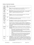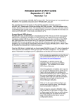
1
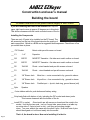
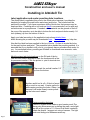
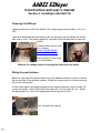
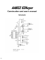
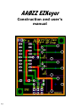
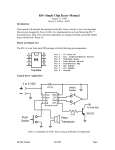
AAØZZ EZKeyer
Complete Construction and
User’s Manual
Introduction
Specifications & Features
Building the Board
Installing in Altoids® Tin
Using the Keyer
Command List
Schematic diagram
PCB overlay
Technical Stuff - Craig Johnson AAØZZ
Other Stuff - Terry Fletcher, WAØITP.
Page 1
AAØZZ EZKeyer
Construction and user’s manual
Introduction
Note: This is a very simple kit to build, and if you are an experienced
builder you may wish to build the board and jump ahead to Section 4.
Section 4 is intended to be an Altoids tin tutorial for those who haven't
used one before, or have had difficulty preparing the tins in the past. So if
you‟re good at using Altoids tins, you may wish to just print out your label,
install it and the board and and jump to Section 5.
Before beginning the assembly please print out the Altoids label of your
choice from this page and also the bottom insulator from here
This full featured PIC-based iambic Morse code keyer features 3
memories and very easy use. It has many of the features of the high end
keyers while maintaining ease of use. The PIC chips have been
programmed by Craig Johnson, AAØZZ, of PIC-EL fame. Commands are
entered directly rather than scrolling through menus.
Using a PC board that is only 1.5" x 1.75", this is an EZ-to-build small
footprint project with large impact on your operating capabilities, whether
in the shack or in the field. It is Altoids® tin compatible, and installation
instructions are included in the assembly manual. 4SQRP Group provides
sample Altoids® labels in separate PDF files. Please refer to the photo
page to see how your Altoids® tin installation might look. And check out
the nifty labels for your favorite mint tins.
The kit includes all the parts required to build the kit - push buttons,
connectors, speaker, programmed PIC, transistors, caps, diodes everything but the enclosure and the mints.
Page 2
AAØZZ EZKeyer
Construction and user’s manual
Specifications and Features
16F628A PIC based keyer
Twelve direct-entry commands
Three easy-to-use, 31 character memories stored in
non-volatile memory (EEPROM)
5-55 wpm speed range,
Iambic A or B, straight key, and Cootie Key modes
Sequenced Mute Line (Goes low for rcvr or T/R switch)
Default speed and modes stored in non-volatile
memory (EEPROM)
Speed entered by command or changed on-the-fly via
the paddles
Tune Mode
No power switch required
Current speed reported by command
Operating voltage 3-5 volts,
Low power - 1ma active and 1uA in sleep mode,
600 Hz sidetone (may be turned off)
Autospacing between characters (may be turned off)
Dash/Dot swap command
Keyed line goes low when active
Pressing memory #1 button when powering up causes the
keyer to output the current code revision
Pressing memory #2 button when powering up causes all
EEPROM setting to be initialed to the default setting
Holding memory buttons 2 or 3 down allows that
memory’s message to be send repeatedly (beacon mode)
Page 3
AAØZZ EZKeyer
Construction and user’s manual
Building the board
Use Adobe’s zoom tool to see the pictures in detail, magnify to 200% or more.
If you are installing the board in an Altoids® tin snip the
upper right hand corner at approx 45 degrees as in this photo.
This allows clearance with the inside rounded corner of the tin.
Installing the Components
There are only 10 parts to be installed on the PC board. The
silk screening on the top of the board denotes the position of
each component. Below is a BOM and a suggested build sequence. Check them off as
you solder them in place.
___ PIC Socket
Orient notch per silk-screen on board
___ C1
.1 uF
Capacitor
___ Q2
BS170
MOSFET Transistor - flat side must match outline on board.
___ Q1
BS170
MOSFET Transistor - flat side must match outline on board
___ D2
1N4148
Diode - orient banded end per silk-screen on board
___ D1
1N4148
Diode - orient banded end per silk-screen on board
___ J3
1/8” Stereo Jack
Mute line — mute connected to tip, ground to sleeve
___ J2
1/8” Stereo Jack
Keyed line — line connected to tip, ground to sleeve
___ J1
1/8” Stereo Jack
Paddle input — tip dot, dash ring, ground sleeve (std)
___ Spkr
Speaker
___ 6 wire ribbon cable for push button and battery wiring
___ Snip leads flush with bottom of pcb, including the PIC socket and stereo jacks.
This insures clearance with the bottom of the tin.
___ Install PIC in socket. Orient notch per silk-screen on board and the notch in the
socket. Hold by the two ends, turn on it‟s and side, press down on a table top
so entire side of 9 pins is bent in a bit - until they are pointing straight
down. Turn over and do the same with the other 9 pins. Now both sets of pins
should be aligned so it will insert easily into the socket
Page 4
That’s it, the board is done. Now on to Installing it in the tin.
AAØZZ EZKeyer
Construction and user’s manual
Installing in Altoids® Tin
Label application and center punching hole locations.
The Altoids label is applied at this point in the construction because it provides the
template for locating the push button and stereo jack holes. The holes should be
punched if possible. If you have experience drilling Altoids tins, that process may be
employed also. Punching with a tool such as these is recommended, as it‟s safer and
more accurate in my experience. If needed, a little material can be ground or filed off
the nose of the punch so as to be able to bottom the tool and punch holes exactly 1/4
inch (midway) up from the bottom of the tin.
Apply your label according to the application instructions detailed here.
slides showing the process may be downloaded here These pictures may help also.
Now that the label has been applied to the top of the tin. It‟s time to create the holes
for the push buttons and jacks. The procedure below details the punching method. It is
assumed that if you decide to drill your tin, you already have a procedure that works for
you. As mentioned before, punching an Altoids® is considered more accurate, safer,
and much much faster.
Mark the stereo jack hole locations on the RH end of the tin.
Use this hole locator template to mark the locations with a fine
tip permanent marker. Click the picture to print it at actual size.
Then mark the vertical location 1/4”
up from the bottom.
Another useful tool is a 2 x 2 block of wood
with a notch in one end. It backs up the tin
while center punching the holes. Clamp in a
vice and it will make cleanly center punching the holes much easier.
Center punching the holes
A deck or drywall screw makes a good center punch The
sharp point allows accuracy in placing the mark, and a light
tap with a file or piece of 1 x 2 wood is all that‟s needed to
create the dimple. I suggest not using a hammer. The light
touch and sharp point enhances accuracy.
Page 5
AAØZZ EZKeyer
Construction and user’s manual
Installing in Altoids® Tin
The push button hole locations are noted by the 3 small
circles on the label. lightly dimple their centers.
Then dimple the jack
locations on the end.
This picture illustrates the
difference between center
punching and dimpling.
Punching the holes is now easily accomplished.
First, grasp the punching tool thusly. This grip provides
complete control
Punch the stereo jack holes first. They‟ will provide
practice before doing the push button holes.
Screw the 1/4” die in the
bottom jaw, and insert the 1/4”
punch in the top (movable) jaw.
If you have the metric version
use the 6mm set. You will have to gently use a round file or
tapered reamer to slightly enlarge the holes for the jack‟s
threads.Slide the end of the tin into the jaw taking care not
to scratch it with the point on the punch.
The key to accurate punching is to bring the tin to the punch and nestle the dimple on the point of the punch before squeezing.
Another important item is to make sure the punch can penetrate the die far enough to
punch the hole cleanly. Practice on a piece of card stock if you‟re uncertain of the
depth needed..
If you‟ve followed the above tips, you now have a nice
round hole properly placed for one of the jacks. After
doing the other two, the tin should look like this.
Page 6
AAØZZ EZKeyer
Construction and user’s manual
Installing in Altoids® Tin
Punching the push button holes As mentioned previously the key to
accurate punching is to bring the tin to the punch, nestle the dimple on the point of the
punch, then squeeze. Punching the push button holes is as easy as the doing the
stereo jack holes. You‟ll have to accommodate the lip of the lid by opening the jaws a
wide as possible, and you‟ll be punching directly through the label.
Screw the 5/32” die in the bottom jaw, and insert the 5/32” punch in the movable jaw. If
you have a metric punch use the 4mm set, no filing or reaming will be necessary.
Ensure that the die doesn‟t protrude into the space between the jaws, see picture on
the left.
Carefully feed the tin‟s lid into
the jaws, then screw the die
further in so that the slots are
flush with the hole, as in the
picture on the right. This enables
the tool to punch the hole.
.
Nestle the center punch dimple
onto the point of the punch and
squeeze. It‟s as simple as that.
Do the other two holes and
your tin should look like this.
If you‟re not satisfied with your first effort, try another one. It „s
cheap, quick, and EZ. All good ham radio characteristics :o)
Page 7
AAØZZ EZKeyer
Construction and user’s manual
Installing in Altoids® Tin
Glue the push buttons in place, it’s easy.
Before beginning make sure that you have a tube of GEL
Super Glue on hand, Here are some products that have
proven to work well. Notice that they all say GEL on the
package. The thin variety will run under the switch and glue
the push button, rendering it useless. Another caution, be
sure to wear eye protection when using super glues
(cyanoacrylates).
Center the buttons in the holes An easy way to do this
is to tape the button strip on the bottom of the lid with
the buttons protruding thru the holes. Insure that the
first button is centered in the hole and operates freely
before smoothing down the tape. Center and glue
them one at a time. Pinching the switch between the
thumb and index finger can work well also, but is more
prone to movement while gluing.
Applying the glue Applying only one small drop at a corner
to start is key.. Allow it to set up before proceeding to the
next step. Accelerating the cure can be accomplished by
touching the glue with a tiny drop of CA glue accelerator,
water, or white glue. I use accelerator, because its fastest,
and pick up the drop with a straightened paper clip. Apply
it at the outside edge of the drop
After the first drop is cured, lay a fillet of glue around
the switch and use more accelerator or water, or just
let it cure for a few hours. It will usually set up by itself. My fillets usually turn out to be globs, but they
are functional.
After the glue on the first hole has cured, center and
glue the other two, one at a time, just like the first
one. No need to use large quantities of glue. The
amount in the pictures is adequate.
Hang on, you‟re nearly done.
Page 8
AAØZZ EZKeyer
Construction and user’s manual
Installing in Altoids® Tin
Wire the board for battery and push buttons and insert in tin.
Strip a 4 wire cable from the supplied ribbon cable. Cut each individual wire back 1/2
inch, strip 1/8” and tin.
Place and solder the tinned ends in the push button holes
at the bottom edge of the board. One wire is for the ground
connection. Your push button wires should look like this at
this point.
Strip and tin the two remaining wires and solder them into
the +5 V and gnd power supply connections at the top
edge of the board.
Print the bottom insulator, trim, and place it in the bottom of the tin prior to inserting the board Click the picture to print it at actual size.
Trim the corner of board, if not already done.
Insert the board into the tin
with the jack threads going
through their holes. Install
and tighten the nuts.
Page 9
AAØZZ EZKeyer
Construction and user’s manual
Section 4 Installingin Altoids® Tin
Powering the EZKeyer
Powering the keyer is left to the builder. The voltage range must be within +3 to +5.5
VDC
Three AAA batteries make nice battery pack for the keyer, and the battery life should
be a year or more. They can be placed in a pyramid or laid flat and wired in series for
4.5volts.
A battery holder can be used
also, try these:
Mouser 546-BH3AAAW
Digi-Key BH3AAA-W-ND
There is plenty of room in the
tin for the batteries.
Measure the voltage before connecting the batteries to the board!
Wiring the push buttons
Bend the one side of the button leads over to the adjacent buttons in order to connect
the ground side of the switches together. Solder the common point to the lead connected to the board ground.
Cut the other lead to the length required for their respect switches, leave an extra 1/8”
to strip and solder. Insure that the lead for switch #1 is cut for switch #1, etc. Solder
the appropriate “hot” wire to the appropriate switch and you‟re done.
Use this photo for a guide..
Page
AAØZZ EZKeyer
Construction and user’s manual
Using the keyer
Quick test before using
Before the memories are loaded, lightly tap memory button #1. You should
hear a morse “1” from the on board speaker, memory button #2 should return a
“2”, and #3 should return a “3”. Then plug in a paddle and send a little code.
If you hear the numbers and the code, all should be well.
Familiarization
The default speed is 15 wpm to enable most ops to begin using the commands
easily. Set the speed where you like it using the S command (see next page)
and send some code to get the feel of the keyer and the default settings. The
iambic routines are smooth with a good “feel”, and entering commands quickly
becomes second nature.
Go thru the command list entering each command. This will familarize you with
the procedure and features and only takes 2-3 minutes.
Note: Pressing Memory #1 button while powering up will cause the keyer to output
the software version number. Pressing Memory #2 button while powering up will
cause the keyer to restore the default settings
Using the keyer
Memories For practice load memory one with a 2 x 2 CQ. It‟s very easy and
when the message is sent it goes out as perfect code.
Example: press and hold memory button #1 hear “R” release,
send 1 (for memory #1), hear beep, send C hear beep, send Q hear beep.
Wait (enters space) beep, send C hear beep, send Q hear beep, Wait hear beep,
send D hear beep , send E hear beep, wait beep, W beep, A beep, 0 beep,
I beep, T beep, P beep, Wait beep, W beep, A beep, 0 beep, I beep, T beep, P
beep, Wait beep K beep, send period to end loading hear “R”
The procedure looks complex when written out as above, but in real life is
extremely easy, quick, and intuitive.
To send just lightly tap button #1. The beauty of this system is that I don't have to
listen to my fist as the memory is sent, the code is perfect.
"Note: Pressing and holding down memory button 2 or 3 allows that message to be sent from memory repeatedly.
(Beacon Mode). Pressing and releasing memory button 1 allows message 1 to be sent from memory. Pressing and
holding memory button 1 down for longer than 2 seconds causes the keyer to enter command mode, send an "R" and
wait or a command to be entered with the paddles."
Page
AAØZZ EZKeyer
Construction and user’s manual
Using the keyer
Entering Commands: The full command list and definitions can be
found on the next page. Choosing and using them is quite EZ. Here‟s
some examples and their use. The general procedure is to press Memory
#1 button for 2 seconds, release it, hear an “R”, and enter the command. If
the command isn't understood the keyer responds with a “?” .
To determine the speed the keyer is sending, Press button #1 until you
hear “R”, release the button and send”W”, the keyer then sends it‟s
setting via the sidetone speaker.
If you want to turn off the sidetone because your rig has one you‟d rather
use. Press button #1 until you hear “R”, release the button and
send”A”, the keyer then sends “R” and turns off the side tone. Doing it
again toggles the sidetone back on.
Sideswiper/Cootie lovers will love this option. Press button #1 until you
hear “R”, release the button and send ”K”, the keyer then switches to the
straight/cootie key mode. Doing it again toggles the Iambic keyer back on.
Setting the speed via command. Press button #1 until you hear “R”,
release the button and send ”S”, the keyer answers with “dit” , you send
the first digit of the speed you want (e.g. 1 for 18 wpm), the keyer sends a
“dit”, you send the second digit (8 in this case), the keyer responds
with “R” and switches to the new speed.
Setting the speed on the fly. This is as easy as using as pot. Push button
#1, quickly tap the dot lever (for faster) or dash ( or slower), release the
button. You‟re then at the new speed. This change isn't stored in
EEPROM, but will remain in use if you don't use an off/on power switch.
Page
AAØZZ EZKeyer
Construction and user’s manual
Command List
Pushbutton 1 is also used to send commands to the keyer. If it is pressed and released quickly it sends Message 1. If it is pressed
and held for about 2 seconds before releasing, the keyer responds with an "R", and goes into command mode. The user now enters
one of these commands:
"A" - Sidetone enable. Toggles the keyer's sidetone ON or OFF. Default is ON. Keyer response is "R" in either case.
"I" - Iambic mode toggle. Toggle between Iambic-A and Iambic-B mode. Default is "Iambic-A". Keyer response is "A" or "B" for
Iambic-A or Iambic-B.
"K" - Keyer/Straight-key toggle. Toggles between "Keyer" mode and "Straight Key" mode. Straight key mode can use either the
DIT or DAH paddle. Response is "R" in either case.
"S" - Set CW speed (between 5 and 55 WPM). Keyer response is a DIT, requesting the first digit, followed by another DIT requesting the second digit. A "T" may be entered instead of a zero. Response is a "?" if the input is invalid. Default is 15 WPM.
In addition, the speed can be adjusted quickly by pressing and holding the command pushbutton (PB1) and then tapping the left
(usually DIT) paddle or the right (usually DAH) paddle. Each time the left paddle is tapped the speed increased by 2 WPM. Each
timethe right paddle is tapped the speed is decreased by 2 WPM. The keyer responds with a DIT after each tap. (If PB1 is held for
longer than about 2 seconds before the paddle is tapped, the keyer will go into command mode.)
"T" - Tune. Key the output continuously - until the user taps one of the paddles.
"U" - Autospace Mode Toggle*. Default is ON. Response is "A" when turned ON, "N" when turned OFF.
"X" - Swap Paddles. The DIT and DAH paddles are reversed.
"W" - Report Morse speed. The keyer reports the current speed.
"M" - Receiver Mute Mode Toggle**. Response is "M" when toggled ON and "O" when toggled OFF.
"1" Load User Message 1. The user enters characters for message 1, one character at a time. Keyer sends a DIT, requesting a character. After the character is entered and validated, the keyer responds with another DIT requesting the next character, etc. If the
user wants a space he just waits for about 2 seconds and it gives another DIT, indicating the space was saved in the message. User
ends the message input by entering a period. Maximum message size is 31 characters. Response is "R" at end-of-message.
"2" Load User Message 2 Same as "1".
"3" Load User Message 3 Same as "1"
* Autospace Mode - An aid for sending good CW. When enabled you cannot send CW with two dit spaces between any two CW
elements. If you try to send two spaces it will automatically add one more, making it a letter-space instead of spacing within a letter.
It's hard to hear unless you slow way down and try it.
** Receiver Mute Mode - When ON, the receiver mute circuitry becomes operational. Then, when the paddle is closed (either DIT
or DAH) the RX Mute output is activated, "shorting" the jack output to ground. 7 ms later the transmitter output jack is keyed,
"shorting" its output to ground. After the appropriate "Dit Time" or "Dah Time" for the current CW speed the transmitter is unkeyed and 7 ms later the receiver mute is un-keyed. Note that the leading 7 mS is taken away from the DIT/DAH "ON" time and
the trailing 7 mS is taken from the inter-element "OFF" time. The overall speed is constant, whether or not this feature is ON.
Page
AAØZZ EZKeyer
Construction and user’s manual
Schematic
Page
AAØZZ EZKeyer
Construction and user’s
manual
Page
Links To Suitable hand Punches
Harbor Freight
Grizzly
Northern
Back To Page 5
Page