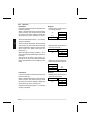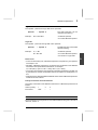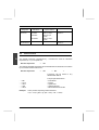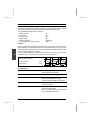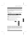
1
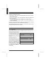
General
A
Grafcet language
B
Ladder language
C
Literal language
D
Operations common to Ladder
and Literal languages
E
Operations on OFB objects
F
and remote I/O objects
Operations in floating point format
Note
Dividers C, D and E only refer to standard PL7-3 objects. Operations on OFB and
remote I/O objects, and PL7-3 language extensions, are described in Divider F.
Floating point format operations, which are specific to regulation, are described
in Divider G.
G
Preface
Compatibility rules
PL7-3 V5 software is used for programming, debugging and preparing the
documentation of V5, V4, V3 or V2 applications.
1 TSX level V2 stations : TSX 67-30/87-10/87-20, execute V2 applications.
2 TSX level V3 stations : TSX 47-30/67-20/87-30, execute V2 or V3 applications.
3 TSX level V4 stations : TSX 47-400/47-410/47-411/47-420/67-410/
67-420/87-410/87-420/107-410/107-420, execute TSX V4 applications.
4 PMX level V4 stations : PMX 47-420/67-420/87-420/107-420/107-430, execute
TSX V4 and PMX V4 applications.
5 TSX level V5 stations : TSX 47-405/47-415/47-425/47-455/67-425/
67-455/87-425/87-455/107-425/107-455, execute TSX V5 applications.
6 PMX level V5 stations : PMX 47-425/47-455/67-425/67-455/87-425/
87-455/107-425/107-455, execute TSX V5 and PMX V5 applications.
7 It is possible to execute an application on a processor of the next level up after
reconfiguration : V2 on V3, V3 on V4 or V4 on V5. This operation is performed
in Local mode and is irreversible. For example an application which is
reconfigured to run on a V5 processor can no longer be run on a lower version
processor.
8 A TSX application can be executed by a PMX processor of the same level. The
converse is also true, as long as the application does not contain any regulation
OFBs or floating point format instructions (level V5).
9 Accessing a V2, V3 or V4 application from PL7-3 V5 provides the user with the
following new services :
• OFB symbolization (V4 application only).
• Search/Replace compatible objects.
• Tables of internal word and constant words used.
• Saving of screens (WRITE/READ), in Data and Debug mode.
1
Compatibility rules (continued)
Principal enhancements of PL7-3 V5 with respect to PL7-3 V4
These new V5 services are only available for V5 applications on V5 stations.
• Inclusion of V5 processors : 18 new processors.
• Configuration mode : transfer of a part of configuration to the station tool
XTEL-CONF (processor, memory, I/O, period of tasks) and slaving of PL7-3 to
XTEL-CONF.
• Inclusion of remote I/O.
• Modularity : view of elementary modules in the PL7-3 application (direct access,
identification and protection) and graphic animation of macro-modules.
• Integration of Literal modules, generated by PL7-PMS2.
• Floating point type operations available with PMX processors. No new floating
point objects.
• New symbols : OFBs, remote I/O and direct connection to XTEL-SDBASE.
• Search/replace mode : extension of replace mode.
• Alt-X function : access to all variables in order to search for cross references.
• Data and debug modes : saving of data screens and program addresses.
• Transfer mode : call up of XTEL-TRANSFER tool for all terminal to PLC and PLC
to terminal transfers.
• Grafcet : management of operating modes using MSIT OFB (define the partition
of the global Grafcet chart, force charts, save/retrieve current situation of a partial
Grafcet chart).
• Document/print mode : table of bits used for internal and constant words.
2
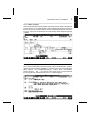
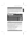
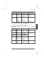
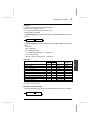
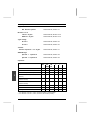
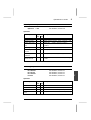
Quick access to Literal language instructions
ACKINT
ADDF
AND
ATB
ATF
Acknowledgment of interrupts....................
Addition in floating point format..................
Logical AND between 2 operands..............
ASCII → binary conversion .......................
ASCII → floating point conversion .............
E, Section 4.1
G,Section 3.1
E, Section 2.7
E, Section 2.8
G,Section 6.3
bit
BTA
BTD
BTF
Testing the direct state of a bit ..................
Binary → ASCII conversion .......................
Binary → BCD conversion .........................
Binary → floating point conversion ............
D, Section 3.4
E, Section 2.8
E, Section 2.8
G,Section 6.1
CALL SRi
CPL
Subroutine call ................... ...................... D, Section 5.4-1
Logical complement of an operand............ E, Section 2.7
DEC
DIVF
DMASKINIT
DOWN
DTB
DTF
Decrement a word .....................................
Division in floating point format ........ .........
Demasking of interrupts ........ ....................
Decrement a counter .................................
BCD → binary conversion .........................
BCD → floating point conversion ......... .....
E, Section 2.2
G,Section 3.4
E, Section 4.1
D, Section 6.3
E, Section 2.8
G,Section 6.5
EQUAL
EQUF
EXCHG
EXEC
Comparison of 2 word tables .....................
Comparison (equal) in floating point format
Transmit and receive a message ..............
Execution of an OFB..................................
E, Section 3.6
G,Section 5.3
D, Section 6.6
E, Section 6.2
FE
FTA
FTB
FTD
Testing the falling edge of a bit ..................
Floating point → ASCII conversion............
Floating point → binary conversion ...........
Floating point → BCD conversion .............
D, Section 3.5
G,Section 6.4
G,Section 6.2
G,Section 6.6
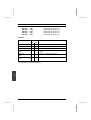
GET
GTB
Retrieval of a word from a register stack ... D, Section 6.4
Gray → binary conversion ......................... E, Section 2.8
HALT
Halt program ............................................. D, Section 5.4-4
IF THEN ELSE
INC
INFF
INPUT
Conditional phrase .....................................
Incrementation of a word ...........................
Comparison (less than) in floating pt format
Reception of a message ............................
JUMP Li
Program jump ............................................ D, Section 5.4-3
MASKINT
MULF
Masking of interrupts ................................. E, Section 4.1
Multiplication in floating point format
G,Section 3.3
NOT or N
Testing the inverse state of a bit ................ D, Section 3.7
OR
OUTPUT
Inclusive OR between 2 words................... E, Section 2.7
Transmission of a message ....................... D, Section 6.6
D, Section 2.6
E, Section 2.2
G,Section 5.2
D, Section 6.6
3
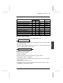
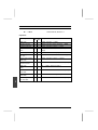
PRESET
PUT
Setting of the preset value ......................... D,Section 6.1/6.3
Storage of a word in a register .................. D,Section 6.4
RE
READBIT
READEXT
READINT
READTLG
READREG
REM
RESET
Testing the rising edge of a bit...................
Immediate reading of discrete input bits.....
Immediate reading of a message...............
Reading of interrupts .................................
Reading of a telegram ...............................
Immediate reading of input registers .........
Remainder of a division..............................
Reset a bit to 0...........................................
Reset a function block to 0 ........................
Return from a subroutine ...........................
D,Section 3.5
E, Section 5.1
D,Section 5.6-1
E, Section 4.1
D,Section 5.7
E, Section 5.2
E, Section 2.5
D,Section 5.2-2
D, Sect.6.3/6.4/6.5/6.6
D,Section 5.4-2
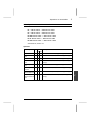
Set a bit to 1 ..............................................
Generation of an interrupt .... .....................
Shift left .....................................................
Shift right ...................................................
Shift left circular ........................................
Shift left circular 1 word .............................
Square root extraction in floating pt format
Square root extraction ...............................
Shift right circular .......................................
Start a function block .................................
Stop a timer ...............................................
Subtract in floating point format .................
Comparison (greater than) in floating point
format .........................................................
D,Section 5.2-2
D,Section 5.5-1
E, Section 2.3
E, Section 2.3
E, Section 2.3
D,Section 5.3-1
G,Section 4
E, Section 2.6
E, Section 2.3
D,Section 6.1/6.2/6.5
D,Section 6.1
G,Section 3.2
RET
SET
SETIT
SHL i
SHR i
SLC i
SLCWORD
SQRTF
SQRT
SRC i
START
STOP
SUBF
SUPF
G,Section 5.1
table+
Summing of words in a table ..................... E, Section 3.5
UP
Increment a counter .................................. D,Section 6.3
WHILE DO
WRITEBIT
WRITEEXT
WRITEREG
Iterative phrase ..........................................
Immediate writing of output bits .................
Immediate writing of a message ..............
Immediate writing of output registers ........
XOR
Exclusive OR between 2 operands............ E, Section 2.7
4
D,Section 2.7
E, Section 5.1
D,Section 5.6-2
E, Section 5.2
Dialogue
5
A
General
Section
1
Divider A
Page
Introduction to PL7-3 software
Contents
1/1
1.1 The multitask concept
1.2 The multilanguage concept
1.3 Symbolic programming
1.4 Modular programming
1.5 I/O configuration files
1.6 Optional function blocks (OFB)
2
Addressable data objects
Contents
2/1
2.1 Addressing
2.2 Bit objects
2.3 Word objects
2.4 Function block objects
2.5 Indexing of data objects
3
User memory
Contents
3/1
3.1 General
3.2 Bit memory
3.3 Word memory
3.4 Memory and application structure
4
Single task software structure
Contents
4/1
4.1 Description of the Master task
4.2 Single task programming
4.3 Single task program execution
A / 1
A
General
Section
5
Multitask software structure
Contents
Page
5/1
5.1 Multitask processing
5.2 Periodic tasks
5.3 Organization of Periodic tasks
5.4 Operating modes of Periodic tasks
6
System bits and words
Contents
6/1
6.1 System Bits
6.2 System Words
6.3 System Bits and Words assigned to remote I/O
7
Power break / return
Contents
7/1
7.1 Principle
7.2 Response to a power return in a single task program
7.3 Response to a power return in a multitask program
8
On-line modification
Contents
8.1 Principle
8.2 On-line modification - PLC stopped
8.3 On-line modification - PLC running
8.4 Restrictions
A / 2
8/1
Dialogue
5
A
Divider A
Section
9
Programming guidelines
Contents
Page
9/1
9.1 Structuring the Periodic tasks
9.2 Structuring the operating modes of the application
9.3 General fault processing
9.4 I/O fault processing
10
Appendices
Contents
10/1
10.1 Optimization of the bit memory
10.2 Compatibility rules TSX and PMX
10.3 Management of PL7-3 language objects associated with TBX modules
A / 3
A
A / 4
Introduction to PL7-3 software
1
A
Introduction to PL7-3 software
Sub-section
1.1 The multitask concept
1.1-1 General
1.1-2 Periodic tasks
1.1-3 Interrupt task
1.2 The multilanguage concept
1.2-1
1.2-2
1.2-3
1.2-4
1.2-5
General
Grafcet language
Ladder language
Literal language
Objects common to the three languages
Section 1
Page
1/2
1/2
1/2
1/3
1/3
1/3
1/4
1/5
1/5
1/6
1.3 Symbolic programming
1/7
1.4 Modular programming
1/10
1.5 I/O configuration files
1/11
1.6 Optional Function Blocks (OFB)
1/12
1.6-1 General
1.6-2 Programming and configuring OFBs
1.6-3 OFBs supplied with PL7-3
This section ends on page
1/12
1/12
1/12
1/13
1/1
A
1.1
The multitask concept
1.1-1 General
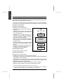
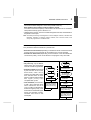
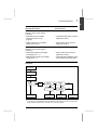
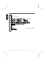
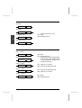
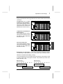
The multitask structure of the model 40 PLCs permits completely independent
programming of the different functions. The control program of each function is
written in an independent module called a "task".
These tasks are executed in parallel by the CPU during the same scan, the priorities
between the different tasks being organized by a "multitask supervisor".
This type of structure offers the following advantages :
• Optimized overall performance and reduced scan time, due to parallel execution
of the various tasks.
• Easier modification and maintenance, since each task can be diagnosed and
modified independently.
The multitask structure offers up to 6 periodic tasks (*) plus one interrupt task. The
type and period of each of the periodic tasks must be declared by the user during
the configuration procedure.
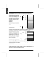
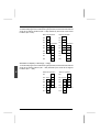
Supervisor
Fast
Task
Master
Task
Auxiliary
Task 0
Auxiliary
Task 1
Positioning
Sequential
Analogue
measurement
Dialogue
+
Priority
–
Example of an application with 4 tasks
1.1-2 Periodic tasks
Each of these tasks is executed cyclically within the period defined by the user
according to the function of the task. The tasks are executed in the following order
of priority (from first to last) :
Fast task → Master task → Auxiliary tasks 0 → 1 → 2 → 3.
The use of the Master task is described in Section 4, and the organization of the
multitask structure in Section 5.
(*)
4 periodic tasks for TSX/PMX 47-40 PLCs
6 periodic tasks for other PLCs (TSX/PMX 67/87/107-40).
1/2
Introduction to PL7-3 software
1
A
1.1-3 Interrupt task
The execution of this task is not cyclical or periodic, but is initiated by an interrupt
call from one of the intelligent I/O modules (e.g. a TSX DTM 100 module). The
interrupt task has priority over all other tasks and the routines performed by this task
must be kept short to avoid disturbing the execution of the other tasks.
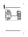
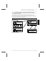
1.2
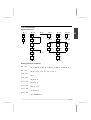
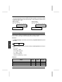
The multilanguage concept
1.2-1 General
In an ideal system, each function (sequential processing, analog measurement and
regulation, communication, etc.) could be programmed in the language best suited
to its specific character.
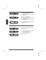
This is exactly what is offered by the PL7-3 software of TSX/PMX 47/67/87/107-40
PLCs, which offers 3 different programming languages that can be used on their
own or mixed in the same program, so that each function, subroutine or program
module can be written in the most suitable programming language.
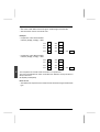
Interrupt Task
Fast Task
Master Task
Auxiliary Tasks
Subroutines
Subroutines
Subroutines
Subroutines
• Ladder or
• Literal
• Ladder or
• Literal
• Ladder or
• Literal
• Ladder or
• Literal
Main
Program
Main
Program
Main
Program
Main
Program
• Ladder or
• Literal
• Ladder or
• Literal
• Ladder or
• Grafcet or
• Literal
• Ladder or
• Literal
1/3
A
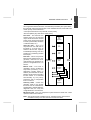
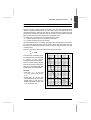
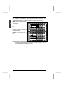
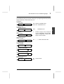
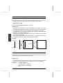
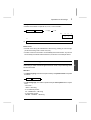
1.2-2 Grafcet language
This is the ideal graphic language for describing the sequential functions of an
automated system, from a macro-step down to a single bit. The actions associated
with the steps and the conditions associated with the transitions can be written in
either Ladder or Literal language.
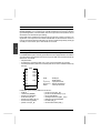
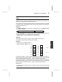
Macro-representation and macro-steps
PL7-3 Grafcet language permits
the macro-representation of a
control system through the use of
macro-steps. A macro-step is a
single Grafcet symbol which can
describe a complete sequence or
functional sub-assembly of the
control system (e.g. Weighing,
Mixing, Filling, Packing, etc.). This
feature enables a complete control
system, broken down into its main
functional sub-assemblies, to be
displayed on a single screen of
the terminal.
When a macro-step is activated,
the sequence that it represents
(known as the macro-step
expansion) is executed. The
expansion may also contain one
or more macro-steps.
IN
1
1
11
M1
2
12
2
3
13
OUT
By positioning the cursor on the macro-step and pressing the Zoom key, the
expansion of the macro-step can be read, written or modified as required.
1/4
Introduction to PL7-3 software
1
A
1.2-3 Ladder language
This is the familiar relay logic language that is widely used for simple combinational
logic processing. PL7-3 Ladder language, with its extensive range of preprogrammed
function blocks and operation blocks, and its sophisticated Window and Zoom
functions, is the most comprehensive and user-friendly Ladder Diagram language
available.
1.2.4 Literal language
This is a high-level English statement language, with powerful arithmetic, operator
dialogue and data handling capabilities. It is written in the form of action phrases
(SET ... RESET ... etc.), conditional phrases (IF ... THEN ... ELSE ...) and iterative
phrases (WHILE ... DO ...), and has the same wide range of preprogrammed
function blocks and operation blocks as PL7-3 Ladder language.
1/5
A
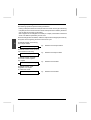
1.2-5 Objects common to the three languages
• Object bits, including I/O bits, internal bits and system bits.
• Word objects, composed of 16 or 32 bits, which are used to store values and to
exchange data with the intelligent modules. The bits in these words are also
addressable data objects (called "bits extracted from words") and can therefore be
used in the program.
• Function blocks, incorporating preprogrammed functions such as timers, counters,
monostables, registers, text blocks, etc., which are controlled by bits and words.
These data objects are accessible only in the Ladder and Literal languages.
However, the actions and conditions associated with Grafcet steps and transitions
are written in either Ladder or Literal language. Grafcet language also contains a
small number of bit objects and words (e.g. Xi, Xi,V) that are specific to this
language.
Example :
1/6
Introduction to PL7-3 software
1
A
1.3
Symbolic programming
PL7-3 language allows the user to enter and display data objects either by their
addresses (example : B1), or by a character string called a symbol (example :
Pump 1). Before writing all or part of a program that uses symbolic programming,
all of the symbols used must be entered in a mnemonic symbol database with their
corresponding PL7-3 language objects.
This mnemonic symbol database, which is managed by the XTEL-SDBASE tool,
applies to the whole station. It has the advantage that all the station's symbols are
defined once only and made available for all the Software Workshop functions or
tools.
PL7-3 reads each symbol directly in the XTEL-SDBASE in order to display it (the
idea of a local database no longer exists). This means, amongst other things, that
there is no longer a limit of 5000 symbols.
OFB symbolization
Each OFB comprises several levels of representation :
•
•
•
•
The OFB type : for example MVDGS.
The OFB itself : for example MVDGS1.
The OFB element : for example MVDGS1,STATUS.
The extract bit of an OFB element : for example MVDGS1,STATUS,5.
PL7-3 symbolic programming has 3 OFB symbolization levels, so that the programmer
can select the one which is best suited to his program :
• The OFB : for example Valve.
• The OFB element : for example Valvesta.
• The extract bit of an OFB element : for example Valmach.
PL7-3 does not allow the OFB type to be symbolized, on the other hand it does allow
the symbolization of indexed forms of objects.
The bits are extracts of word objects but not double word objects.
Example
Symbol
Marker
Symbolic syntax
Marker syntax
Valve
MVDGS1
Valve,STATUS
Valve,STATUS,5
EXEC Valve(..=>..)
MVDGS1,STATUS word
MVDGS1,STATUS,5
EXEC MVDGS1bit (..=>..)
Valvesta MVDGS1,STATUS
Valvesta
Valvesta,5
MVDGS1,STATUS word
MVDGS1,STATUS,5 bit
Valmach MVDGS1,STATUS,5
Valmach
MVDGS1,STATUS,5 bit
1/7
A
Distributed I/O symbolization
Each remote I/O comprises several levels of representation :
•
•
•
•
The device : for example RAO3.
The module : for example RAO3,1.
The channel : for example RAO3,1,3.
The channel bit extract : for example RAO3,1,3,F.
PL7-3 symbolic programming has 3 distributed I/O symbolization levels, so that the
programmer is able to select the one which is best suited to his program :
• The module : for example Motor.
• The channel : for example Norevs.
• The channel extract bit : for example Dirrot.
PL7-3 does not allow the type of device to be symbolized, on the other hand it does
allow the symbolization of indexed forms of objects.
The bits are extracts of objects of word and not double word type.
Example
Symbol
Marker
Symbolic syntax
Marker syntax
Motor
RAO3,1
Motor,3
Motor,3,F
RAO3,1,3 word
RAO3,1,3,F bit
Norevs
RAO3,1,3
Norevs
Norevs,F
RAO3,1,3 word
RAO3,1,3,F bit
Dirrot
RAO3,1,3,F
Dirrot
RAO3,1,3,F bit
The following phrases can thus coexist in the same PL7-3 application :
< Speed greater than 1200 revs per minute ?
!
IF [Norevs > 1200] THEN ...
< But in which direction is the motor rotating ?
!
IF [Dirrot = 1] THEN ....
(and not Norevs,F)
The indexed forms can apply to the channel or the channel extract bit, but not both at
the same time :
RAO3,1,3(W20),F or RAO3,1,3,F(W40).
Note
This example at four levels of symbolization does not apply to TBX discrete modules.
1/8
1
Introduction to PL7-3 software
A
Rules for use of symbols by PL7-3
If the mnemonic symbol database contains several levels of symbolization for
the same object, PL7-3 always looks for the symbolic form of objects, and
starts with the object with the most complex syntax.
Examples
• Valve and Valmach are present in the mnemonic symbol database.
• When the application program is entered, one phrase contains Valve, STATUS,5.
• When the program in read in the PLC, it is Valmach and not Valve,STATUS,5
which is found.
• Norevs and Dirrot are present in the mnemonic symbol database.
• When the application program is entered, one phrase contains Norevs,F.
• When the program is read in the PLC, it is Dirrot and not Norevs,F, which is found.
1/9
A
1.4
Modular programming
Modular programming is performed in several phases :
• Source archiving under PL7-3, of program modules (main chart, preliminary,
macro-step, main program, subroutine,etc), constant words, OFB constants and
entry of module comments.
• Generation under XTEL-MOD, starting from the source files previously created
using PL7-3, of elementary modules and macro-modules (set of elementary
modules). The symbols file, associated with an elementary module, is not
provided by PL7-3 but generated by XTEL-MOD by reading the XTEL-SDBASE
mnemonic symbol database.
• Retrieval of elementary modules and/or macro-modules, created using XTEL-MOD
and their integration into a PL7-3 application. PL7-3 offers the following functions
for ease of updating the application :
-
direct access to the code of the elementary module
marking the code of the elementary module
protecting the code of the elementary module
graphic view and animation of macro-modules (or functional modules).
Note
Elementary modules and macro-modules can also be created from source files, generated
using PL7-PMS2 process control language. Thus it is possible for PL7-3 to automatically
integrate the code generated by PL7-PMS2.
1/10
Introduction to PL7-3 software
1
A
1.5
I/O configuration files
When used in Local mode, certain software tools such as PL7-COM, PL7-PCL,
PL7-AXE and PL7-NET need to know the I/O configuration of the application.
When PL7-3 is used with a V4 station it generates an ASCII file (.IOC extension)
containing the I/O configuration, whose purpose is :
• To permit the copying of a standard I/O configuration from one station to another.
• To act as an interchange file with the dedicated functions when they are used in
Local mode.
• To allow XTEL to support file exchange with computer aided design of a library
of electrical diagrams : the .IOC file is used for the generation of the neutral I/O
file describing the tree structure of a PLC configuration).
X-TEL
Station p
Station n
PL7-3
PL7-NET
PL7-PCL
PL7-COM
PL7-AXE
PL7-3
TRANSFER
▲
▲
▲
▲
▲
▲
.IOC file
CAD of a library
of electrical
diagrams
1/11
A
1.6
Optional Function Blocks (OFB)
1.6-1 General
Optional Function Blocks (OFBs) are not part of the standard PL7-3 language
package. They are an extension of PL7-3, supplied separately on diskette.
Each OFB is written in a computer programming language by its designer and is
identified by its type and number. Each OFB belongs to a single family, i.e. axis
control, communication. Within a family of OFBs, there can be a variety of different
types of OFB.
A type of OFB can be used a number of times in the same application program, as
long as the :
• Type of OFB is loaded in the memory.
• Number of OFBs to be used is defined in the configuration.
Each OFB that is used has its own I/O parameters, internal data and constants that
can be accessed with PL7-3.
1.6-2 Programming and configuring OFBs
Before using OFBs in an application, their number must be defined in the configuration.
This ensures :
• Reservation of the memory field required by each OFB.
• Initialization of OFB internal constants.
The use of an OFB in an application program enables :
• Running the program conditionally based on I/O parameters.
• Reading internal data or constants.
• Assignment of internal data.
1.6-3 OFBs supplied with PL7-3
Application diagnostics OFBs (EVDGNi, EVDGSi, MVDGNi, MVDGSi, TRDGNi and
TRDGSi) enable process monitoring to be set up :
•
•
•
•
•
Monitoring of equations.
Monitoring of Grafcet evolutions (steps and macro-steps).
Monitoring of Grafcet time out.
Monitoring of the reaction time of the process to a command.
Monitoring of safety conditions, etc.
The Grafcet OFB (MSITi) manages partial Grafcet situations :
•
•
•
•
Clear definition of partial Grafcet descriptor.
Forcing of partial Grafcet.
Saving and restoring the current situation.
Positioning a situation.
1/12
Addressable data objects
2
A
Addressable data objects
Sub-Section
2.1 Addressing
2.1-1
2.1-2
2.1-3
2.1-4
Discrete rack-mounted I/O
Input and output register words
Remote discrete I/O
Symbolic addressing
2.2 Bit objects
2.2-1 List of bit objects
2.2-2 Definition of the main bit objects
2.3 Word objects
2.3-1 General
2.3-2 List of word objects and associated bits
2.3-3 Definition of the various word objects
2.4 Function Block Objects
2.4-1 General
2.4-2 List of function block words and bits
2.5 Indexing of data objects
2.5-1 Direct addressing
2.5-2 Indexed addressing
This section ends on page
Section 2
Page
2/2
2/2
2/3
2/4
2/5
2/6
2/6
2/7
2/8
2/8
2/9
2/10
2/11
2/11
2/12
2/13
2/13
2/13
2/14
2/1
A
2.1
Addressing
2.1-1 Discrete rack-mounted I/O
The discrete rack-mounted I/O modules can have 4, 8, 16, 24 or 32 I/O points. The
address of an input or output is defined by :
• For 4, 8 and 16 point I/O modules
I/Oxy,i
I :
O:
x :
y :
, :
i :
• For 24 and 32 point I/O modules
I/Oxy,i (for points 0 to 15)
I/O(x+1)y,i (for points 16 to 23 or 31)
input
output
number of rack containing the module
number of slot in the rack (0 to 7)
comma
number of the I/O point.
Definition of the rack number
• For TSX/PMX 47-40/67-40/87-40/107-40 PLCs
0 1 2 3 4 5 6 7
X
D
S
T
3
2
Module
I/O
Addresses
4
point
8
point
16
point
24
point
32
point
0y,0
to
0y,3
0y,0
to
0y,7
0y,0
to
0y,F
0y,0
to
0y,F
0y,0
to
0y,F
1y,0
to
1y,7
1y,0
to
1y,F
2y,0
to
2y,F
2y,0
to
2y,F
3y,0
to
3y,7
3y,0
to
3y,F
x = 0/1
I/O
Addresses
x = 2/3
2/2
2y,0
to
2y,3
2y,0
to
2y,7
2y,0
to
2y,F
2
Addressable data objects
A
• Extensions for TSX/PMX 47-40/67-40/ 87- 40 PLCs
0 1 2 3 4 5 6 7
X
D
S
T
3
2
Modules
4
point
8
point
16
point
I/O
xy,0
to
xy,3
xy,0
to
xy,7
xy,0
to
xy,F
addresses
24
point
xy,0
to
xy,F
32
point
xy,0
to
xy,F
(x+1)y,0 (x+1)y,0
to
to
(x+1)y,7 (x+1)y,F
x
I/O
addresses
(x+1)y,0
(x+1)y,0
to
to
(x+1)y,0
to
(x+1)y,3
(x+1)y,7
(x+1)y,F
x+1
TSX 47-410/411/420
TSX 47-415/425/455
PMX 47-420/425/455
X = 4, 6
X+1 = 5, 7
TSX 67-40/87-40/107-40
PMX 67-40/87-40/107-40
X = 4, 6, 8, A, C, E
X+1 = 5, 7, 9, B, D, F
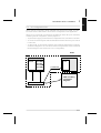
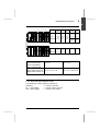
2.1-2 Input and output register words
The addressing of these registers is defined by :
IW/OWxy,i
IW : input register
OW : output register
x : number of the rack
y : number of slot in the rack
i : number of the register
2/3
A
2.1-3 Remote discrete I/O
Remote I/O modules have a modular construction with 16 or 32 channels per
connection point on the FIPIO bus : 16 channels for a "monobloc" TBX and 32
channels for a modular TBX. The remote I/O address is defined by : RI/ROx,y,i
RI
RO
x
,
y
,
i
: remote input
: remote output
: number of connection point on FIPIO bus (1 to 62)
: comma
: module number : 0 for the base and 1 for the extension
: comma
: point number (0 to 15).
Defining the device address
Micro-switches on the devices enable binary coding of the address (or connection
point) within the following limits :
No of FIPIO
No of TBX
connection points addresses managed
PLC type
___________________________________________________________________________________________________
TSX 47 415
TSX/PMX 47 455
32
31 (1 to 62)
___________________________________________________________________________________________________
TSX/PMX 67 455/87 455/107 455 64
62 (1 to 62)
___________________________________________________________________________________________________
Note
Addresses 0 and 63 are reserved for the PLC and the terminal respectively.
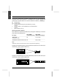
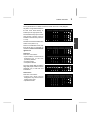
Example of the addressing of a monobloc TBX device (maximum of 31 devices per
architecture) : device code at address 15.
0 0 0 0
0
16 8 4 2
1
Example of the addressing of a modular TBX device (maximum of 62 devices per
architecture) : device code at address 62.
0 0 0 0
2/4
0 0
0 0
128 64 32 16 8 4
2 1
Addressable data objects
2
A
2.1-4 Symbolic addressing
The symbolic addressing of PL7-3 objects requires the symbols used to have
already been defined in the mnemonic symbol database.
Symbol
A symbol is a string of eight alphanumeric characters where the first character must
be alphabetical. The “_”, “$”, “%”, “|” and “-” characters are also accepted. A symbol
cannot have the same syntax as a PL7-3 language element. The first letter of a
symbol name is always in capitals.
Symbolized objects
All PL7-3 objects can be replaced by a symbol, except :
• Indexed bits and words
• Badges
• Subroutines
• Bit and word tables.
There are three types of objects that can be represented by symbols :
• Simple type objects : an object that can be assigned a mnemonic symbol.
Examples :
Function block
Module
Internal bit
Internal word
Internal word bit
System word bit
TXT1
I2
B1
W1
W1,1
SW2,3
Text1
Modi2
Bit1
Wordw1
Bitw1_1
Bit3_sw2
• Complex type objects : an object that can be split into sub-objects without the subobject appearing in the table of symbols.
Examples :
I/O bit
Internal word bit
Function block bit
I2,1
W1,3
TXT1,E
Modi2.1
Wordw1,3
Text1,E
Symbols cannot be applied to :
- A step bit : If X1 is symbolized by Step1, X1,2 cannot be symbolized by Step1,2
as Step1 symbolizes the enable bit for step 1 in the chart while in X1,2, X1
represents macro-step 1.
- A step word : If X1,2 is symbolized by Bitx12, X1,2,V cannot be symbolized by
Bitx12,V as Bitx12 symbolizes the enable bit for step 2 of macro-step 1, while in
X1,2,V, X1,2 represents step 2 of macro-step 1.
• Compound type object : an object that comprises more than one object.
Examples :
Indexed internal bit
B1(W1)
Temp_ok(Ad_emis0),
Internal word bit
W1(W1),1 Ad_emis0(ad_emis0),1
Note : For bit extracts of words : internal word bits, constant word bits, OFB word
extracts etc, where it exists the mnemonic symbol for the object having the
most complicated syntax is used : the mnemonic symbol associated with
the word bit and not that associated with the word.
2/5
A
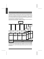
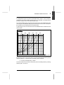
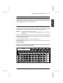
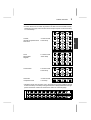
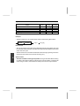
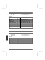
2.2
Bit objects
2.2-1 List of bit objects
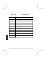
The abbreviations used in the right-hand column are : R for reading, W for writing,
F for forcing.
Bits
Type
Addressing
Possibilities
direct
indexed
limit
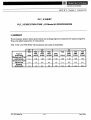
Ixy,i
Ixy,i(Wj)
0≤i≤F
R/W/F
Rack-mounted
discrete I/O
module bits
inputs
outputs
Oxy,i
Oxy,i(Wj)
0≤i≤F
R/W/F
Discrete
remote I/O
module bits
inputs
RIx,y,i
RIx,y,i(Wj)
0≤i≤15
R
outputs
ROx,y,i
ROx,y,i(Wj)
0≤i≤15
R/W/F
Intelligent
module
bits
inputs
Ixy,i
Ixy,i(Wj)
0≤i≤F
R/W
outputs
Oxy,i
Oxy,i(Wj)
0≤i≤7
R/W
Internal bits
Bi
Bi(Wx)
0≤i≤3935
R/W/F
System bits
SYi
0≤i≤127
R all, W some
Grafcet
bits
step i of the
main chart
Xi
R/W
0≤i≤127
0≤j≤63
macro-step j
XMj
R
step i of
macro-step j
Xj,i
R/W
IN step of
macro-step j
Xj,I
R/W
OUT step of
macro-step j
Xj,O
R
Default bit of
I/Oxy,S
rack-mounted discrete & intelligent modules
Default bits of
channel fault
remote discrete
modules
break in
0≤i≤15
output channel
reset output
channel
R
RDx,y,i
R
TRIPx,y,i
R
RSTx,y,i
R/W
Notes
Reading/writing : the bit objects can be read or written by the user program or by
the terminal.
Forcing of I/O and internal bits : A bit that has been forced retains its forced state until
it is unforced by the terminal, irrespective of the logic states that would normally be
induced by the user program.
2/6
2
Addressable data objects
A
2.2-2 Definition of the main bit objects
I/O bits
These bits indicate the states of the inputs and outputs of the I/O modules.
Indexing :
Indexing can be applied to all I/O and internal bits.
Example : O5,9 (W6)
The incrementation of word W6 enables all the output bits
of the I/O modules in the configuration to be addressed
from O5,9 onwards.
Note :It is important to remember during indexed addressing that the bit memory is a
continuous memory zone and does not take account of any empty spaces in the I/O
configuration, whether these "spaces" are caused by mixing 4, 8 and 16 point modules
in the configuration, or whether they are caused by leaving empty slots in the rack (see
Appendix page 9/10).
I/O module fault bits
Each module has an addressable fault status bit which is set to 1 by the system when
a fault occurs. For example :
• The physical configuration of the module does not conform to the software
configuration declared during the configuration procedure.
• The I/O exchange with the processor is not valid.
• The terminal block of the module is disconnected.
• Overvoltage on one of the points of an 8-point output module, etc.
Special case of 4-point rack-mounted I/O and distributed I/O modules
The TSX DET 466 and TSX DET 417 4-point module as well as distributed discrete
I/O modules have one fault bit per I/O point :
• 4-point modules : bit 4 -> point 0, 5 -> point 1, 6 -> point 2 and 7 -> point 4.
Example : I41,5
Fault bit of point 1 of the output module located in slot 1 of
rack 4.
• Remote I/O modules : RDx,y,i with i point number.
Example : RD4,1,5
Fault bit of point 5 of the extension module connected to
address 4 on the FIPIO bus.
Internal bits
Internal bits are used to store logic states during the execution of the program.
Note :I/O bits that are not used cannot be used as internal bits.
System bits
System bits SY0 to SY127 enable the user to monitor the operation of the PLC and
the application program. The use of these bits is described in Section 6.
2/7
A
2.3
Word objects
2.3-1 General
Addressable word objects can have two different formats :
• Single length words of 16 bits, which are stored in the data memory zone and
which can contain an algebraic value of -32 768 to +32 767.
• Double length words of 32 bits, which can contain an algebraic value of -2 147
483 648 to +2 147 483 647. These words are stored in the data memory zone as
two consecutive single length words.
Immediate values
These are algebraic values of the same format as the single and double length
words (16 or 32 bits) and which permit values to be assigned to the data words.
These values are stored in the program memory zone and can represent single
length values of -32 768 to +32 767 or double length values of -2 147 483 648 to
+2 147 483 648, and +3,402824 E + 38 and +1.175494 E-38 in floating point format
(double length).
Word formats
The contents of the words or immediate values are stored in the user memory in
binary code with the following convention :
16-bit word
F E DC B A 9 8
7 6 5 4
3 2 1 0
0 1 1 1
0 0 1 1
0 1 0 0
0 1 1 1
^
MSB
32-bit word
^
LSB
1 0 1 0
0
Bit number
0 0 1 0
MSB
LSB
0 0 1 1
Word n
1 0 1 0
Word n+1
Single length words and immediate values can be entered and displayed on the
terminal screen in the following notations :
• Decimal
1579
maximum 32767
minimum -32768
• BCD
B'1439'
maximum B'9999'
minimum B'0000'
• Binary
L'0101001100011010'
• Message (ASCII)
• Hexadecimal
H'A536'
maximum H'FFFF'
minimum H'0000'
M'JM'
Double length words and immediate values can be entered and displayed on the
terminal screen in decimal or floating point notation only.
2/8
2
Addressable data objects
A
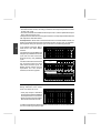
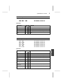
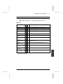
2.3-2 List of word objects and associated bits
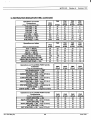
The abbreviations used are : R for reading and W for writing
Words
Internal words
Type
Addressing
direct
indexed
single length
Wi
Wi(Wj)
0≤i≤32596
R/W
double length
DWi
DWi(Wj)
0≤i≤32595
R/W
CWi
CWi(Wj)
0≤i≤26206
R/W (1)
CDWi
CDWi(Wj)
0≤i≤26205
R/W (1)
Constant words single length
double length
Register words
input words
IWxy,i
0≤i≤7
R/W
output words
OWxy,i
0≤i≤7
R/W
Common words common word j
of station i
System words
COMi,j X = B, C, or D
or COMXi,j
SWi
R/W (2)
0≤i≤n
0≤j≤m
0≤i≤127
Grafcet
words
step i of
main chart
Xi,V
Xj,i,V
0≤i≤127
step i of
macro-step j
IN step
of macro-step j
Xj,I,V
OUT step
of macro-step j
Xj,O,V
0≤j≤63
Possibilities
limits
(4)
(4)
R/W
R
Status word associated
with remote discrete I/O modules
R
R
R
STS,x,y,i
0≤i≤15
Bits extracted
from single
bit j of
internal word i
Wi,j
Wi(Wk),j
0≤j≤F
length words
bit j of
constant word i
CWi,j
CWi(Wk),j
0≤j≤F
bit j of
register word i
I/OWxy,i,j
bit k of common
word j of
station i
bit j of
system word i
0≤j≤F
COMi,j,k
or COMXi,j,k
R
R/W (3)
R
R/W (3)
R/W (2)
0≤k≤F
SWi,j
0≤j≤F
R/W
Notes : Reading/writing : by the program or by the terminal :
(1)
(2)
writing only possible by the terminal,
writing only possibly by program of station i,
Number of stations
33 to 64
17 to 32
9 to 16
5 to 8
2 to 4
COM word size
4
8
16
32
64
(3)
(4)
writing only possible by the program,
refer to the table below :
Station no : i
0 to 63
0 to 31
0 to 15
0 to 7
0 to 3
Word no : j
0 to 3
0 to 7
0 to 15
0 to 31
0 to 63
2/9
A
2.3-3 Definition of the various word objects
Internal words : used to store values during the execution of the program.
Single and double length internal
words are stored in the same data
memory zone. Double length word
DWn therefore corresponds to
single length words Wn and Wn+1
(word Wn storing the LSB and
word Wn+1 storing the MSB of
word DWn).
DW0
DW1
DW3
DW2
W0
W1
W2
W3
W4
Examples :
DW0 corresponds to W0 and W1,
DW543 corresponds to W543 and
W544.
Wi
DWi
Wi + 1
Constant words :
Constant words are used to store constant (invariable) values, or alphanumeric
messages. The contents of these words can only be written or modified by the
terminal. They can be stored in EPROM and are identified as follows :
Single and double length constant
words are stored in the same
memory zone. Double length word CDW1
CDWn therefore corresponds to
single length words CWn and
CWn+1 (word CWn storing the
LSB and word CWn+1 storing the
MSB of word CDWn).
CDWi
CDW0
CW0
CW1
CW2
CWi
CWi + 1
Input and output register words
Input and output register words are 16-bit word objects that are associated with
intelligent I/O modules. Each intelligent module has 8 input register words (IWxy,i)
and 8 output register words (OWxy,i).
Common words
Common words are 16-bit words that are common to all the stations on a
MAPWAY,TELWAY, ETHWAY or FIPWAY network. In each PLC, they constitute
a table of 64 words for a TELWAY network, 128 words for a FIPWAY network, or
256 words for a MAPWAY or ETHWAY network.
2/10
Addressable data objects
2
A
System words
These are 16-bit words that can be used to monitor the operation of the system and,
in certain cases, to modify the execution of the application program.
System words are described in Section 6.2.
Grafcet words
These words represent the active time value of a Grafcet step. Their maximum value
is 9999 increments of the time base, which is 100 ms. The number of active time
words required is declared during the configuration procedure, irrespective of the
number Grafcet steps.
Bits extracted from single length words
The PL7-3 software can also address any of the 16 bits in a single length word. The
address is formed by simply adding the number of the bit to the address of the
corresponding word.
2.4
Function block objects
2.4-1 General
Function blocks can be used in Ladder or Literal language. They can also be used
in the Preprocessing and Post-processing section of a Grafcet program, since these
sections are also written in Ladder or Literal language. There are three types of
function blocks :
• Standard function blocks, which provide pre-programmed functions such as
timers, counters, monostables and registers.
• Text function blocks, which permit the exchange of data, either locally or through
a TELWAY, MAPWAY, ETHWAY or FIPWAY network, between the user program
and :
- an intelligent I/O module
- the terminal port of the PLC (for communication with peripherals)
- another user program (in a PLC on a network)
- the system (for diagnostics).
• Control function blocks, which are used in multitask programs to activate and
deactivate the various periodic tasks (Fast task, Auxiliary tasks).
The other types of blocks (i.e. comparison blocks and operation blocks) also use the
bits and words defined in this section.
• Optional Function Blocks (OFBs), which are an extension of PL7-3 providing
specific functions (communication, axis control, etc.).
2/11
A
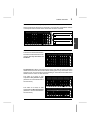
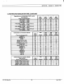
2.4-2 List of standard function block words and bits
Standard function blocks use the following specific words and output bits. The
abbreviations used in the right-hand column are : R for reading and W for writing.
Function blocks
Associated words and bits
Addresses
Possibilities
Timer
Ti
0≤i≤127
words preset value
current value
Ti,P
Ti,V
R/W
R
bits
timer running
timer done
Ti,R
Ti,D
R
R
words preset value
current value
Mi,P
Mi,V
R/W
R
bits
Mi,R
R
words preset value
current value
Ci,P
Ci,V
R/W
R
bits
Ci,E
Ci,D
Ci,F
R
R
R
words input word
output word
Ri,I
Ri,O
R/W
R/W
bits
Ri,F
Ri,E
R
R
TXTi,L
TXTi,S
TXTi,M
W
R
W
TXTi,C
TXTi,A
W
W
TXTi,T
W
TXTi,V
R
TXTi,D
TXTi,E
R
R
CTRLi,R
R
Monostable
Mi
0≤i≤31
Counter
Ci
0≤i≤255
Register
Ri
0≤i≤127
Text block
TXTi
0≤i≤63
monostable running
counter empty
counter done
counter full
register empty
register full
words length of table in bytes
status word
module address and
channel number
request code
TELWAY network
station address
corresponding
text block number
exchange confirm
bits
exchange done
exchange confirm
Control block
bit
task activated
CTRLi
1≤i≤7 except 3 (Master task)
(1)
(1)
(1)
These bits and words cannot be indexed.
(1)
If modification (YES) was authorized during the configuration procedure.
2/12
Addressable data objects
2
A
2.5
Indexing of data objects
2.5-1 Direct addressing
In direct addressing, the address of a data object is defined by a specific number
that represents the storage location of the data object in the user memory.
Example : B126 designates the internal bit with the memory location 126.
2.5-2 Indexed addressing
In indexed addressing, the address is defined by the memory location number plus
an index. The index is defined by the contents of a single length word Wi, which can
be a positive or negative value. The number of "index words" that can be used is
unlimited.
Example W108(W2) : Data word address 108 + the contents of word W2. If word
W2 contains the value 45, the indexed address W108(W2)
is equivalent to the memory location W153, since
108+45 = 153.
The advantage of an indexed address is that it enables a whole string of data objects
of the same type to be addressed, simply by modifying the value of the index word.
Example B80(W4)
: If the value of word W4 is incremented by program from 0
to 20, the indexed address B80(W4) designates in
succession the internal bits B80 to B100.
The list of bit objects and word objects that can be indexed is given in Sections 2.2-2
and 2.3-2.
Index overflow - system bit SY20
The index is said to "overflow" when the address of the indexed object exceeds the
limits of the memory zone assigned to the type of object concerned, that is to say
when :
• The base address plus the value of the index word is less than zero.
• The base address plus the value of the index word is greater than the number of
data objects declared during the configuration of the application (e.g. 1000 W
internal words).
In the case of an index overflow, the system automatically :
• Sets system bit SY20 to 1.
• Resets the value of the index to zero.
If indexed addressing is used, system bit SY20 must be monitored by the program
so that an index overflow can be corrected. After the overflow has been corrected,
the system bit SY20 must be reset to 0.
System bit SY20 : • Initial state 0.
• Set to 1 by the system (index overflow fault).
• Reset to 0 by the program (fault acknowledgement).
2/13
A
2/14
User memory
3
A
User Memory
Section 3
Sub-section
Page
3.1 General
3/2
3.2 Bit memory
3/2
3.2-1 Composition
3.2-2 Structure
3.3 Word memory
3.3-1
3.3-2
3.3-3
3.3-4
Program zone
Constants zone
Data zone
Program identifier (IDP)
3.4 Memory and application structure
3.4-1
3.4-2
3.4-3
3.4-4
TSX and PMX 47-40 PLC
TSX and PMX 67-40 PLC
TSX/PMX 87-40 and TSX/PMX 107-40 PLC
Memory configuration rules
This section ends on page
3/2
3/3
3/4
3/4
3/5
3/5
3/6
3/7
3/7
3/8
3/9
3/10
3/10
3/1
A
3.1
General
In TSX/PMX 47/67/87/107-40 PLCs, the memory space accessible to the user is
divided into two separate memories :
• The bit memory, which is an on-board CMOS RAM memory that can store the
image of 4096 bit objects.
• The 16-bit word memory, which stores the program, data and constants, and
which is composed of :
- An on-board CMOS RAM memory integrated in the processor module
- The RAM or EPROM user memory cartridges, which can have a capacity of 32,
64, 128 or 256 Kwords.
These two memories (the bit memory and the word memory) must be configured
according to the type of PLC used, as described in Section 3.4.
All the CMOS RAM memories are backed up by nickel-cadmium batteries which
protect the contents after power is removed.
3.2
Bit memory
3.2-1 Composition
The bit memory can store a maximum of 4096 bits, irrespective of the type of PLC.
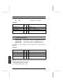
The size of the first two zones of
the bit memory (System reserve
and System bits) is fixed. The size
of the other four zones is defined
by the configuration declared by
the user.
The structure of the bit memory is
described in Section 3.4.
After configuring the number of bit
objects required for the application,
there may be some unused bits
left over. It is advisable not to
declare all of these as internal
bits, but to leave them in reserve
for possible future extensions to
the number of I/O modules or
Grafcet steps.
3/2
Reserved for system
System bits
SYi
Rack-mounted remote I/O bits I/Oxy
Grafcet step bits
Grafcet macro-step bits
Internal bits
Remote I/O bits
OFB object bits
Xi
XMi
Bi
RI/ROx,y
3
User memory
A
3.2-2 Structure
The state of each bit object in the bit memory is recorded on 3 bits as follows :
Reserved
F
A
C
Current state (only bit accessible
by PL7-3)
Previous state
Forced state
During the updating of the bit memory, the system ensures :
• The transfer of the image of the current state into the previous state.
• The updating of the current state by the program, the system or the terminal (when
a bit is forced).
Rising or falling edge operations
This structure of the bit memory allows a test to be made for a rising edge or a falling
edge on :
• The I/O bits (except the I/O fault bit S).
• The internal bits.
Rules of use for edge operations
• For input bits, the edge contact must be processed in the task in which the input
module is exchanged.
• For output bits or internal bits, the reading and writing of an edge must be
processed in the same task.
• In Ladder language, the output coil associated with an edge contact must be
written only once in the program.
Forced states
On receipt of a forcing request from the terminal :
• The forced state F is set to 1.
F=1
• The current state C is set to 1 if forcing to 1 was requested C = 1
The current state C is set to 0 if forcing to 0 was requested C = 0
• The previous state is frozen at its value at the moment of forcing.
These states are frozen until :
• Forcing is cancelled (unforced) and the bit concerned is updated.
• Inverse forcing is requested, when only the current state is modified.
3/3
A
3.3
Word memory
The word memory (of 16-bit words) is divided into four logical zones :
• The program, data and constants
zones, whose sizes are defined
Application Data
by the user during the
configuration
procedure
OFB Data
according to the requirements of
the application.
Application Program
• The program identifier zone.
The first three zones each
comprise a standard part assigned
to the application and a part
assigned to the OFBs.
All of these logical zones are
distributed over the two available
physical spaces (see Section 3.4) :
• On-board RAM, depending on
the PLC selected, and
• Memory cartridge (one cartridge
only).
OFB Program
Application Constants
OFB Constants
IDP
3.3-1 Program zone
The program zone is divided into the following segments :
• The executable code segment
UCSi, which includes :
- the Grafcet interpreter (if
Grafcet is declared in the
configuration),
- the interpretive code of the
PL7-3 instructions.
• The non-executable code
segment UGSi, which includes :
- the graphic elements of the
PL7-3 instructions,
- the comments.
• The common parameter
segment CPS, which includes :
- the configuration parameters,
- the links between the
executable code elements and
the non-executable code
elements.
3/4
Executable
Grafcet Interpreter
if Grafcet is declared
code
Segment (s)
UCS
User program
PL7-3 interpretive code
Nonexecutable
code
Segment (s)
UGS
User program
• graphics, contact networks,
phrases, pages
• comments
Segment
CPS
Configuration parameters
depending on the application
Segment (s)
OES
Executable
code
OFB
interpretive code
Segment (s)
OPS
OFB
Configuration parameters
User memory
3
A
• The OFB executable code segment OESi, which includes :
- the OFB order number,
- the initial constants sections.
• The OFB configuration parameter segment OPSi.
The program zone can contain several UCSi and UGSi segments, depending on the
structure of the application (single task or multitask, with or without Grafcet, see
section 4.2-1). The number of OESi and OPSi segments depends on the number
and the size of the OFBs. Each segment must not exceed 32K words. The
organization of these segments is performed automatically by the terminal and is
transparent to the user.
3.3-2 Constants zone
The constants zone CCS contains the single and double length constant words.
The total number of these words
and their contents is defined by
the user during the configuration
procedure.
The OCS segment contains the
OFB constant word objects (one
section for each type of OFB
configured).
Constants
Constant words
segment CCS
1.25 words per Single length: CWi
single length
Double length: CDWi
word
2 words per
double length
word
OCS
Segment (s)
OFB internal constants
The number of OCSi segments depends on the number of types of OFBs used
(1 segment max. for each type of OFB, i.e. 32 Kwords).
3.3-3 Data zone
This zone comprises the stack segment, the CDSi segments assigned to the
application and the ODSi segments assigned to the OFBs :
• The stack segment contains the stacks for the configured tasks.
• The CDSi segments split into
zones contains all of the evolving
data for the application. Their
storage order and memory
locations are defined below.
Apart from the first two (system)
zones, the size of all other zones
is defined by the user when
configuring the application.
Stack
Segment
Configured task stack
CDS
Segment (s)
Application data
(refer to next page)
ODS
Segment (s)
OFB internal data
• The ODSi segments contains all of the evolving data for the OFBs.
3/5
A
The number of ODSi segments depends on the number of types of OFBs used
(1 segment max. for each type of OFB, i.e. 32 Kwords).
• I/O section : for the I/O module
fault bits, 1 word per even
numbered single rack.
• Function block section : for
the preset and current value
words, etc. (*) 1 word must be
added for each register word
declared.
• Grafcet section : if Grafcet is
declared, it occupies :
- 550 words min.,
- 1050 words by default,
- 5658 words max.
• User tasks : the Master task is
always present, the other tasks
must be declared in the
configuration if required. The
user tasks occupy two sections
in the Data zone.
• Internal words : the size of this
section is defined by the number
of internal words declared in the
configuration.
• Intelligent module register
words : 8 input register words
IW and 8 output register words
OW per intelligent module and
12 bit analog output module.
• TELWAY/MAPWAY/ETHWAY/
FIPWAY network common
words : 64/128/256 words per
network module declared in the
I/O configuration.
32 words
Reserved for system
128 words
System words
SWi
1 word/d. rack
Inputs/outputs
I/Oxy, S
per block :
Function blocks
T
: 4 words • Timer
M : 5 words • Monostable
C : 3 words • Counter
R : 6 words (*) • Register
TXT : 64 words • Text
Grafcet declared Grafcet
per task :
Mast : 3 words
IT
: 2 words
Fast : 3 words
Aux : 3 words
User tasks
Wi : 1 word
DWi : 2 words
Internal words
per module :
Coupler registers
ASR
AEM : 16 words
SCM
AXM
0
64 words
(TELWAY)
256 words
(MAPWAY)
Common words
TELWAY or
MAPWAY
ETHWAY or
FIPWAY
per Xi, V
declared :
1 word
Step active
time values
Wi
DWi
Iwxy, i
Owxy,i
COMi, j
COMBi, j
COMCi, j
COMDi, j
Xi, V
• Grafcet step active time
values : 1 word per Xi,V declared
in the configuration.
* for registers with a 6 word occupation, there is room to add 1 word for each step
declared.
3.3-4 Program identifier (IDP)
This section, transparent to the user, contains the memory map of the user memory.
Its size depends on the numbers and types of tasks and OFBs configured and
cannot exceed 333 words.
3/6
3
User memory
A
3.4
Memory and application structure
3.4-1 TSX and PMX 47-40 PLC
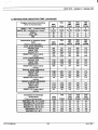
• Bit memory structure
Bit memory
Maximum
Size available on processor board
Type
of
Objects
4096
system bits SYi
128
input/output I/Oxy,i and RI/ROx,y,i
(1)
512
1024
(2)
Grafcet steps Xi
512
macro-steps XMi
64
internal bits Bi : up to the limit of the remaining space available
• Word memory structure
On-board RAM
RAM or EPROM
memory cartridge
24 Kwords (1)
48 Kwords (2)
32 Kwords(1)
32/64 Kwords(2)
data
program
constants
data (*)
program
constants
(*) in RAM only
(1)
for TSX and TPMX P47 400/405 processors
(2)
for TSX and TPMX P47 410/411/420/415/425/455 processors
• Application Structure
- Interrupt task : 1
- Master task : 1
- Fast task
:1
- Auxiliary task : 2
3/7
A
3.4-2 TSX and PMX 67-40 PLC
• Bit memory structure
Bit memory
Maximum
Size available on processor board
Type
of
Objects
4096
system bits SYi
128
input/output bits I/Oxy,i
2048
Grafcet steps Xi
512
macro-steps XMi
64
internal bits Bi : up to the limit of the remaining space available
• Word memory structure
On-board RAM
RAM or EPROM
Memory cartridge
96 Kwords
32/64/128 Kwords
Data
Program
Constants
Data (*)
Program
Constants
(*) in RAM only
• Application structure
- Interrupt task : 1
- Master task : 1
3/8
- Fast task
:1
- Auxiliary task : 4
3
User memory
A
3.4-3 TSX/PMX 87-40 and TSX/PMX 107-40 PLC
• Bit memory structure
Bit memory
Maximum
Size available on processor board
Type
of
objects
4096
System bits SYi
128
Input/Output bits I/Oxy,i
2048
Grafcet steps Xi
512
macro-steps XMi
64
Internal bits Bi : up to the limit of the remaining space available
• Word memory structure
On-board RAM
RAM or EPROM
memory cartridge
96 Kwords
64/128/256 Kwords
data
program
constants
data (*)
program
constants
(*) in RAM only
• Application Structure
- Interrupt task : 1
- Master task : 1
- Fast task
:1
- Auxiliary task : 4
3/9
A
3.4-4 Memory configuration rules
The following memory configuration rules must be observed :
For all V4 and V5 level PLCs
• The on-board RAM can contain data and also programs and/or constants
• The types of memory cartridges that can be used are :
- For the data : CMOS RAM only
- For the program : EPROM or CMOS RAM, the latter being necessary during the
writing and debugging of the program
- For the constants and IDP : EPROM or CMOS RAM
• Use of the constants memory zone is optional.
3/10
Single task software structure
4
A
Single task software structure
Sub-section
Section 4
Page
4.1 Description of the Master task
4/2
4.2 Single task programming
4/3
4.2-1 Program modules
4/3
4.3 Single task program execution
4/4
4.3-1 Execution cycle
4.3-2 Effect of an overrun
4/4
4/5
This section ends on page
4/6
4 / 1
A
4.1
Description of the Master task
The program of a single task application is contained in a single task called the
Master task. The Master task is a periodic task that is executed as shown below
within a period of time defined by the user.
The period of the Master task can be configured by the user to any period between
15 and 255 ms. The period selected must be sufficient to allow the following
operations to be performed.
Acquisition of the inputs
Acquisition of the inputs includes :
• Acquisition by the system of the system bits
and words (1).
• Transfer of the image of any data values
requested by the terminal connected to the
PLC in debug mode (1).
• Acquisition by the Data memory of any
messages from intelligent modules or
TELWAY, MAPWAY, ETHWAY, FIPWAY
and/or FIPIO network modules (2).
• Writing the TELWAY, MAPWAY, ETHWAY
and/or FIPWAY common words (COM) to
the Data memory.
• Writing the states of the input bits (I and RI)
of the remote I/O default bits (RD) to the bit
memory.
• Writing the input register words (IW) of the
intelligent modules to the Data memory
• Processing of terminal requests (1).
User program scanning
Period
Acquisition
of inputs
User Program
Scanning
Updating
of outputs
Transmission
of messages
The user program is then scanned.
Updating of the outputs
Updating of the outputs includes :
• Updating by the system of the system bits and words (1).
• Transmission of messages to the intelligent modules and TELWAY or MAPWAY
or ETHWAY network modules (2).
• Transmission of the 4 COM words to the TELWAY or FIPWAY network module
• Transmission of up to 64 COM words (COM, COMB, COMC, COMD) to the
MAPWAY or ETHWAY network module.
• Writing the states of the output bits (O and RO) to the I/O modules.
• Writing the output register words (OW) to the intelligent modules.
(1)
(2)
Only these operations are performed when the PLC is stopped.
On each cycle of the Master task, one message can be received from the intelligent
modules or network modules, and one message can be transmitted.
4 / 2
4
Single task software structure
A
4.2
Single task programming
4.2-1 Program modules
The program of the Master task is divided into several program modules which are
assembled differently according to whether or not Grafcet language is used for the
sequential processing section of the program.
Without Grafcet
With Grafcet
Pre-Processing
Lit or Lad
PRL
MAIN
Program
Sequential Processing
Subroutine
Subroutine
Subroutine
SRi
SR1
Lit
or
SR0
Lit Lad
or
Lit Lad
or
128 SR
Lad
max.
Lit
or
Lad
CHART
XM
Subroutine
Subroutine
SRi
Grafcet:
Subroutine
SR1
with
Lit
actions and
or
SR0
transitions
Lit Lad
in Lit or Lad
or
Lit Lad
or
128 SR
Lad
max.
Post-Processing
Lit or Lad
POST
Ladder or Literal language modules : MAIN, SR, PRE, POST
• Each module is written in a single language : Ladder or Literal.
• Modules written in different languages can be mixed within the Master task. For
example, a Main program module written in Literal can call a subroutine written in
Ladder, which can in turn call a subroutine written in Literal.
• The subroutines are assigned to the whole of the task. Eight levels of subroutine
nesting are permitted.
Grafcet language modules : CHART, XM
These modules are reserved for writing the Main Chart and Macro-steps (XM) of the
Sequential Processing Section in Grafcet language. The associated actions and
transition conditions are written in Ladder or Literal language.
Without Grafcet
With Grafcet
1st segment UCS
MAIN
Interpreter, CHART, XM and SR
2nd segment UCS
SR
PRE, POST, Actions and Transitions.
3rd segment UGS
4th segment
All the non-executable code of the Master task
Program source code for monitoring OFBs that support
alarm memorization
• The number of Ladder networks or Literal statements programmed in a module is
limited by the length of the segments in which it is stored : 32K maximum per
segment.
• Each module can contain a maximum of 255 Ladder networks or Literal statements,
which can be identified by a label numbered from 1 to 999.
4 / 3
A
4.3
Single task program execution
4.3-1 Execution cycle
To ensure the correct execution of the Master task, it is protected by two system tasks, the
Pilot task and the Monitoring task. These two system tasks are transparent to the user.
The Pilot task has the highest
priority but is executed only if
External
Internal
events
events
certain external or internal events
occur (change from RUN to STOP,
-RUN/STOP -Software
power break, hardware or software
command
fault
-Mains
faults, etc.).
break
Execution of the Master task
-Change of
(comprising acquisition of the incartridge
puts, scanning of the user program
and updating of the outputs) is
+
triggered by the clock pulse of the
Pilot Task
user-defined period. If the Master
task is correctly executed (i.e. its
execution time does not exceed
theuser-definedperiod), the Monitoring task then checks the
Period
correct operation of all the rackmounted or remote I/O modules.
During normal operation, this task
is executed when requested by
Master Task
the Pilot task (warm restart,
change of application) or in the
Inputs
interval between the end of the Supervisor
Priority
Master task and the arrival of the
User program
next periodic clock pulse (since
the real execution time of the
Outputs
Master task must always be
shorter than the user-defined
period). Occasionally, the execution time of the Master task may
Monitoring Task
overrun the user-defined period
due to :
Monitoring of correct
operation of I/O modules
• An excessive number or length
of subroutines.
• The execution of an iterative
phrase.
• The execution of an upstream jump.
• An excessive activation of Grafcet steps.
• An excessive exchange of messages (with intelligent I/O modules, or with the
terminal).
• A cold restart requested by the terminal.
When this occurs, the "overrun" system bit SY19 is set to 1. However, this condition
does not necessarily halt the program, since the system may be able to absorb the
overrun (if it is not too large or permanent) as described on the next page.
4 / 4
Single task software structure
4
A
4.3-2 Effect of an overrun
When the execution time of the Master task overruns the user-defined period of the
task :
• The ongoing scan cycle of the Master task is completed (with updating of the
outputs) and the "overrun" system bit SY19 is set to 1.
• The scan cycle of the Master task is then repeated continuously, without waiting
for the periodic clock pulse and without the execution of the Monitoring task, in an
attempt to absorb the overrun.
Depending on the nature of the overrun, two cases can then occur :
If the overrun is short and/or occasional, the system will be able to absorb the
overrun during the execution of several continuous cycles of the Master task.
During this time, system bit SY19 is set to 1 at the end of each cycle and must
therefore be reset to 0 by the user program after the overrun is absorbed.
Warning : A large occasional overload can cause desynchronization between the
Master task and the periodic exchange sampling on FIPIO. This can lead to :
- no updating of data used by the Master task
- loss of "transient" status set during the task cycle on exiting the task.
If the overrun is too long and/or permanent, the system will not be able to
absorb the overrun before the difference between the number of cycles executed
and the number of clock pulses received reaches the limit of 8. When this limit is
reached it causes a non-blocking software fault which is indicated by :
• Immediate stopping of the execution of the Master task (the PLC switches from
RUN to STOP).
• The RUN light goes out and the MEM light comes on.
To restart the Master task it is necessary to :
• Connect the terminal.
• Initialize the processor by pressing the INIT soft key.
• Restart the Master task by pressing the RUN soft key. If system bit SY19 is not
reset by the program it must be reset via the terminal in Adjust or Data mode.
The Master task cycle is then restarted from the beginning, with the data context
unchanged.
In order to avoid this kind of fault (unless it is caused by a programming error), it
is recommended :
• To increase the period of the Master task, or preferably
• To restructure the program by using the Auxiliary tasks.
Note :Case of a Master task period of more than 125 ms. If the execution time of the Master
task exceeds 1 second (due to a loop in the program), the overrun causes a blocking
software fault which is indicated by :
• Immediate stopping of the PLC.
• The RUN light goes out and the CPU, MEM and I/O lights come on.
To restart the PLC is then necessary to :
• Power down the PLC.
• Power up the PLC (cold restart).
4 / 5
A
4 / 6
Multitask software structure
5
A
Multitask software structure
Sub-section
5.1 Multitask processing
5.1-1 Description
5.1-2 User tasks and System tasks
5.2 Periodic Tasks
5.2-1
5.2-2
5.2-3
5.2-4
5.2-5
5.2-6
Principle
Organization of the User tasks
States of a Periodic task
Operation of Periodic tasks
Time management
Overruns
Section 5
Page
5/2
5/2
5/3
5/4
5/4
5/4
5/5
5/5
5/7
5/8
5.3 Organization of Periodic tasks
5/9
5.3-1 Interaction of tasks
5.3-2 Use of Auxiliary tasks
5/9
5/10
5.4 Operating modes of Periodic tasks
5/12
This section ends on page
5/14
5/1
A
5.1
Multitask processing
5.1-1 Description
In multitask processing, the various control requirements of the application are
divided into functional sub-assemblies (such as communication, analog
measurement and regulation, positioning, man-machine dialog, etc.). Each of these
functional sub-assemblies is then programmed independently in a separate task.
Up to six periodic tasks (with user-defined periods) can be programmed, plus an
interrupt task which is triggered by external events.
These tasks are then executed in parallel by the CPU, the priority between the
different tasks being organized by a "priority supervisor".
Supervisor
Period
Period
Period
External
events
Period
Period
Period
IT
Task
Fast
Task
Master
Task
Auxiliary
Tasks
AUX 3
AUX 3
AUX 1
IT
FAST
Positioning
Interrupt
task
MAST
AUX 0
Sequential
••••
••••
Dialog.
Measurement
Periodic tasks
+
Priority
-
The Master task contains the sequential processing and, as its name implies,
remains the basis of the application since it controls the activation of the other
periodic tasks. The number of tasks available with each type of PLC is described
in Section 3.4.
5/2
5
Multitask software structure
A
5.1-2 User tasks and system tasks
As in single task software structure, user tasks are protected by two system tasks :
the Pilot task and the Monitoring task. In the multitask structure, each task has a
certain priority which enables it to :
• Interrupt the execution of any task with a lower priority.
• Be interrupted by any task with a higher priority.
Pilot task : This task has the
highest priority but is executed
only if certain external or internal
events occur (change from RUN
to STOP, power break, hardware
or software faults, etc.).
Interrupt task : This is an
asynchronous user task that is
triggered by a signal from an
external device that requires
immediate processing, such as a
signal from a positioning module
for example.
Fast task : This is the periodic
task with the highest priority. It is
generally reserved for short
routines that recur frequently. Its
period is configurable from 5 to
255 ms.
+
Pilot
Task
(System)
IT
Task
Fast
Task
Supervisor
Priority
0
Master task : This task is
mandatory, since it contains the
sequential processing of the
application (usually written in
Grafcet) and activates the other
tasks by means of Control (CTRL)
function blocks. It is activated
automatically by the priority
supervisor and is configurable
from 5 to 255 ms.
Auxiliary tasks : These are
generally used for the slower
functions such as measurement
and regulation, operator dialogue,
diagnostic aids, etc. They are
configurable from 10 to 2550 ms.
User
Tasks
Master
Task
Auxiliary
Tasks
1
2
3
-
Monitoring
Task
(System)
Monitoring task : This is a transparent system task that checks the correct
operation of all the I/O modules.
Note : The bits and words of the Bit memory, the Data memory zone and the
Constants memory zone are common to all the user tasks.
5/3
A
5.2
Periodic tasks
5.2-1 Principle
The principle of multitask processing is based
on the execution of several tasks whose periods
of recurrence are defined by the user during
the application configuration.
The execution of each task is triggered by a
periodic clock pulse. The program assigned to
the task is then executed in its entirety before
the next clock pulse appears (i.e. within the
user-defined period).
Period
t
Clock pulse
Execution of
the task
Except for the Master task, which is always present, the presence of the other
periodic tasks (Fast task, Auxiliary task 0, Auxiliary task 2, etc.) must be declared
by the user during the application configuration, and the length of their periods must
run in ascending order so as to respect the following order of priority :
FAST → MAST → AUX0 → AUX1 → AUX2 → AUX3.
5.2-2 Organization of the User tasks
The priority of execution and the period of
recurrence of the various User tasks is
controlled and monitored by the priority
supervisor.
Period
Master task : The structure and execution of
the Master task is the same as in a single task
application (see Section 4.1).
Exchanges with
the terminal
Fast task and auxiliary tasks : Each of these
tasks has the same basic structure composed
of five different sections as follows :
Inputs I, IW
• Period : the user-defined period of the task.
• Exchanges with the terminal : transfer of the
data necessary for the real-time animation of
the screen when the terminal is used in the
Debug mode.
• Acquisition of the inputs : of the I/O modules
assigned to the task (these modules are
therefore removed from the data exchange
table of the Master task). These acquisitions
only apply to discrete bits and IW registers.
5/4
Main
Program
Outputs O, OW
SR
SR
5
Multitask software structure
A
• Scanning of the program : composed of a Main program module and up to 128
subroutine modules assigned to each task (128 SR maximum).
Each module can be written in either Ladder or Literal.
The rules of use and the capacity of the modules are the same as for the Master
task (without Grafcet) given in Section 4.2-1.
• Updating of the outputs : of the I/O modules assigned to the task, as described for
acquisition of the inputs.
Note :The reading and writing of messages from or to the intelligent modules, or TELWAY and
MAPWAY, ETHWAY or FIPWAY network modules, and of common words, must
always be programmed in the Master task.
5.2-3 States of a periodic task
Two parameters define the states of a periodic task :
• Executed or not executed, depending on the RUN or STOP command received
from the terminal. The command can be applied to any or all of the tasks.
• Activated or deactivated, depending on the execution of the associated task
control block (CTRL), which can be written in the program of any other task.
5.2-4 Operation of Periodic Tasks
▼
Periodic
clock pulse
▼
yes
▼
RUN task
yes
▼
Activate
task
▼
• Task activated, the execution
of task i then continues either
until it reaches the end of its
cycle, or until it is interrupted by
a task with higher priority. After
the execution of a task with higher
priority, the execution of task i
continues from where it was
interrupted.
Activate process to
copy RAM network
values (FIPIO only)
▼
yes
▼
Updating of rackmounted inputs
▼
• On power up, only the Master
task is active. The clock pulses
of the other tasks are generated.
• Activation of task i is requested
by the execution of the control
block CTRLi, which can be
written in any other task. Task i is
then executed when its clock
pulse is received and if all tasks
with higher priority have
completed their cycles.
▼
Activate
task
▼
End of process
to copy RAM
network values
yes
▼
Updating of
remote I/O
▼
Execution of user
program
▼
Updating of rackmounted and remote
I/O (FIPIO only)
▼
Activate process to
copy RAM network
values (FIPIO only)
▼
5/5
A
• Deactivation of task i :
This is requested by control block CTRLi. The task completes its cycle and
updates its outputs before being deactivated.
When a task is deactivated, or stopped, the inputs and outputs of the modules
assigned to the task are no longer updated.
Example :
In the following example, three periodic tasks have been configured, a Fast task, the
Master task and Auxiliary task 0. The System task, which is a monitoring task, is
executed when the user tasks have completed their cycles.
Tasks duration period
Fast
2.5ms 10ms
Master 15ms
Aux.
10ms
System
40ms
CTRL
AUX
0
CTRL
FAST
100ms
2.5ms
▲
▲
0
10
40
80
100
120
ms
period
execution time
Note
Distribution of I/O : rack-mounted or remote, has an effect on the execution of
a user task execution time (waiting period for the signal to indicate the end of
copying of the RAM network values may be long).
5/6
5
Multitask software structure
A
5.2-5 Time management
When a periodic task is activated, its execution is triggered by its associated clock
pulse and can be interrupted by a task with higher priority. The diagram below
illustrates the interruption of the Master task by a Fast task.
SINGLE TASK
Task
Master
MULTITASK
Tasks
Master
Fast
Inputs
Inputs
Program
Inputs
Outputs
Inputs
Program
Program
Outputs
Inputs
Outputs
Program
Outputs
Outputs
Inputs
Program
Outputs
5/7
A
Each task can be interrupted by a task with higher priority. The interrupting task is
then executed either completely, or until it is in turn interrupted by a task with higher
priority.
Since 10% of the total scan time of the program must be reserved for system tasks
and exchanges with the terminal, the sum of all the execution times of the
periodic tasks must not exceed 90% of the longest period.
Note :The timing of the various operations involved in the exchange of Text block messages
is controlled by the Master task, there is therefore no point in programming them in a
task that is faster than the Master task.
5.2-6 Overruns
In the case of an overrun of the period of a Fast task or an Auxiliary task, the system
reacts in the same way as for an overrun of the Master task (see Section 4.3-2). The
system absorbs the overrun if it is short or occasional, or stops the task if the overrun
is too long or permanent.
However, it should be noted that each periodic task has its own "overrun" system
bit SY19, which is significant only for the task in which it is tested. In order to make
a diagnostic check of task overruns, either by program or by using the terminal, it
is therefore recommended to transfer the image of system bit SY19 for each task
into internal bits. The diagnostic check can then be made on these internal bits,
which are the image of the SY19 of each task.
• Effect of an overrun of one task on the other tasks
In relation to the task that has overrun :
- The tasks with higher priority continue to be executed normally.
- The tasks with lower priority are interrupted during the time necessary for the
system to absorb the overrun.
If the system cannot absorb the overrun before the difference between the number
of cycles executed and the number of clock pulses received reaches the limit of
8, the program is stopped (see Section 4.3-2).
• Diagnostic check
By reading the internal bits that are the image of the SY19 of each task, it is
possible to detect the task that has overrun (bit at 1 = task overrun). If several of
these internal bits are at state 1, indicating that several tasks have overrun, it is the
task with the highest priority that originated the fault.
5/8
Multitask software structure
5
A
5.3
Organization of Periodic tasks
5.3-1 Interaction of tasks
As each new task of higher priority is introduced, the "free time" representing the
difference between the execution time of a task and its user-defined period is
reduced accordingly. When this free time is reduced beyond a certain point the
system stops, as there is insufficient time for the CPU to execute all the required
tasks (system tasks and user tasks) within the defined period.
A periodic task can therefore be characterized by two times :
• tr : which is the recurrence time, or period, of the task.
• te : which is the execution time of the task.
Assuming that the CPU is constantly using 90% of its capacity for the execution of
the user tasks (thus allowing 10% for system tasks and exchanges with the
terminal), the curve below shows the influence of a task of higher priority on a task
of lower priority.
The sum of the ratios te/tr of each task must be less than 90% :
te
< 90%
tr
The horizontal coordinates show
the characteristics of the Fast task
in relation to the vertical
coordinates of the Master task.
The curve shows that a Fast task
tr/te ratio of less than 2 imposes a
tr/te ratio on the Master task that
rapidly becomes unacceptable.
Example :
• Fast task : tr = 15 ms and
te = 4 ms, giving a tr/te ratio of
3.75.
• Master task : te = 60 ms. The
curve defines a tr/te ratio for the
Master task of 1.55, giving a
Master task period tr of 60 x 1.55
= 93, or about 95 ms.
tr
te
5
4
3
2
tr
te
1
2
3
4
1
Example of the influence of the Fast task on the Master task
5/9
A
5.3-2 Use of Auxiliary tasks
In a multitask program, the Auxiliary tasks can be used to reduce the period of the
Master task by transferring part of the program of the Master task to one or more
Auxiliary tasks.
The figures and curves given below assume that the CPU is constantly using 90%
of its capacity for the execution of the user tasks (thus allowing 10% for the system
tasks and exchanges with the terminal).
The horizontal coordinates indicate the desired percentage of reduction of the
period of the Master task.
The curves have been defined according to the amount of program (or execution
time) that is transferred from the Master task to the Auxiliary task.
The vertical coordinates indicate the ratio that will then exist between the period of
the Auxiliary task and the period of the new Master task.
Auxiliary period
Mast. period
15
10% 20% 30% 40% 50% 60% 70% 80% 90%100%
10
5
0
0
5/10
10
20
30
40
50
60
70
80
90 100 % Gain on Mast.
Multitask software structure
5
A
Example :
In a single task program, the period of the Master task is 100 ms. A 20 % reduction
of this period, in order to obtain a period of 80 ms, is desirable. An Auxiliary task is
therefore created so as to off-load the Master task.
From his knowledge of the program and its structure, the user decides which part
of the program of the Master task (represented by the execution time of this part of
the program) can be transferred to the Auxiliary task.
In this example, 30% of the execution time of the Master task is transferred to the
Auxiliary task.
Auxiliary period
Mast. period
10%
20%
30%
40%
50%
60%
5
3
0
0
10
20
30
40
50 % Gain on Mast.
By following the 30% curve shown above, it can be seen that the ratio of the periods
of the two tasks is 3. The period of the Auxiliary task is therefore :
tr = 3 x 80 (tr of Master task) = 240ms
The same method can be used to reduce the period of Auxiliary task 0 by creating
Auxiliary task 1, and so on.
5/11
A
5.4
Operating modes of Periodic tasks
A PL7-3 application can take the following states : N_CONF, IDLE, STOP, RUN,
FAULT.
N_CONF
APPLI
SY0
STOP
APPLI
▲
▲
▼
IDLE
APPLI
Init
▲
Run application
Run/Stop application
▼
▲
N_CONF TASK
RUN TASK
STOP TASK
BREAK TASK
INACTIVE TASK
5/12
RUN
APPLI
APPLI
FAULT
▲
Application fault
Multitask software structure
5
A
N_CONF APPLI
There are no user tasks. The only active system tasks are those which provide the
TELWAY, MAPWAY, ETHWAY, FIPWAY or FIPIO communication functions. The
processor does not control any rack-mounted or remote I/O modules. The state of
the discrete outputs is at 0 (1).
IDLE APPLI
User tasks and PL7-3 objects are in their default positions. There is no I/O
exchange, the image values in the processor and the discrete outputs are set to 0.
Image values in the processor, other than discrete values, are specific to the
managed function.
STOP APPLI
User tasks are stopped at the beginning of the cycle. The outputs of rack-mounted
modules are set to 0 or in the output safety state (following the value of SY8 and of bits
SY32 to SY39). The outputs of remote modules are set to the default value, defined in
the configuration : held at or defaulted to 0 or at 1(2).
(1) A TBX distributed I/O module can apply either default or retained values, if it has previously
been configured then controlled by a PL7-3 application. The configuration is lost if there
is a break in the power supply.
(2) A group of points takes the configured default values, when the controlling task sends the
application values on changing to STOP mode. The group of points loses the default
values when it is reconfigured (the system does not automatically reconfigure a group of
points). A preliminary learning phase defines the control procedure.
5/13
A
RUN APPLI
Each user task has a local state, which is dependent on programmed actions and
debug requests from the user.
• N_CONF TASK : the task is not configured. No I/O modules are assigned to it.
• RUN TASK : the memory image outputs are transmitted cyclically to the output
modules. These values are set in the physical interface of the module, except for
rack-mounted modules, where bit SY9 (outputs at 0) or bit SY116 (output controls
suspended) is at state 1.
• STOP TASK : the application is partially stopped. All the outputs of the rackmounted modules take the safety value 0, apart from the racks in which a retained
value has been configured : in this case, the module keeps the last output value.
Modules controlled by a task which is still in RUN mode continue to be updated.
Remote outputs controlled by the task in STOP mode take their default value; the
other remote outputs are not affected.
• BREAK TASK : stop for the task to be debugged. The task is stopped exactly at
the place defined by the breakpoint. The outputs behave in the same way as in
STOP TASK state.
• INACTIVE TASK : initial state in a RUN task from the IDLE application state (apart
from the Master task which triggers the execution of the task). To quit the inactive
state, it is necessary to program the START CTRL action for the task. When a
RESET CTRL action is performed (return to inactive state), the rack-mounted I/O
of the task are no longer updated and remain in this state whatever the safety
instruction is. The remote I/O take the default values or the safety values (if the
application has still not transmitted a significant value).
• DEFAULT TASK : for a RUN task outputs which have been controlled at least
once, take the default value or the safety value. During restart, each task in RUN
applies the values defined by the application (all tasks are set to the inactive state,
except the Master task).
If the break in the power supply is general, the configuration of TBX discrete
distributed I/O modules is lost and therefore the safety values are applied until the
first application value is received.
5/14
System bits and words
6
A
System bits and words
Sub-section
6.1 System bits
Section 6
Page
6/2
6.2 System words
6/10
6.3 System bits and words assigned to remote I/O
6/16
This section ends on page
6/16
6/1
A
6.1
System bits
TSX/PMX 47/67/87/107-40 PLCs have 128 system bits (SY0 to SY127) which
indicate the operating status of the PLC and/or allow its operating sequence to be
altered. The state of these bits should be tested in the user program so as to detect
events or types of operation that require special processing. Some of these system
bits must be reset to their initial or normal state by the program. However, the bits
that are reset to their initial or normal state by the system must not be reset by the
program or by the terminal.
System
bits
Function
Description
SY0
COLD RESTART
Normally at 0, set to 1 by :
• Changing a user cartridge
• Power return with loss of data (battery fault)
• The user program
• The terminal (in Adjust or Data modes).
Reset to 0 by the system after a normal scan of the
program.
On a cold restart, the PLC always restarts in RUN
mode, if this is defined in the configuration (RUN
AUTO).
Operation : see Section 7.2-3 "Response to a Cold
Restart".
SY1
WARM RESTART
Normally at 0, set to 1 by :
• Opening a user cartridge lock
• Power return with saved data
• The user program
• The terminal (in Adjust or Data modes).
Reset to 0 by the system before the first updating of
the outputs.
Operation : see Section 7.2-2 "Response to a Warm
Restart".
SY2
IMMEDIATE
RESTART
Normally at 1. Can be reset to 0 by the program to
select an immediate restart after a power break of
less than the autonomy of the system (about 200 ms),
the bit is then set to 1 by the system. The length of
the power break is given in system word SW5.
Operation : see Section 7.2-1 "Response to an
Immediate Restart".
6/2
6
System bits and words
A
System
bits
Function
SY3
"STOP-FREE-INIT" When the key is set to :
key on the front of
• STOP : the bit SY3 is at 0
the TSX 87-30
• FREE : the bit SY3 is at 1.
When the key is turned to STOP, the PLC stops and
Bit not used
can only be restarted by using the terminal to set it
by other PLCs
to RUN, or by a Cold restart with the key set FREE.
The bit SY3 can be used to detect, by program,
whether the PLC was voluntarily stopped by using
the key.
SY4
SY5
SY6
SY7
10ms TIME BASE
100ms
1sec.
1min
SY8
RACK-MOUNTED Normally at 1. Can be reset to 0 by the program
SAFETY
or by the terminal (in the Adjust or Data modes) :
OUTPUTS (general) • State 1 : Resets the rack-mounted outputs to 0
(depending on the states of bits SY32 to SY39) if
the program is not executed normally.
• State 0 : Holds the rack-mounted outputs in their
existing state if the program is not executed normally
(the states of bits SY32 to 39 then have no effect).
SY9
SY10
Description
Bits whose change of state is controlled by an
internal clock. They are asynchronous in relation to
the operation of the PLC.
RACK-MOUNTED
OUPUT RESET
Normally at state 0. Can be set to 1 by the program
or the terminal (in Adjust or Data modes) :
• State 1 : Forces the rack-mounted outputs to 0 (when the
program is running).
• State 0 : The rack-mounted outputs are updated normally.
I/O FAULT
(general)
Normally at 1. Is reset to 0 on detection of the
following faults :
• There is a fault in an I/O module in the basic rack or
extension rack (configuration not compatible, exchange
fault, module or terminal block missing, I/O module
fault).
• There is a fault in the extension rack (power supply fault,
connection fault, or fault in the terminal block number).
• There is a fault in the equipment connected on
FIPIO (configuration of non FIP module, exchange
fault, fault in one of the equipment modules, power
supply fault, fault in the equipment power supply or
an incorrect connection point).
• There is a fault on the FIPIO link (fault on link,
incorrect processor connection code, conflict with
channel master on FIPIO).
When SY10 is at 0 either SY118 or SY119 is also at 0.
(The corresponding I/O fault bit SY40 to SY47 is also reset
to 0). The bit SY10 is set to 1 when the fault disappears.
6/3
A
System
bits
Function
Description
SY11
MAPWAY,TELWAY,
ETHWAY or FIPWAY
COM WORD
UPDATING
Normally at 0. Is set to 1 as soon as a station transmits
its COM words on the network.
Can be reset to 0 by the program or the terminal
in order to check for the exchange of COM words.
SY12
NETWORK 1
IN OPERATION
Normally at 0. Is set to 1 as soon as a station exchanges data with at least one other station. Does not
indicate that all the stations are operating.
Is reset to 0 if there is a fault in the network module.
SY13
NETWORK 2
IN OPERATION
As SY12.
SY14
NETWORK 3
IN OPERATION
As SY12.
SY15
NETWORK 4
IN OPERATION
As SY12.
SY16
I/O FAULT (*)
(task)
Normally at 1. Is reset to 0 by a fault in any of the I/O
modules that are configured in the task concerned :
• Identical to SY10 for rack-mounted modules.
• For remote modules : exchange fault between
processor and equipment on FIPIO, internal
equipment fault, fault in the discrete process on at
least one input or output of a module (break in one
or all outputs, terminal block fault, fault in the
process power supply).
SY16 must be reset to 1 by the user program.
SY17
(*)
CARRY
OVERFLOW (*)
(unsigned
arithmetic)
Normally at 0. Is reset to 1 for an overflow of capacity
in unsigned arithmetic operations. It then represents
the absolute maximum value (65536 in single length
and 4 294 967 296 in double length). In circular shift
operations, it indicates the shift out of a bit at state 1.
Must be tested by the user program after each
operation where there is a risk of an overflow and
must then be reset to 0 after the overflow.
System bit that is significant only for the task in which it is tested
(see the end of this Section).
6/4
System bits and words
6
A
(*)
System
bits
Function
Description
SY18
ARITHMETIC
OVERFLOW (*)
(signed arithmetic)
Normally at 0. Is reset to 1 for an overflow of capacity
in signed arithmetic operations on :
• A single length word : the result is more than
+32767 or less than -32768.
• A double length word : the result is more than
+2 147 483 647 or less than -2 147 483 648.
Must be tested by the user program after each
operation where there is a risk of overflow and must
then be reset to 0 after an overflow.
SY19
TASK
OVERRUN (*)
Normally at 0. Is set to 1 if the period of the task is
exceeded (execution time of the task greater than the
user-defined period). A prolonged overrun stops the
PLC and the MEM light comes on.
Is reset to 0 by the user program.
Operation : see Section 4.3-2.
SY20
INDEX
OVERRUN (*)
(task)
Normally at 0. Is set to 1 when the address of an
indexed object becomes less than 0 or exceeds the
number of objects declared in the configuration.
Must be tested by the user program after each
operation where there is a risk of overrun and must
then be reset to 0 after an overrun.
Operation : see Section 2.5-2.
SY21
GRAFCET
INITIALIZATION
(general)
Normally at 0. Is set to 1 by :
• A cold restart, SY0 = 1
• The user program, in the Preprocessing section
only
• The terminal (initialization by pressing the INIT soft
key, or by program modification in the connected
mode).
When at state 1, it causes initialization of Grafcet : the
active steps are deactivated and the initial steps are
activated. Is reset to 0 by the system during execution
of the Sequential processing section.
System bit that is significant only for the task in which it is tested
see the end of this Section).
6/5
A
System
bits
Function
Description
SY22
GRAFCET
RESET
Normally at 0. Can be set to 1 by the user program in
the Preprocessing section only.
When at state 1, it causes deactivation of all the
Grafcet steps.
Is reset to 0 by the system during execution of the
Sequential processing section.
SY23
GRAFCET
FREEZE
Normally at 0. Can be set to 1 by the user program in
the Preprocessing section only.
When at state 1, it freezes the Grafcet chart in its
current state (no evolution of steps).
Must be reset to 0 by the user program in the
Preprocessing section only, so as to unfreeze the
Grafcet chart and permit normal evolution of the
steps.
SY24
MACRO-STEP
RESET
Normally at 0. Can be set to 1 by the user program in
the Preprocessing section only.
When at state 1, it permits resetting to 0 of the macrosteps designated by system words SW8 to SW11 :
• SW8 : bits 0 to F reset macro-steps 0 to 15
• SW9 : bits 0 to F reset macro-steps 16 to 31
• SW10 : bits 0 to F reset macro-steps 32 to 47
• SW11 : bits 0 to F reset macro-steps 48 to 63.
The macro-step is reset to 0 when SY24 changes to
1 and when the system word bit representing the
macro-step is at 0.
The bits of words SW8 to SW11 are set to 1 by the
initialization of the Grafcet chart (SY21 = 1).
SY24 is reset to 0 by the system during execution of
the Sequential processing section.
SY25
MULTI-ACTIVITY
Normally at 0. Is set to 1 as soon as a mono-active
macro-step becomes multi-active. This bit enables
the user to monitor the steps that have been declared
mono-active without affecting the sequential
processing. The number of a macro-step that has
become multi-active can be read in system words
SW12 to SW15 (see Section 6.2). SY25 can be reset
to 0 by the user program or by the terminal.
6/6
System bits and words
6
A
System
bits
Function
Description
SY26
ACTIVATION
OVERRUN
Normally at 0. Is set to 1 when the possibilities of
activation of steps or transitions have been overrun
(see Divider B "Grafcet Language" Section 3.4).
When this occurs, the PLC stops and the MEM light
comes on. System bit SY19 ("Task overrun") is also
set to 1. To restart the PLC, connect the terminal and
press the INIT and RUN keys. SY21 is reset to 0 by
this initialization by the terminal.
The number of simultaneously active steps and
simultaneously enabled transitions in the cycle before
the overrun can be read in system words SW6 and
SW7 respectively.
SY27 to
SY31
/
SY32 to
SY39
OUTPUT
SAFETY
(racks)
Not used.
Normally at 1. Can be reset to 0 by the user program
or by the terminal (in the Adjust or Data modes).
These bits are complementary to the "output safety"
bit SY8 and are assigned to the outputs of the basic
and extension racks as follows :
Bits
SY32 SY33 SY34 SY35 SY36 SY37
Racks 0/1
2/3
4/5
6/7
8/9
A/B
Bits
SY38 SY39
Racks C/D E/F
When SY8 is at 1, these bits enable the user to force
the outputs of selected racks to 0, or to hold them in
their existing states if the program is not executed
normally.
When SY32 to SY39 are at 1, the outputs of the
corresponding racks are forced to 0 if the program is
not executed normally.
When SY32 to SY39 are at 0, the outputs of the
corresponding racks are held in their existing states
if the program is not executed normally.
Operation : see Section 9.3.
6/7
A
System
bits
Function
Description
SY40 to
SY47
I/O FAULT
(racks)
Normally at 1. These bits are reset to 0 by an I/O fault
in the corresponding racks, as follows :
Bits
SY40 SY41 SY42 SY43 SY44 SY45
Racks 0/1
2/3
4/5
6/7
8/9
A/B
Bits
SY46 SY47
Racks C/D E/F
The resetting to 0 of one of these bits by an I/O fault
causes :
• The setting to 0 of the general fault bit SY10
• The I/O light of the processor module comes on
• The I/O light of the corresponding rackmaster
module comes on, if the fault is in an extension rack
(racks 2 to F)
• Bit I/Oxy,S of the faulty module is set to 1.
SY40 to SY47 are then set to 1 after the fault
disappears
By using the various I/O fault bits (i.e. SY10, SY16,
SY40 to SY47, and I/Oxy,S) the user can define a
comprehensive fault processing structure (see Section
9.4).
SY48
Reading of periodic Normally at 0, this bit can be set to 1 or to 0 by the
task execution
program or the terminal.
times
If SY48 = 0, system words SW40 to SW46 indicate
the execution time of the longest cycle in each task.
If SY48 = 1, system words SW40 to SW46 indicate
the execution time of the last cycle in each task (refer
to the description of system words SW40 to SW46 in
Section 6.2).
SY49 to
SY50
Real-time clock
reading/writing
6/8
Normally at 0 (by default), these two bits can be set
to 1 or 0 by the program or the terminal.
SW49 = 0 and SW50 = 0 : permits reading of the
current date and time in system words SW50 to
SW57.
SW49 = 0 and SW50 = 1 : permits writing of the date
and time in system words SW50 to SW57 (necessary
after a power break).
SW49 = 1 and SW50 = 0 : permits reading of the date,
time and cause of the last stop in system words SW50
to SW57 (see system words SW50 to SW57 in
Section 6.2).
6
System bits and words
A
System
bits
SY51
SY52
Function
Description
/
Reset message
counters
System bit reserved
System bits reserved
SY53 to
SY99
/
System bits not used
SY100 to
SY115
Integral UNI-TELWAY
option
System bits reserved
SY116
Suspend
rack-mounted
output commands
This bit at state 1 causes the updating of discrete
Register outputs and of all rack-mounted modules.
SY117
Suspend acquisition
of rack-mounted
inputs
This bit at state 1 causes the acquisition of discrete
inputs and Registers of all rack-mounted modules
to be suspended.
SY118
Remote I/O
fault
Normally at state 1, this bit is set to 0 when a fault is
detected on a device on FIPIO. The causes of
the fault are listed in the description of SY10.
SY119
Rack-mounted
I/O fault
Normally at state 1, this bit is set to 0 when a fault is
detected in a rack-mounted module. The causes
of the fault are listed in the description of SY10.
SY120 to
SY127
/
System bits not used
(*)
Note on the system bits assigned to each task
System bits SY16 to SY20 are specifically assigned to each of the tasks configured
(IT, FAST, MAST, AUX0 to AUX3). These system bits are therefore significant only
for the task in which they are tested.
Example : If an arithmetic operation in the Fast task causes an overflow, system bit
SY18 in the Fast task is set to 1, i.e. :
• SY18 tested by program in Fast task equals 1
• SY18 tested by program in the Master task or Auxiliary tasks equals 0, since the
overflow in question is not due to an operation written in these tasks. The resetting
of these bits must therefore be written in the same task that caused their change
of state.
If it is necessary to test the states of system bits SY16 to SY20 in another task, this
can be done by copying their states into five internal bits in the original task and then
testing the states of these internal bits in the other task.
Note : When accessed by the terminal in Adjust or Data modes, system bits SY16
to SY20 concern only the Master task. Similarly, system bits SY21 to SY26,
which concern Grafcet programming, are assigned only to the Master task,
since Grafcet can be written only in the Master task.
6/9
A
6.2
System Words
The TSX/PMX 47/67/87/107-40 PLCs have 128 system words (SW0 to SW127)
described below :
System
words
Function
Description
SW0
Com Word
Updating
The 16 bits of this word (0 to F) represent the first 16
stations on the network. When one of these bits is at
state 1, it indicates that the corresponding station on
the network has broadcast its COM words (and therefore that the PLC in the station concerned is set to
RUN).
After a change of state, the bits concerned must be
reset to 0 by the user program.
SW1
/
Reserved.
SW2
Primary
Station
Number
Indicates in decimal, for the primary network :
• Station number (LSB) = 0 to 127
• Network number (MSB) = 0 to 63.
Unused bits remain at 0.
SW3
Primary
Network
Stations
The 16 bits of this word (0 to F) represent the first
16 stations on the network. When at state 1, it
indicates that the network module of the corresponding station is operating correctly (Telway only).
These bits are updated by the system.
SW4
/
Reserved.
SW5
Immediate
Restart
Time
This word contains the time in milliseconds of the
power break in the case of an immediate restart, i.e.
when the duration of the break is less than the
autonomy of the power supply of the PLC (see SY2
in Section 6.1). The value of this word is updated after
each immediate restart.
SW6
Table of active
Grafcet steps
This word contains the number of memory locations
occupied in the table of active steps, i.e. the number
of steps that are active, that are being activated and
that are being deactivated in one cycle.
This word is updated by the system after each evolution
of the Grafcet chart, i.e. at the end of the Master task.
See SY26 in Section 6.1.
6/10
System bits and words
6
A
System
words
Function
Description
SW7
Table of
enabled
Grafcet
transitions
This word contains the number of memory locations
occupied in the table of enabled transitions, i.e.
the number of transitions that are enabled, that are
cleared and that are becoming enabled in one cycle.
This word is updated by the system after each evolution
of the Grafcet chart, i.e. at the end of the Master task.
See SY26 in Section.
SW8 to
SW11
Table of
macro-steps
Each bit of these 4 words represents one of the 64
macro-steps of the Grafcet chart.
Normally at 1, these bits can be reset to 0 by the user
program. The corresponding macro-step is reset to 0
when SY24 changes to 1 and when the system word
bit representing the macro-step is at 0. See SY24 in
Section 6.1.
SW12 to
SW15
Table of
mono-active
macro-steps
Each bit of these 4 words represents one of the 64
macro-steps of the Grafcet chart.
Normally at 0, these bits change to 1 when the
corresponding mono-active macro-step becomes
multiactive, which also sets system bit SY25 to 1.
After being tested, these words must be reset to 0 by
the user program or the terminal. The setting to 1 of
system bit SY21 (Grafcet initialization) also resets
system words SW12 to SW15 to 0.
SW16 to
SW18
Copy part of the
RAM_SYSTEM
These words allow part of the RAM_SYSTEM field to
be copied to Wi internal words :
• SY16 contains the start of destination Wi address,
• SY17 contains the start address of the
RAM_SYSTEM field to copy,
• SY18 contains the number of bytes to copy.
SW19
Modify the period
of periodic tasks
This word lets the user modify the period of a user
task. To modify a period, this word must contain :
• The value of the new period defined in the time base
configured for the corresponding task (LSB),
expressed as a hexadecimal value,
• The number of the task to be modified (2 = Fast task,
3 = Mast. task, 4 to 7 = Aux. tasks 0 to 3).
task n°
Period
FAST/MAST : in ms,
AUX
: in x10ms
6/11
A
System
words
Function
Description
SW20 to
SW21
System operating
time
These words contain the time that has elapsed since
the last cold restart or the setting to 1 of SY0, not
including power breaks (*) (time base 100 ms).
They are updated by the system.
SW22 to
SW23
Application
operating time
These words contain the time that has elapsed since
the last cold restart or the setting to 1 of SY0,
including power breaks (time base 100 ms).
They are updated by the system.
SW24
/
Reserved.
SW25
/
Reserved.
SW26 to
SW39
Message counters
Reserved.
SW40 to
SW46
Task execution
times
The system controls one word for each task. The
states of these words can be read :
If SY48 = 0, system words SW40 to SW46 indicate
the execution time of the longest cycle in each task.
If SY48 = 1, system words SW40 to SW46 indicate
the execution time of the last cycle in each task.
The value of the word corresponds to the time elapsed
between the start of the cycle of the task (reading of
the inputs) and the end of the cycle of the task
(updating of the outputs), and taking into account the
interruptions caused by tasks with a higher priority.
SW40 : Fast task
SW41 : Master Task
SW42 : Auxiliary task 0
SW43 : Auxiliary task 1
SW44 : Auxiliary task 2
SW45 : Auxiliary task 3
SW46 : Interrupt task
SW47 to
SW49
(*)
/
Reserved.
Setting SY0 to 1 from the terminal is not considered a cold restart.
6/12
System bits and words
6
A
System
words
Function
Description
SW50 to
SW57
Real-time clock
reading/writing
Depending on the states of system bits SY49 and
SY50 these words contain either :
• the current date and time, or
• the date, time and cause of the last stop.
SW50 = always at 0
SW51 = seconds (0 to 59)
SW52 = minutes (0 to 59)
SW53 = hours (0 to 23)
SW54 = days (1 to 31)
SW55 = months (1 to 12)
SW56 = years (0 to 9999)
SW57 = the day of the week (0 to 6), when reading
and writing the current date and time, or
SW57 = the code indicating the cause of the last
stop when reading the date, time and cause
of the last stop. This code is as follows :
1 = switched from RUN to STOP by the terminal
(or the key on the front of the processor)
2 = stopped by a software fault (task overrun or
Grafcet overrun)
3 = switched from "FREE" to "INIT" by the key
on the front of the processor
4 = stopped by a power break, or by opening a
user cartridge lock
5 = stopped by a hardware fault
6 = stopped by a Halt instruction.
SW58 to
SW59
/
Reserved.
SW60
Serious error code
System word reserved.
SW61 to
SW63
Unknown NPCALL
code
System word reserved.
SW64 to
SW72
First controlled
network module
(multiple networks)
• SW64 to 67 : These words contain the COM word
refresh indications for the stations (0 to 63) on this
network (refer to the description of SW0).
• SW68 to SW71 : These words contain the states of
the network modules (0 to 63) (Telway only) (refer
to the description of SW3).
• SW72 : This word contains the network address of
the first module (refer to the description of SW2).
6/13
A
System
words
Function
Description
SW73 to
SW81
Second controlled
network module
(multiple networks)
• SW73 to 76 : These words contain the COM word
refresh indications for the stations (0 to 63) on this
network (refer to the description of SW0).
• SW77 to SW80 : These words contain the states of
the network modules (0 to 63) (Telway only) (refer
to the description of SW3).
• SW81 : This word contains the network address of
the first module (refer to the description of SW2).
SW82 to
SW90
Third controlled
network module
(multiple networks)
• SW82 to 85 : These words contain the COM word
refresh indications for the stations (0 to 63) on this
network (refer to the description of SW0).
• SW86 to SW89 : These words contain the states of
the network modules (0 to 63) (Telway only) (refer
to the description of SW3).
• SW90 : This word contains the network address of
the first module (refer to the description of SW2).
SW91 to
SW99
Fourth controlled
network module
(multiple networks)
• SW91 to 94 : These words contain the COM word
refresh indications for the stations (0 to 63) on this
network (refer to the description of SW0).
• SW95 to SW98 : These words contain the states of
the network modules (0 to 63) (Telway only) (refer
to the description of SW3).
• SW99 : This word contains the network address of
the first module (refer to the description of SW2).
SW100 to
SW115
Registers for built-in These words are the register words for the
Uni-Telway
Uni-Telway connector located on the front panel of
connector
certain processor modules :
• SW100 : status word
• SW101 and 102 : event data status word
• SW103 to SW107 : reserved words
• SW108 : command word
• SW109 to SW115 : reserved words.
6/14
System bits and words
6
A
System
words
Function
Description
SW116
Remote I/O fault
This word indicates a communication fault on FIPIO,
between (task) the processor and a module in the
task concerned. Each bit at 1 indicates a specific
fault :
• B0 global invalidity : serious fault in all task
equipment (all modules missing, non-operational
FIPIO).
• B1 Invalid values : one or more variables have
never been exchanged with a TBX (TBX is absent
or incompatible with the configured type).
• B2 Total absence of update : no data has been
updated since the previous cycle. It shows a major
inconsistency between the task period and the bus
activity.
• B3 Partial absence of update : data exists which
has not been updated since the previous cycle. It
shows a major inconsistency between the task
period and the bus activity.
• B4 Total dialogue fault : dialogue fault between
the processor and all the equipment (interference
on network, break in tap link, equipment missing).
• B5 Partial dialogue fault : dialogue fault between
the processor and some of the equipment
(interference on network, break in tap link, equipment
missing).
• B6 Total update fault : all the equipment being
configured.
• B7 Partial update fault : equipment being
configured or only partially present (extension
missing).
SW117
SW118 to
SW121
SW122 to
/
Remote I/O fault
(equipment)
/
System word not used
Each bit in this group of words is significant
for the state of a connection point. The presence of
a bit at 0 indicates the appearance of an exchange
fault or a fault in the discrete process with the
equipment : SW118,0 = equipment at connection
point 0, etc.
System words not used
SW127
6/15
A
6.3
System bits and words assigned to remote I/O
System bits and words, assigned to remote I/O, are updated by User tasks or
Monitoring tasks, in accordance with the following algorithm :
Monitoring task
If
there is a module missing or a configuration fault in the equipment,
an internal fault in the equipment or a data exchange fault is detected,
an external fault is detected outside the equipment (short circuit, open
circuit, etc).
Then SW11i,j is set to state 0
SY118 is set to state 0
SY10 is set to state 0
the I/O indicator lamp is on.
If not SW11i,j is set to state 1,
global objects of all peripheral equipment are updated.
Periodic task
If
a communication fault or a fault in a channel of the equipment is detected.
Then SY16 is set to 0
SW11i,j is set to 0
SY118 is set to 0
SY10 set to 0.
6/16
Power break/return
7
A
Power break/return
Sub-section
7.1 Principle
7.1-1 Response to a power break
7.1-2 Saving of a coherent application context
7.1-3 Response to a power return
7.2 Response to a power return in a single task program
7.2-1 Response to an immediate restart
7.2-2 Response to a warm restart
7.2-3 Response to a cold restart
7.3 Response to a power return in a multitask program
7.3-1 Response to an immediate restart
7.3-2 Response to a warm restart
7.3-3 Response to a cold restart
This section ends on page
Section 7
Page
7/2
7/2
7/2
7/3
7/4
7/4
7/6
7/8
7/10
7/10
7/10
7/10
7/10
7/1
A
7.1
Principle
To avoid incorrect operation of the automated system in the case of a mains power
break or power drop, the power supply modules of TSX/PMX 47/67/87/107-40
PLCs are provided with :
• A mains power OK detector.
• A mains power failure detector, that can be switched on or off by the user.
The PLC is delivered ex-factory with this failure detector set to ON.
• An autonomy of operation of about 200 ms after a power break.
These devices enable the PLC to respond correctly to each type of power break, to
stop the program scan before the inputs are reset to zero, and to minimize the delay
in restarting the system after mains power returns.
7.1-1 Response to a power break
Duration of power break
PLC response
Micro-cut of less than 10ms
• Normal program execution.
Break of more than 10ms but
less than the autonomy of the
power supply (200ms)
• Program scan is stopped before the
inputs are reset by the PLC power
break.
• Saving of a coherent application
context.
• Downtime is totalled in SW5.
• If SY8=1 the rack-mounted outputs
are forced to 0.
if SY8=0 the rack-mounted outputs
are maintained.
• Remote outputs, which are already
controlled, are set to a default value
defined in the configuration. The other
remote outputs are set to a safety
value.
• The processor stops.
Break of more than the
autonomy of the PLC supply (200ms)
7.1-2 Saving of a coherent application context
The saving of a coherent application context during the period of autonomy of the
power supply module comprises :
• A summation check of the dynamic RAM memory of the processor (instruction
pointer, internal registers, etc.).
• The transfer of the contents of this memory and its checksum to the batterybacked onboard RAM of the processor.
When the mains power returns, this saved context is compared with the existing
context and, depending on the result, the PLC initiates either an immediate restart,
a warm restart, or a cold restart.
7/2
7
Power break/return
A
7.1-3 Response to a power return
Type of power return
PLC response
After a break of less than the
autonomy of the power supply
(< 200ms) :
• With selection of immediate
restart (SY2 reset to 0 by
program).
• Immediate restart with a coherent
application context.
• Without selection of immediate
restart (SY2 set to 1).
• Warm restart with a coherent
application context.
After a break of more than the
autonomy of the power supply
(> 200ms) :
• With batteries OK and cartridges
unchanged (SY1 = 1).
• Warm restart with a coherent
application context.
• With batteries not OK and cartridge
change (SY0 = 1).
• Cold restart with initialization of the
system data and program data.
Flowchart
RUN
Application
Mains break
Mains return
Break >
10ms
YES STOP
Appli.
Break >
Autonomy
NO
Immediate restart
chosen (SY2=0)
YES
(1)
Immediate
restart
Battery
OK
NO
YES
NO
(1)
Normal execution
of the program
YES
NO
Cartridge
changed ?
YES
NO
Warm
restart
Cold
restart
To choose an immediate restart after a power break of less than the autonomy of the power
supply module, system bit SY2 must be set to 0 by the program.
7/3
A
7.2
Response to a power return in a single task program
7.2-1 Response to an immediate restart : SY2 = 0
If the autonomy of the power supply module is not exceeded and system bit SY2 is
reset to 0 when the break occurs, the operation of the PLC is as follows :
Flowchart
Reading
of inputs
Execution of the program
TOP
L1
L2
L3
Mains
break
Ln
Ln + 1
YES
• Processor stops *
• Application context
is saved
Power returns before*
autonomy is exceeded
NO
Wait of 40 ms
Optional immediate
restart routine
! RESET SY2
BOT
Updating
of outputs
7/4
• SY2 is set to 1
• Duration of
break stored in
(SW5)
*
*
Power break/return
7
A
40 ms wait
This wait allows the power supply voltages of the inputs and outputs to become
stabilized, thus avoiding the storage of incorrect data during the acquisition of the
inputs at the start of the cycle.
Storage of the duration of the power break
The duration of the mains power break (in ms) is stored in system word SW5 so that
it can, if necessary, be used in the program. Normal execution of the program then
restarts from the point where the power break occurred, with updating of the outputs
at the end of the cycle.
Special programming for an immediate restart
If the user wants to run a special routine in the case of an immediate restart (use of
system word SW5), this routine must be written at the end of the program,
immediately before the updating of the outputs. Remote modules which lose their
configuration are continuously reconfigured. In all cases system bit SY2 must be
reset to 0 so that it can control the next power break/return with immediate restart.
Evolution of the Outputs
During the mains power break, the state of the outputs depends on the state to which
the user program sets system bit SY8 :
SY8 = 0 The outputs are maintained in their existing states.
SY8 = 1 The outputs are forced to 0 during the operations marked * in the flow chart
provided that the corresponding "output safety" bits SY32 to SY39 are
at 1.
Remote outputs, which are already controlled, take the default value and the other
outputs take the safety value.
7/5
A
7.2-2 Response to a warm restart : SY1 = 1
Flowchart
Reading
of inputs
Execution of the program
TOP
L1
L2
L3
L5
SY1 = 1
Optional warm
restart routine
Mains
break
• Processor stops
• Application
context saved
Power returns
> autonomy
YES
Self-tests of the
configuration (150 ms)
NO
Ln
SY1 is set to 1
SY1 set
to 0
Updating
of outputs
7/6
Power break/return
7
A
Program restart
Execution of the program restarts from the point where the power break occurred,
but without updating of the outputs (the outputs are updated on the next cycle).
The system then executes the restart cycle which takes all the rack-mounted and
remote modules into account (with reconfiguration of the remote modules if
necessary). Then the master task is started again, with bit SY1 set to 1 during the
task cycle.
Special programming for a warm restart
If the user wants to run a special routine in the case of a warm restart, this routine
must be written at the start of the Master task, after testing that SY1 is at state 1.
Evolution of the Outputs
During the mains power break, the states of the outputs depends on the state to
which the user program sets system bit SY8 :
SY8 = 0 The outputs are maintained in their existing states during the autonomy of
the power supply module.
SY8 = 1 The outputs are forced to 0 from the time the processor stops until the
outputs are updated, provided that the corresponding "output safety" bits
SY32 to SY39 are at 1.
The outputs of the reconfigured remote modules (local mains power break) or the
outputs which have never been controlled take the safety value 0. The other outputs
take the default value.
7/7
A
7.2-3 Response to a cold restart : SY0 = 1
Flowchart
Reading
of inputs
Execution of the program
TOP
SY0 = 0,
Optional cold
restart routine
Mains
break
• Processor stops
• Application
context saved
Power returns
YES
Self-tests of the
configuration (500 ms)
NO
Initialization of program
and system data
Updating
of outputs
7/8
SY0 is set to 0
Power break/return
7
A
Initialization of the program data and system data, including :
• Resetting to 0 of the I/O bits and internal bits in the bit memory.
• Initialization of the system bits.
• Setting to 1 of system bit SY21 for initialization of the Grafcet chart during
execution of the Sequential processing section.
• Resetting to 0 of the Data memory zone, except for the internal word zone Wi and
DWi. This causes the loss of the preset values of timer, monostable and counter
function blocks that were entered by the terminal in Adjust or Data modes. The
contents of internal words Wi and DWi remain unchanged.
• Cancellation of any forced bits or blocked Grafcet steps.
Special programming for a cold restart
After the cold restart initialization phase, no Grafcet steps are active and SY21 is
set to 1.
The system executes a cold restart cycle which configures the remote modules,
starting from the pilot task. When the first master task cycle is run, the application
can restart in various ways :
• SY21 = 1 : Initial steps are activated.
• SY21 set to 0 by program during the preprocessing (prelim.) phase or from the
terminal (Reset SY21). In this case, no steps are active.
• SY21 set to 0 during the preprocessing (prelim.) phase (Reset SY21) and steps
were activated (Set Xi). In this case, Grafcet execution starts from the activated
steps.
If the user requires special programming for the application in the event of a cold
restart, e.g. sending the configuration to intelligent modules, it is possible to test SY0
(if SY0 = 1, then cold restart routine performed).
On a cold restart, the PLC only restarts in Run mode if this is selected by the
user during the configuration phase (Run Auto).
Evolution of the Outputs
Irrespective of the state of system bit SY8, the rack-mounted outputs are reset to
0 by the power break and are then updated at the end of the power return cycle.
The remote outputs are reset to the safety value 0, until they receive their first
application value.
7/9
A
7.3
Response to a power return in a multitask program
The response of the PLC to a power return in a multitask program is exactly the
same as in a single task program, except that this response can occur in any task
that has been configured, depending on which task was being executed at the time
of the power break/return.
The effect on the sequence of execution of the tasks (if any) is described below.
7.3-1 Response to an immediate restart
The response of the PLC is the same as described in Section 7.2-1. Normal
execution of the program restarts from the point where the power break occurred,
irrespective of the task that was being executed.
7.3-2 Response to a warm restart
The response of the PLC is the same as described in Section 7.2-2. However, when
mains power returns, the following sequences are executed :
• Each task that was being executed at the time of the power break completes its
cycle, but without updating of its outputs.
• The Interrupt task, Fast task and Auxiliary tasks are deactivated.
• The cycle of the Master task is restarted normally, with acquisition of the inputs,
execution of the program, and updating of the outputs.
During the execution of the Master task program, the execution of the Control
function blocks reactivates the corresponding periodic tasks. When triggered by
their clock pulses, these tasks are then executed normally.
7.3-3 Response to a cold restart
The response of the PLC is the same as described in Section 7.2-3. The Master task
is the only task that is restarted. During the execution of the Master task program,
the execution of the Control function blocks reactivates the corresponding periodic
tasks. When triggered by their clock pulses, these tasks are then executed normally.
7/10
On-line modification
8
A
On-line modification
Sub-section
Section 8
Page
8.1 Principle
8/2
8.2 On-line modification - PLC stopped
8/2
8.2-1 General
8.2-2 Restarting the application
8/2
8/2
8.3 On-line modification - PLC running
8/3
8.3-1 General
8.3-2 Task interference
8.4 Restrictions
8.4-1 Modification limits
8.4-2 Simultaneous modification
This section ends on page
8/3
8/3
8/6
8/6
8/7
8/8
8 / 1
A
8.1
Principle
When on-line (connected) modification is selected, the terminal is connected to the
PLC and any modifications made directly affect the contents of the PLC memory.
Modifications can apply to configuration parameters, to the program or to OFB
standard and internal constants.
Configuration parameter modification
This only applies to the default parameters which are used on cold restart. It has no
immediate effect on the execution of the application program (whether the PLC is
stopped or running).
Program modification
In Local mode, modifying the application program cannot cause any damage to the
process controlled by the PLC. This is not the case when on-line modification is
used. It is essential to take into account the effects of the modification on the process
controlled by the PLC. Depending on whether the application program is running or
stopped, the system will react in two different ways.
8.2
On-line modification - PLC stopped
8.2-1 General
As the application is no longer being executed, any modifications made will have no
effect on the process until the application is restarted. Application restart depends
on the type of modifications made, but is not forced to the initial steps (SY21
remains at 0).
8.2-2 Restarting the application
Wherever possible, the application will be restarted from the same state that existed
before the modifications where made :
• Modifications made outside of the Grafcet will have no effect on the state of the
process.
• Some modifications made to the chart can affect the previously stored situation
(e.g. deleting an active step). The system will consider this a new situation where
the step has been deactivated.
It is up to the user to select whether the restart can take place from :
• The state that existed before the modifications where made
• The initial steps (SET SY21)
• A preset step (SET/RESET Xi).
8 / 2
On-line modification
8
A
8.3
On-line modification - PLC running
8.3-1 General
On-line modification of an application is a dangerous operation, as it directly
affects the controlled process. It must therefore only be used for making minor
changes (e.g. adding a safety condition to an equation) and only when the process
is in a stable state with only a light PLC processor workload. It is the full responsibility
of the person performing the modification.
8.3-2 Task interference
Simplified principle of an on-line modification with PLC running
A PL7-3 program can be broken down into the following parts :
•
•
•
•
•
The data
The condensed executable program
The memory space available for the program
The non-executable program (comments, graphics, etc.)
Miscellaneous (OFB program, constants, etc.).
Task IT
Task FAST (MAIN)
Data
Executable
program
Task FAST (SR)
EXECUTABLE
Task MAST (MAIN)
Task MAST (SR)
Task AUX0 (MAIN)
Space
Task AUX0 (SR)
Non-executable
program
Space
Miscellaneous
Task IT
NON-EXECUTABLE
Task FAST (MAIN)
Task FAST (SR)
Task MAST (MAIN)
Task MAST (SR)
Task AUX0 (MAIN)
Task AUX0 (SR)
8 / 3
A
When the user adds a line of program (for example) in one of the tasks, before
effecting this modification the PLC must offset all the other tasks of lesser priority
so as to be able to insert the number of bytes corresponding to the modification in
the task concerned.
Reminder of the scan cycle of a PLC
Reading
of inputs
Program
Cycle
time
Updating
of outputs
Messages
Free
time
If the PLC is running, this offsetting of the other tasks is performed in the free time
allowed by the CPU.
The processing of a modification therefore causes an additional load for the PLC.
This extra load should be evaluated as in some cases it can temporarily interfere
with normal application performance. The problem is to evaluate the extent of the
additional load caused by the modification, which depends on the location of the
modification and the size of the application.
8 / 4
8
On-line modification
A
As a rule there are two types of modifications :
• Replacement modifications, where an object is replaced by another object of the
same type. In this case, the additional load is negligible.
• Modifications that cause a change in the code size (e.g. inserting or deleting an
element, or even a phrase, in an equation). In this case the additional load will be
distributed among the various tasks of the application during about five scan
cycles.
Behaviour of the PLC
During a modification of the application with the PLC running, the processor
temporarily inhibits the software watchdog during 3 to 5 scan cycles.
If a signifcant modification is requested and the PLC does not have enough time to
process it correctly (not enough free time), a CPU-MEM-I/O fault is indicated and
the program is lost.
Recommendations
To avoid these consequences, the user should observe the following rules :
•
•
•
•
•
Do not make any modifications in the Interrupt task while the PLC is running.
Do not make any modifications in the Fast task while the PLC is running.
Keep the modifications as short as possible.
Avoid making loops in the program (WHILE and JUMP).
Leave enough free time for the CPU by having a scan cycle sufficiently long in
relation to the execution of the program. The execution times of the various
periodic tasks can be managed using system words SW19 and SW40 to SW46
(see Divider A, Section 6.2).
8 / 5
A
8.4
Restrictions
8.4-1 Modification limits
Depending on the selected mode of operation, not all modifications are possible
(e.g. on-line modification of the main chart with the PLC running). The table below
shows the modification limits that apply :
Operating mode
Modification area
Local
Configuration
Configuration parameter
Default values
OFB
Program
Constant
(1)
On-line
STOP
RUN
reconf
yes
reconf
no
yes
no
no
yes
no
MAIN
SR
PRL
POST
CHART/XMi
• chart
• step
- type
- Xi,V
- action
• transition
- condition
yes
yes
yes
yes
yes
yes
yes
yes
yes
yes
yes
yes
yes
yes
no
yes
yes
yes
yes
yes
yes
no
no
yes
yes
yes
yes
constant word
OFB internal constant
yes
yes
yes
yes
yes
yes
(1)
Restrictions with the PLC running :
General
• Performing "significant" modifications should be avoided when the PLC is
running.
• Each Ladder network or Literal phrase is immediately executable (no batch
modifications).
Grafcet
• The Grafcet structure cannot be modified (steps and transitions cannot be
added or deleted).
• An action or condition that was never programmed cannot be programmed for
the first time with the PLC running.
• An action or transition that is already programmed cannot be completely
deleted.
• Monitoring with source storage cannot be selected for the first time for an
action or a transition.
• The last monitoring with source storage cannot be deleted for an action or a
transition.
8 / 6
On-line modification
8
A
Labels
• A Jump to an non-existent label is illegal.
• A previously defined and deleted label cannot be reused.
• A first label cannot be created in a program module. At least one label must
already exist in order to create more.
• The last label cannot be deleted from a program module.
8.4-2 Simultaneous modification
Regardless of the selected operating mode : local, on-line with the PLC stopped or
on-line with the PLC running, any modification can only apply to a single phrase or
Ladder network at a time. There is no way to validate several modifications at the
same time. This implies the following procedure for performing on-line modifications
with the PLC running :
• Add a jump to the next phrase or Ladder network (JUMP in Literal or Jump coil
in Ladder).
• Successively insert the modifications (phrases or Ladder networks), between the
Jump and its destination.
• When all of the modifications have been validated, delete the jump to ensure that
they are executed by the program.
Caution :
This restriction means that it is also illegal to delete a complete module.
Proceed in the same way as for insertion : insert a jump, then delete the
phrases or Ladder networks one after another.
8 / 7
A
8 / 8
Programming guidelines
9
A
Programming Guidelines
Sub-section
Section 9
Page
9.1 Structuring the Periodic tasks
9/2
9.2 Structuring the operating modes of the application
9/3
9.3 General fault processing
9/5
9.3-1
9.3-2
9.3-3
9.3-4
Principle
Rack-mounted output safety system bits
Extension rack fault
Distributed I/O module fault bits
9.4 I/O fault processing
9.4-1
9.4-2
9.4-3
9.4-4
Discrete I/O modules
Principle
Proposed procedure
Intelligent I/O modules
This section ends on page
9/5
9/5
9/6
9/6
9/7
9/7
9/7
9/8
9/9
9/10
9/1
A
9.1
Structuring the Periodic tasks
Detailed specifications, analysis and structuring of the control system are essential
to ensure the trouble-free start-up, operation and maintenance of an application
controlled by a PLC. Each special function should therefore be dissociated from the
others and programmed in a separate task. The specificity of each function will then
determine the number and type of I/O modules (intelligent or discrete) that are
assigned to it and the period of its task.
Analog functions
Generally used for process regulation, this type of function is characterized by its
comparative "slowness" and its periodicity. The TSX AEM 4.. analog modules used
for this type of processing can sample four analog channels within a minimum period
of 400 ms. This period should therefore determine the period of the analog task,
since it would be pointless to repeat the analog processing before the analog values
have had time to be updated.
Communication functions
Communications between the PLC and peripherals via serial data links generally
involve either the exchange of comparatively large amounts of data, or manmachine dialog through an operator interface console. In both cases the exchange
will probably take several hundreds of milliseconds, as shown in the example below,
and should therefore be programmed in an Auxiliary task.
Example :
Transmission of a message of 200 characters at 9600 bps with the format : 1 start
bit, 8 data bits, 1 parity bit and 1 stop bit.
The transmission time is therefore : 200 x 11 : 9600 x 1000 = 230ms.
Since the data exchange through the TSX SCM module is entirely transparent, the
only processing required by the user program is the initiation of the exchange at a
comparatively low rate of recurrence.
Fast task
For functions that involve monitoring rapid changes of inputs and outputs, the
creation of a Fast task is necessary. All the I/O assigned to this task should, as far
as possible, be located in one pair of I/O modules, so as to reduce the time required
to read the inputs and update the outputs. The program of the Fast task should be
as short as possible, so as not to penalize the other tasks of lower priority. For
example, the result of a series of conditions and tests whose elements are updated
or calculated in the Master task, should be used in the Fast task in its shortest
possible form, i.e. in the form of an internal bit (rather than in the form of a word or
other expression), so as to keep the execution time of the Fast task as short as
possible.
9/2
9
Programming guidelines
A
Conclusion
From the foregoing remarks, it can be estimated that the periods of the various tasks
would normally fall within the following ranges :
• Fast task
10 to 20ms
• Master task
40 to 80ms
• Auxiliary tasks
150 to 500ms, for analog and communication functions.
• Interrupt task
Activated only by asynchronous external events, (e.g. an IT
from a TSX AXM position control module).
9.2
Structuring the operating modes of the application
By using the full resources of the PL7-3 software (Grafcet plus Ladder and/or
Literal), the operating modes of the application can be easily and methodically
integrated in the control program, notably by using :
• The Master task with its three different sections, the Pre-processing section, the
Sequential processing section, and the Post-processing section.
• The system bits and words, which act on the sequential evolution of the application
and indicate the conditions imposed by a power break/return.
The diagram overleaf indicates the principal operating modes of an application,
which can be divided into three groups : Checking, Running or Stopped.
The MSITi OFB, in the Grafcet family, improves the management of Grafcet
operating modes by the application. It particularly enables :
• definition of a partial Grafcet, partition of global Grafcet
• forcing of a chart
• saving or retrieving the current situation of a partial Grafcet.
9/3
A
PLC
Powered Down
CHECKS
RUN
STOP
Preliminary
actions
Function checks
in sequence
Normal
production cycle
Function checks
out of sequence
Fault
stop
Normal
stop
End of production
actions
Degraded
operation
Once the operating modes have been defined, the cause of any change of operating
mode, whether voluntary or involuntary, must be analyzed and determined.
All changes in the mode of
operation of the application must
then be processed in the Preprocessing section, which is
divided into three sub-assemblies
as follows :
• Power up - analysis of the
system bits and processing of a
cold, hot, or immediate restart.
• Change of mode request involving actions on the Grafcet
by the setting or resetting of
system bits.
• Combinational input logic depending on the type of
application, and including any
complex combinations for
transitions (which cannot be
written in the Sequential section).
Refer to the Operating Modes
Manual (TXT DM PL7-3 V5E).
9/4
Power up
and
initialization
YES
NO
Processing
Change
of
operating
mode
YES
NO
Processing
Input
logic
9
Programming guidelines
A
9.3
General fault processing
9.3-1 Principle
If the control program cannot be executed normally due to a malfunction, the system
normally resets the outputs to zero to ensure the safety of the application. However,
since the origin of the malfunction can be in the basic rack or in an extension rack,
the user can define the type of fault processing required by setting or resetting the
relevant "output safety" system bits.
In the basic rack, the origin of the malfunction can be due to :
• A PLC fault, i.e. a memory fault (MEM), or a processor fault (CPU).
• A task overrun (SY19), or a Grafcet activation overrun (SY26).
• A task that has been stopped by a STOP request from the terminal.
• A breakpoint (BP), requested by the terminal in Debug mode.
• A power break, or a fault in the power supply module of the basic rack.
In an extension rack, the origin of the malfunction can be due to :
• A mains power break, or a fault in the power supply of one of the extension racks.
• A break in the serial data link or a fault in a TSX LES 20 rackmaster module.
9.3-2 Rack-mounted output safety system bits
System bits SY8
SY32 SY33 SY34 SY35 SY36 SY37 SY38 SY39
I/O racks
General 0/1
2/3
4/5
6/7
8/9
A/B C/D E/F
The general output safety bit (SY8) and the output safety bits for each rack (SY32
to SY39) are normally at 1. However, they can be reset to 0 by the program or the
terminal depending on the type of output safety required. In the case of a
malfunction due to a fault in an extension rack, only the outputs of the rack
concerned are affected and the program continues running (RUN).
Malfunction due to :
Fault in basic rack
Fault in extension rack
SY8 = 1 and
SY32 to SY39 = 1
Outputs reset to 0 in
all racks
Outputs reset to 0 in the
rack concerned
SY8 = 1
SY3x = 1
and
SY8 = 1
SY3y = 0
Outputs reset to 0 in
the corresponding racks
Outputs reset to 0 in the
rack concerned
Output states maintained
in the corresponding racks
Output states maintained
in the rack concerned
SY8 = 0
SY32 to SY39 = 1 or 0
Output states maintained
in all racks
Output states maintained
in the rack concerned
9/5
A
9.3-3 Extension rack fault bits
System bits SY10
SY40 SY41 SY42 SY43 SY44 SY45 SY46 SY47
I/O racks
General 0/1
2/3
4/5
6/7
8/9
A/B C/D E/F
In the case of a malfunction due to a fault in an extension rack, these system bits
can be used for diagnostics, either by program or by using the terminal in Adjust or
Data modes :
• SY10 (general) is reset to 0 by a fault. The I/O light comes on.
• SY40 to 47 (racks) is reset to 0 by a fault in the rack concerned.
• SY119 (rack-mounted I/O fault) is reset to 0 by a fault.
These bits are set to 1 by the system when the fault disappears.
In the case of a fault in a rack-mounted I/O module, the bit "S" of the module is set
to 1 and the system bits SY10 and SY40 to SY47 (depending on the rack concerned)
are reset to 0 (see Section 6.1).
9.3-4 Distributed I/O module fault bits
In the case of a malfunction due to a fault in a remote module, these system bits can
be used for diagnostics, either by program or by using the terminal in Adjust or Data
modes :
• SY10 (general) is reset to 0 by a fault. The I/O light comes on.
• SY118 (fault in distributed I/O) is reset to 0 by a fault.
• SW118,0 to SW121,F (fault in distributed I/O equipment) is reset to 0 by a fault
in the equipment concerned :
Equipt
General/distributed
0
Bits
SY10/SY118
/
1
2
.......
61
SW118,1 SW118,2 ....... SW121,D SW121,E
These bits are reset to 1 by the system when the fault disappears.
9/6
62
63
/
Programming guidelines
9
A
9.4
I/O fault processing
9.4-1 Discrete I/O Modules
There is a fault in a rack-mounted discrete I/O module when any of the following occur :
• An exchange fault with the processor.
• The hardware configuration does not conform to the software configuration, or an
I/O module is missing.
• A terminal block is being disconnected or is absent.
• An overvoltage on one of the points of a 4 or 8 point module.
Except for an overvoltage, any of these faults has the following effects :
• The module is removed from the table of exchanges with the processor.
• For an input module, the image bits are reset to 0 in the bit memory.
• For an output module, the outputs are forced to 0, but the images of these bits in
the bit memory are maintained in their existing states.
• Module status bit I/Oxy,S is set to 1, the system bits SY10, SY119, SY16 and SY40
to SY47 (ofthe rack concerned) are resetto 0 and the corresponding I/O lights comeon.
In the case of an overvoltage, only the last of the effects listed above occurs and the
I/O point concerned is reset to 0, but a fault in one I/O point does not affect the other
I/O points of the same module.
There is a fault in a distributed discrete I/O module when any of the following occur :
• A breakdown of the basic module or of the extension.
• A connection block is absent or faulty.
• An incorrect FIPIO connection point or communication fault.
• Several arbitrators on the bus.
• Module absent or incompatible with the configured type.
• Break in the power supply or faulty power supply to the module.
Any of these faults has the following effects :
• The module is removed from the table of exchanges with the processor.
• For an input module, the image bits are reset to 0 in the bit memory.
• For an output module, the outputs already controlled are reset to the safety value
0, but the images of these bits in the bit memory are maintained in their existing
states.
• Bits SY10, SY118 and SY118,0 to SY121 are set to 0 with the corresponding I/O
lights on.
9.4-2 Principle
The I/O fault processing procedure described below permits rapid identification by
the user program of the I/O module(s) in which a fault has occurred, so that a fault
processing routine can then be run which will :
• Make the appropriate change in the operating mode of the application, e.g. fault
stop, degraded operation, execution of a special corrective cycle, etc.
• Inform the operator of the fault and the location of the faulty module, e.g. by an
alarm and a display.
This fault processing routine can be programmed in an Auxiliary task or in a
subroutine of the Master task.
9/7
A
9.4-3 Proposed procedure
1• Monitor the appearance of a
general I/O fault by testing in
the program that system bit
SY10 = 0.
The same type of operation
can be performed with system
bit SY16, but this bit only
monitors the I/O modules
assigned to the task. Therefore, in a multitask program,
this bit must be tested in the
program of the task concerned.
SY10 = 0
SY16 = 0
Example : SY119 = 0 indicates
a fault in a rack-mounted
module.
• Find the rack concerned by
testing for a 0 in system bits
SY40 to SY47.
Example : SY40 = 0 indicates
a fault in racks 0 and 1.
YES
General I/O fault
2
▼
2• If SY10 = 0, search for the
faulty module. This operation
is performed in two steps :
• First determine the type of the
faulty module (rack-mounted
or remote) by testing system
bits SY118 and SY119.
YES
SY119 = 0
▼ yes
2
SY40 = 0
Fault in racks 0,1
NO
I13,S = 1
NO
Next module
SY41 = 0
Fault in
module 13
Fault in racks 2, 3
NO
Next rack
• Then find the module concerned by testing status bits Ixy,S of the modules in
these racks.
Example : I13,S = 1 indicates a fault in the module in slot 3 of rack 1.
3• Start the fault processing routine, which will impose the required operating mode
on the application and inform the operator of the fault. The operator can then
intervene, aided by a terminal in Adjust or Diagnostic mode, in order to eliminate
the fault.
9/8
Programming guidelines
9
A
9.4-4 Intelligent I/O Modules (or "Couplers")
The fault processing procedure is the same as for the discrete I/O modules. But if
the user wants to analyze all the possible faults of the intelligent modules or
"couplers", it is necessary to test bit IWxy,0,7 of each coupler (in addition to the I/
O status bit Ixy,S), since three different types of faults can occur, as summarized
below. For further information, refer to the manual of the coupler concerned.
• Blocking fault : Bit IWxy,0,8 is set to 1. This fault is caused by a hardware
configuration that does not conform to the declared software configuration, by a
fault in the processor of the coupler, or by an exchange fault.
The coupler is stopped, the CPU removes the coupler from the I/O exchange table,
bits Ixy,X and words IWxy,X (except IWxy,0,8) are reset to 0.
• Coupler fault : Bit IWxy,0,6 is set to 1. This fault is caused by removal of the
terminal block, or by a fault in the data acquisition or adaptor circuits.
The coupler is stopped, the exchanges are frozen, bits Ixy,X and words IWxy,X
(except IWxy,0,6) maintain their existing values.
• Application fault : Bit IWxy,0,7 is set to 1. This is fault is caused by one of the
sensors or actuators to which the coupler is directly connected. The coupler
continues to operate (RUN).
The fault (status) bit Ixy,S is set to 1 when a "blocking" fault or a coupler fault occurs.
Since a coupler fault or an application fault can be transient, these bits (IWxy,0,6 and
7) remain at 1 when the fault disappears so that transient faults can be memorized.
They are reset to 0 only when the fault bit string (BDEF) is read by the program (by
sending a "read BDEF" request through a CPL type Text function block).
9/9
A
9/10
Appendices
10
A
Appendices
Sub-section
Section 10
Page
10.1
Optimization of the bit memory
10/2
10.2
Compatibility rules of TSX and PMX PLCs
10/3
10.2-1 PLC/application level compatibility
10.2-2 Change of processor
10/3
10/3
10.3
Management of PL7-3 language objects, associated with TBX modules 10/4
10.3-1 Summary of objects associated with TBX modules
10.3-2 Using the objects
10.3-3 Recommended algorithms for fault detection
This section ends on page
10/4
10/6
10/6
10/8
10/1
A
10.1 Optimization of the bit memory
In order to make maximum use of the possibilities of the bit memory, the PLC
automatically condenses the memory space occupied by the bits of all the I/O
modules, so that the memory zone is continuous and that there are no empty
spaces.
Type of module
Reference number
Memory
occupation
in bits
4-bit I/O modules
8-bit I/O modules
16-bit I/O modules
24-bit Output modules
32-bit I/O modules
Counting and positioning module
Analog input modules
Analog output module
Intelligent modules
TSX DET/DST 4..
TSX DET/DST 8..
TSX DET/DST 16..
TSX DST 24..
TSX DET/DST 32..
TSX AXT 200
TSX ADT ...
TSX ASR 200 ...
TSX AEM/AXM/SCM
TSX DMR/CTM/ASR
8
8
16
24 (16+8)
32 (16+16)
8
8
16
16
16
Example of optimization of the bit memory :
The 8 bits of output module O05
and the first 8 bits (0 to 7) of input
module I06 are stored in the third
word of the bit memory.
The last 8 bits (8 to F) of input
module I06 are stored in the fourth
word of the bit memory.
An empty slot in the hardware
configuration does not cause an
empty space in the bit memory.
10/2
F
1 F
0
7
0
7
0
16 INPUTS
0
8 OUTPUTS
0
8 OUTPUTS
X
8 OUTPUTS
The 8 bits of output modules O02
and O04 are stored in the second
word of the bit memory.
00 01 02 03 04 05 06 07
16 INPUTS
The 16 bits of input module I01 are
stored in the first word of the bit
memory.
7
Bits 0 to F of input module I01
F
0
2 7
0 7
0
Bits 0 to 7 of
Bits 0 to 7 of
output module O04
output module O02
3 7
0 7
0
Bits 0 to 7 of
Bits 0 to 7 of
input module I06
output module O05
4 7
0 F
8
Bits of 1st
Bits 8 to F of
module of rack 2
input module I06
Corresponding bit memory
10
Appendices
A
10.2 Compatibility rules of TSX and PMX PLCs
10.2-1 PLC/application level compatibility
PL7-3 software is used for programming, debugging and documenting PL7-3 V5,
V4, V3 or V2 applications :
• TSX V2 PLCs : TSX 67-30/87-10/87-20, execute V2 applications
• TSX V3 PLCs : TSX 47-30/67-20/87-30, execute V3 applications
• TSX V4 PLCs : TSX 47-400/47-410/47-411/47-420/67-410/67-420/87-410/87-420/
107-410/107-420, execute TSXV4 applications
• PMX V4 PLCs : PMX 47-420/67-420/87-420/107-420/107-430, execute TSXV4
and PMXV4 applications
• TSX V5 PLCs : TSX 47-405/47-415/47-425/47-455/67-425/67-455/
87-425/67-455/107-425/107-455, execute TSXV5 applications,
• PMX V5 : PMX 47-425/47-455/67-425/67-455/87-425/87-455/107-425/107-455,
execute TSXV5 and PMXV5 applications.
10.2-2 Change of processor
When a processor is changed, PL7-3 software checks the compatibility of :
• The current application with the target processor : number of Auxiliary tasks,
number of rack-mounted I/O etc
• The memory occupation of the current application with the space available in the
target PLC. This comparison is performed after the conversion of the current
application and optimization of the configuration obtained.
Changing from V2 → V3
A V2 application can be changed to V3 in configuration mode. This conversion is
irreversible.
Changing from V3 → V4 or V4 → V4
A V3 application can be changed to V4, after prior definition of the V4 application
mapping (.APP). This conversion is irreversible.
It is possible to change any TSX V4 application to PMX V4. But to do the reverse
requires that no OFB in the process control family is configured in the application.
Changing from V4 → V5 or V5 → V5
A V4 application can be changed to V5. This conversion is irreversible.
It is possible to change any TSX V5 application to PMX V5. But to do the reverse
the application must not contain any OFBs from the process control family or any
instructions in floating point format.
10/3
A
10.3
Management of PL7-3 language objects, associated with TBX modules
________________________________________________________________________________________
10.3-1 Summary of objects associated with TBX modules
System bits and words
System bits Function
and words
Description
SY10
general I/O
fault
Normally at state 1, this bit is set to 0 when there is a fault
in a rack-mounted I/O module or in a remote I/O module.
SY16
I/O fault
in the task
Normally at state 1, this bit is set to 0 when there is a fault
in a rack-mounted remote I/O module or in a remote I/O
module, configured in the task. This bit must be reset
to state 1 by the user program.
Bit SY16 is assigned to each of the configured tasks,
(IT, FAST, MAST, AUX0 to AUX3). Thus it is only
significant for the task in which it is tested.
SY118
remote I/O
fault
Normally at state 1, this bit is set to 0 when there is a fault
in the equipment connected on FIPIO or a fault
in the FIPIO link.
SW116
remote I/O
fault in the
task
This word indicates a communication fault on FIPIO
between the processor and the module in the task.
Bits 0 to 7 indicate a fault :
bit 0 : global invalidity 1
bit 1 : invalid values 2
bit 2 : complete absence of update 4,
bit 3 : partial absence of update 4
bit 4 : fault in dialogue 3
bit 5 : partial fault in dialogue 3
bit 6 : fault in global update 5
bit 7 : fault in partial update 5.
SW118 to
SW121
remote I/O
Each bit in these 4 system words is important for
fault
the state of the connection point. The presence of
(equipment) a bit at 0 indicates the appearance of an exchange or
process fault in the equipment : for example SW118,0 for
connection point 0, etc.
Notes
1 Global invalidity : the FIPIO function cannot be activated by the processor. It is a hardware fault
(breakdown of a component of the daughter board, absent or faulty connection terminal, disconnection
of a cable, bus not adapted : absence of line termination, short-circuit, incorrect processor
connection point) or is caused by a communication fault (several bus arbitrators present on the
medium).
10/4
10
Appendices
A
2 Invalid value : there are one or more TBXs which have never been configured by the processor
(TBX absent or incompatible with configured type).
3 Dialogue fault : the fault is external to the processor and the connection block. It is the result
of repeated physical faults, with one or more devices controlled by the processor (TBX
disconnected during operation, break in power supply on a TBX, problem with the communication medium).
4 Absence of update : exchanges are performed correctly on the bus, but data has not been
updated since the last cycle of the task (the network cycle is too slow compared to the task
period : network period > task period). The XTEL-CONF tool has to be started, in order to modify
the period of the user tasks).
5 Fault in update : the TBX no longer updates the input bit values and channel fault bits. The
fault is temporary and is caused by a microbreak.
PL7-3 objects linked to discrete remote I/O
Objects
Description
RI
Remote input bit. Indicates the state of the discrete input if bit RD
is at 0.
RO
Remote output bit. This bit controls the discrete output.
RD
Channel fault bit. Set to state 1 to indicate that there is a fault in the
channel (input or output).
TRIP
Separate output bit. Set to state 1, when the static output is separate.
RST
Reset bit. This bit, common to 8 channels, controls the resetting of
the separate output and has no effect on the on the channels which are
not separate.
STS
Status word associated with the channel. This word, common to 8
channels, indicates the nature of the fault :
bit 0
bit 1
bit 2
bit 3
bit 4
bit 5
bit 6
bit 7
bit 8
bit 9
bit 10
bit 11
bit 12
bit 13
bit 14
bit 15
: sensor/pre-actuator short-circuit
: sensor/pre-actuator line fault
: not used
: not used
: not used
: not used
: not used
: not used
: not used
: reserved
: reserved
: fault in power supply for process (sensors/pre-actuators)
: internal fault in module (communication or base module)
: hardware connection fault
: dialogue fault between the processor and the TBX
: reserved
10/5
A
10.3-2 Using the objects
The objects associated with remote I/O modules depend on the type of module used :
monobloc TBX, modular TBX without diagnostics option, modular TBX with diagnostics
option :
Application
interface
(channel
control objects)
Monobloc TBX
Modular TBX
with diagnostics
Modular TBX
with diagnostics
RI, RO, RD
SWi,j
RI, RO, RD
SWi,j
TRIP, RST
RI, RO, RD
SWi,j
TRIP, RST
Diagnostics
interface (channel
status word)
STS
_______________________________________________________________________
10.3-3 Recommended algorithms for fault detection
If fault detection is programmed at application level : control (use of RI, RO) is performed
in the Master task and monitoring is performed in the Auxiliary task; it is recommended
that the following algorithm is used for fault detection :
Test general I/O fault bit SY10
SY10 = 0
▼
Find the faulty segment :
fault in remote I/O (SY118)
fault in rack-mounted I/O (SY119)
SY118 = 0
▼
Find the faulty remote module :
SW118,0 to SW118,F - connec. pt 0 to 15,
SW119,0 to SW119,F - connec. pt 16 to 31,
SW120,0 to SW120,F - connec. pt 32 to 47,
SW121,0 to SW121,F - connec. pt 48 to 63.
SWi,j = 0
▼
Identify the type of fault : STSx,y,i
10/6
SY119 = 0
▼
Find the faulty rack-mounted module :
SY40 - rack 0/1,
SY41 - rack 2/3,
SY42 - rack 4/5,
SY43 - rack 6/7,
SY44 - rack 8/9,
SY45 - rack A/B,
SY46 - rack C/D,
SY47 - rack E/F.
Appendices
10
A
If fault detection is programmed at task level : control (use of RI, RO) is performed in the
MAIN module and monitoring in the SR module; it is recommended that the following
algorithm is used for fault detection :
Test the faulty I/O bit in the task
SY16
SY16 = 0
▼
Test SW116, after masking of absent
update bits : bits 2 and 3. (*)
Set SY16 to 1
SW116 <> 0
▼
Identify the type of fault (SW116)
Find the faulty remote module :
SW118,0 to SW118,F - connec. pt 0 to 15,
SW119,0 to SW119,F - connec. pt 16 to 31,
SW120,0 to SW120,F - connec. pt 32 to 47,
SW121,0 to SW121,F - connec. pt 48 to 63.
SWi,j = 0
▼
Find the faulty channel :
bit RDx,y,i = 1
When a fault occurs bit RD is set to 1 for at
least one task cycle. When RD = 1, bit RI of
the corresponding input channel is set to 0.
Note (*)
When bit SW116,2 or SW116,3 (absence of update) only is at state 1, this is not a fault but only to
a "warning" to indicate a clash between the task and network periods.
10/7
A
10/8
Dialogue
Grafcet language
Section
1
5
Divider B
Page
Introduction to PL7-3 Grafcet language
Contents
1/1
1.1 The Grafcet method of representing a sequential system
1.2 The principles of Grafcet language
1.3 Progressive analysis : macro-representation
2
PL7-3 Grafcet language
Contents
2.1
2.2
2.3
2.4
2.5
2.6
2.7
2.8
2.9
3
Graphic symbols
Data objects specific to PL7-3 Grafcet language
Maximum possibilities of PL7-3 Grafcet language
The Grafcet page
The use of connectors
Graphic rules
The use of macro-steps
Actions associated with steps
The conditions associated with transitions
Organization of the Master task
Contents
3.1
3.2
3.3
3.4
3.5
4
2/1
3/1
The scan cycle
The preprocessing section
The use of system bits in the preprocessing section
The sequential processing section
The post-processing section
Grafcet OFBs
Contents
4.1
4.2
4.3
4.4
4.5
4.6
4.7
4/1
Summary of Grafcet charts
OFB functions
Description of the MSIT OFB
Description of parameters
List of faults
Use of the MSIT OFB
Example of use
B / 1
B
B
B / 2
Introduction to PL7-3 Grafcet Language
Introduction to PL7-3
Grafcet Language
Sub-section
1
Section 1
Page
1.1 The Grafcet method of representing a sequential system
1/2
1.2 The principles of Grafcet language
1/6
1.3 Progressive analysis: macro-representation
1/7
This section ends on page
1/8
1 / 1
B
1.1
The Grafcet method of representing a sequential system
Grafcet (also known as Sequential Function Chart) is a graphic method of functional
analysis which represents the functions of a sequential automated system as a
sequence of steps and transitions.
B
Each step represents a command or action that is either active or inactive (1 or 0).
The flow of control passes from one step to the next through a conditional transition
that is either true or false (1 or 0). If the transition condition is true, control passes
from the first step, which becomes inactive, to the next step, which then becomes
active, and so on.
Each control function, at any level, can therefore be represented by a group of steps
and transitions, called a function chart. These charts can then be interconnected in
the required sequence, by directed links showing the flow of control, so as to form
a complete Grafcet chart.
Recognized as an industrial standard (NF C03-190), the Grafcet method is
becoming increasingly widely used in industry because of its obvious advantages :
• It ensures a logically structured approach to control system analysis and design
which reduces the risk of errors and inconsistencies.
• The resulting functional diagram can be easily read and understood by all
concerned, from design engineers and programmers to maintenance personnel.
• It facilitates maintenance and troubleshooting by immediately locating faults and
malfunctions in the control system.
• If necessary, individual function charts can be modified as required without
affecting the rest of the structure.
• The actions and conditions associated with the steps and transitions can be written
in any familiar programming language, eg Ladder Diagram.
Grafcet symbols
1
WAIT
Initial step
Transition
ACTIONS
2
LS1
Transition condition
ACTIONS
3
LS2
4
END
Numbered step
Directed links
Steps : Each step is represented by a numbered
square.
Initial steps are represented by a square with
double lines. They characterize the initial
situation of the function described by the Grafcet
chart.
Actions associated with the steps are
described inside one or more rectangles to the
right of the step.
Transitions are represented by short horizontal
lines.
Conditions associated with the transitions
may be written to the right of the transition.
Directed links indicate the flow of control,
which is from top to bottom unless otherwise
indicated.
The use of these symbols and the basic principles of Grafcet are explained in the
following application examples.
1 / 2
Introduction to PL7-3 Grafcet Language
1
Example 1 : Semi-automatic punch
GRAFCET CHART
MACHINE
➞ high
STEP 1:
Punch at rest in high position
1
➞ low
WAIT
"Start" AND punch in high position
Transition condition:
"Start" signal AND punch
in high position
2
Descend punch
➞ high
➞ low
Transition condition:
Punch at "low" travel limit
➞ high
➞ low
low position
STEP 2:
Punch descending
3
Raise punch
high position
STEP 3:
Punch ascending
Transition condition:
Punch at "high" travel limit
In this example, a semi-automatic punch is initially in the raised position. When the
operator presses the "Start" control, the punch descends, pierces the metal plate
and completes the cycle by returning to the raised position. This machine therefore
has three successive steady states called "Steps" :
• Step 1 : At rest in the raised position (Initial step)
• Step 2 : Punch descending
• Step 3 : Punch ascending
When the machine is energized, the Initial Step (Step 1) is active and "waiting" for
the start signal.
When the transition conditions are fulfilled (in this case, presence of "Start" signal
AND punch in raised position), the transition is cleared : Step 2 becomes active
(punch descending) and Step 1 becomes inactive, and so on.
When the last transition has been cleared, the flow of control is directed, in this
example, back to Step 1 ready for the next cycle. But it could just as well be directed
to another function chart (describing the automatic removal and replacement of the
punched plate, for instance), before returning to Step 1.
The sequential operation of the control system is indicated by the sequential
progression of the active steps of the function chart.
Note : This example, and the following one, are taken from "Grafcet, its Practice
and Applications" published by Educalivre, Paris.
1 / 3
B
Example 2 : Drilling station
GRAFCET CHART
B
1
Start AND initial conditions
2
Advance
loader
5
piece loaded
3
Retract
loader
6
Raise
gauge
11
drill down
T>2s
Raise
drill
gauge up
Advance
ejector
12
16
piece ejected
Retract
clamp
manual reset
Retract
ejector
13
piece unclamped
Raise
gauge
15
gauge up
drill up
8
T=2s
gauge down AND T < 2 s
Descend
drill
7
Descend
gauge
10
piece clamped
loader retracted
4
WAIT
Advance
clamp
ejector retracted
9
WAIT
14
WAIT
=1
17
Rotate
plate
plate rotated
STATION 2
Supply hopper
Drilling
Clamping
Gauge
Loader
Ejector
STATION 1
Rotation
1 / 4
STATION 3
Introduction to PL7-3 Grafcet Language
1
In this example, a circular plate is rotated successively through 3 arcs of 120° in
order to serve three work stations at which the following operations are performed :
• Station 1 : Loading the workpiece onto the circular plate.
• Station 2 : Clamping and drilling.
• Station 3 : Testing by depth gauge and evacuation of the workpiece.
B
At Station 3, the depth gauge must descend to the low position, otherwise the
machine stops (with the depth gauge in the high position) to allow the operator to
remove the defective workpiece and manually reset the machine.
The Grafcet chart shows that after the initial transition has been cleared (presence
of "Start" signal AND machine correctly positioned), three steps are activated
simultaneously (Steps 2, 5 and 10). This simultaneous activation of steps is
indicated by a transition followed by a double horizontal line. The three sequences
2 to 4, 5 to 9, and 10 to 14 then progress independently of each other, but must all
be completed before being simultaneously de-activated when the transition to
Step 17 is cleared. This simultaneous de-activation of steps is indicated by a double
horizontal line followed by a transition.
It will be noted that Steps 4, 9 and 14 are "waiting" steps that have no actions to
perform. They are simply used to synchronize the end of the three simultaneous
sequences. When this occurs, they are simultaneously de-activated, since the
transition to Step 17, marked " = 1", is always true.
Similarly, it will be noted that immediately after Step 10 there is the start of a
sequence selection, indicated by a horizontal line followed by two transitions. This
means that control can flow through either of the two sequences 11 to 13 or 15-16,
depending on which of the two transitions (t10-11 or t10-15) is cleared :
• If the transition conditions of t10-11 are fulfilled (gauge in low position AND time
delay less than 2 seconds), the machine operates normally and control flows
through the sequence 11 to 13.
• However, if the transition condition of t10-15 is true (time delay more than 2
seconds), this means that the hole has not been correctly drilled (since the depth
gauge can descend for more than 2 seconds). Consequently control is diverted
through the sequence 15-16 which raises the depth gauge and allows the operator
to remove the defective workpiece and manually reset the machine.
The sequential operation of the control system is indicated by the sequential
progression of active steps. This can be visualized by imagining that there is a light
behind the square of each step, which comes on when the step is active and goes
out when the step is inactive. Thought of in this way, the sequential operation of the
control system becomes evident. And the advantages of Grafcet for isolating faults
and malfunctions (and hence for troubleshooting and maintenance) become
obvious.
1 / 5
1.2
The principles of Grafcet language
Grafcet is used to represent the operation of a sequential control system in a graphic
and structured way.
B
This graphic description of the sequential operation of a control system, and the
various situations which occur, is performed using simple graphic symbols :
Step : with which actions to be executed are
associated.
1
Transition : with which transition conditions
are associated (logic conditions).
Directed link : linking steps with transitions
and transitions with steps.
2
Initial step : defines the initial
status of the controlled system.
1
Transition : the associated
transition conditions indicate the
logical conditions necessary for
clearing this transition.
2
3
Actions
6
Actions
4
Actions
7
Actions
5
9
8
Actions
Simultaneous activation of steps
3 and 6. Step sequences 3, 4, 5
and 6, 7, 8 constitute two sequences
said to be simultaneous.
Alternative sequence from step 3
to step 4 or step 5.
End of sequence step : enables
synchronization of the simultaneous
sequences.
Simultaneous deactivation of
steps 5 and 8.
Step : the associated actions are
only executed while the step is
active.
Transitions and directed links represent in symbolic form the possible progressions
of active steps.
Actions associated with steps indicate in general terms "what is to be done" when
they are active.
In particular they describe orders which are to be sent to the operative part (process
to be automated) or other automated systems.
The set of active steps at any given time defines the situation of the Grafcet chart.
1 / 6
1
Introduction to PL7-3 Grafcet Language
1.3
Progressive analysis : macro-representations
• Specification
This example concerns a
control system for mixing three
products A, B, C.
Products A and B are
weighed together in weighing
hopper B1. Product C is weighed
and dosed in hopper B2.
The final product is
obtained by mixing the three
ingredients in the mixer for a
period of time determined by the
operator.
A
B
C
0
0
B
C
A
Weighing
hopper
B1
At the end of this time, the
final mix can be evacuated on
condition that an external
authorization is given.
Weighing
hopper
B2
Mixer
Evacuation
• Functional analysis
This application can be broken
down into 4 main sequences :
- Dosing the 3 ingredients
- Filling the mixer
- Mixing the 3 products
- Evacuation of the final product
The Grafcet chart opposite shows
the sequential progression of
these 4 main sequences (macrorepresentation of a first level
analysis of the application).
By detailed analysis of each
sequence the Grafcet charts for
the 2nd and 3rd levels can be
drawn, down to the lowest level
of detail, giving a complete
description of the application.
Start
1
cycle by cycle
Dosing
10
Dosing sequence
end of dosing
Filling
20
Filling sequence
end of filling
Mixing
30
Mixing sequence
end of mixing
Evacuation
40
Evacuation sequence
end of evacuation
• Macro-representations
The first level Grafcet chart which describes the sequential progression gives a
more detailed representation of the structure of the control part. Each sequence
is associated with a separate symbolic representation of the step : the macrostep.
The "macro-representation" concept enables the analysis to be structured
hierarchically. Each level can be developed or modified without affecting the
others.
1 / 7
B
• Graphic representation
Macro-steps
B
Dosing
sequence
Filling sequence
Main chart
Mixing sequence
Evacuation sequence
1 / 8
PL7-3 Grafcet Language
PL7-3 Grafcet Language
Sub-section
2
Section 2
Page
2.1 Graphic symbols
2/3
2.2 Data objects specific to PL7-3 Grafcet language
2/4
2.2-1 Bits
2.2-2 Words
2/4
2/5
2.3 Maximum possibilities of PL7-3 Grafcet language
2/6
2.4 The Grafcet page
2/7
2.5 The use of connectors
2/8
2.5-1 Definition
2.5-2 Use
2/8
2/8
2.6 Graphic rules
2/10
2.7 The use of Macro-steps
2/11
2.7-1
2.7-2
2.7-3
2.7-4
2.7-5
2.7-6
2.7-7
Definition and principle
Characteristics
Macro-step states
Mono-active Macro-steps
Multi-active Macro-steps
Initial Steps
Reactivation of a Macro-step that is already active
2.8 Actions associated with steps
2.8-1 Actions on activation or deactivation
2.8-2 Continuous actions
2.8-3 Order of execution of the actions
2/11
2/12
2/13
2/14
2/14
2/14
2/15
2/16
2/17
2/17
2/18
2/1
B
PL7-3 Grafcet Language
B
Sub-section
2.9 Conditions associated with transitions
2.9-1 Programming rules in Ladder language
2.9-2 Programming rules in Literal language
2.9-3 Conditions using the active time of a step
This section ends on page
2/2
Section 2
Page
2/19
2/20
2/20
2/21
2/22
2
PL7-3 Grafcet Language
2.1
Graphic symbols
Designation
Symbol
Steps
Initial steps
Macro-steps
Number
64 max.
i
Steps or
Step of a macro-step
i
Entry step or exit step
of a macro-step (IN, OUT)
IN
Possible addresses
(bit) (word)
1024
max
Xi
64 active
Xi
simultaneously Xj,i
Xi,V
Xi,V
Xj,i,V
Xj,I
Xj,O
Mono-active macro-steps
Mj
64
max.
Multi-active macro-steps
XMj
Mj
Designation
Symbol
Transitions
Transition from one step
to another
Transition from one step
to several steps
(simultaneous activation)
Transition from several
steps to several steps
Source connector
Upwards
Downwards
To the right
1024 max
To 8 steps
maximum per
screen display
From 8 steps
maximum per
screen display
From 8 steps
to 8 steps
maximum
n
Indicates the step or macro-step
that control has come from, and
must therefore be numbered (n).
n
Indicates the step or macro-step
that control is going to, and must
therefore be numbered (n).
Destination connector
Directed links
Comments
96
active
simultaneously
Transition from several
steps to one step (simultaneous deactivation)
Connectors
Number
These links can also be used to
define :
• a sequence selection
• a jump over one or more steps
• the repetition of a sequence of
steps
To the left
2/3
B
2.2
Data objects specific to Grafcet language
The addressable data objects specific to PL7-3 Grafcet language include the bits
associated with steps and macro-steps, which indicate whether the latter are active
(1) or inactive (0), plus the words indicating the active time values of the steps and
macro-steps, and a certain number of system bits and words.
B
2.2-1 Bits
Designation
Address
Number
Description
Steps Bits and
Macro-step Bits
Xi
i = 0 to 127
Step i of the Main Chart
XMj
j = 0 to 63
Macro-step j
Xj,i
j = 0 to 63
i = 0 to 127
Step i of macro-step j
Xj,I
j = 0 to 63
IN step of macro-step j
Xj,0
j = 0 to 63
OUT step of macro-step j
System bits
SY21
SY22
SY23
Permits the initialization of all Grafcet charts
(all initial steps set to 1)
The use of
these bits is
described in
Section 3.3
Permits resetting to zero of all Grafcet
charts (all steps set to 0)
Permits freezing of all Grafcet charts (all
steps are frozen in their current states)
SY24
Permits resetting to zero of pre-selected
macro-steps (pre-selected in the table SW8
to SW11)
SY25
Indicates the non mono-activity of one or
more mono-active macro-steps (the faulty
macro-steps are shown in the table SW12
to SW15)
SY26
Indicates that the maximum number of
active steps, or enabled transitions, has
been exceeded
The bits associated with the steps and macro-steps can be tested in all the tasks,
but can be written only in the Preprocessing Section of the Master Task. The tests
and actions associated with these bits can be written in Ladder or Literal.
Notes : • These bits cannot be indexed.
• XMj can be tested but not written.
2/4
PL7-3 Grafcet Language
2
2.2-2 Words
Designation
Address
Description
Active Time
Words
Xi,V
Active time of step i of the main chart.
Xj,i,V
Active time of step i of macro-step j.
Xj,I,V
Active time of the IN step of macrostep j.
Xj,O,V
Active time of the OUT step of macrostep j.
SW6
Word indicating the total number of
simultaneously active steps (64 maximum.
SW7
Word indicating the total number of
simultaneously enabled transitions (96
maximum.
SW8
to
SW11
Table of 4 words permitting pre-selection of the macro-steps to be reset to
zero by system bit SY24.
SW12
to
SW15
Table of 4 words indicating the numbers of the mono-active macro-steps
that are not effectively mono-active.
System Words
Active time words
Each step, or step of a macro-step, can be associated with a word which indicates
the active time value of the step. This word is incremented every 100 ms throughout
the period of activity of the step and can have a value of 0 to 9999. It can therefore
be used as a timer. The contents of the word are memorized and remain accessible
by program (in read mode only) until the step is reactivated.
The number of active time words to be used must be declared by the user during
the configuration procedure. These words can then be assigned to selected steps
and macro-steps as required during program entry. These words cannot be
indexed.
Note : An active time word that is not declared or not assigned to a step can still be read, but
its value will always be 0.
2/5
B
2.3
Maximum possibilities of PL7-3 Grafcet language
The Sequential Processing Section is structured as follows :
• 1 main assembly
: Main chart,
• 64 sub-assemblies : Macro-steps.
B
Each of these assemblies can contain up to 8 pages, as shown below :
Macro-step 0
Main chart
Page 8
Page 8
8 pages
8 pages
Page 3
Page 2
128 steps
maximum
Page 3
Page 2
+ Macrosteps
Page 1
Page 1
128 steps
maximum
+ IN step
+ OUT step
+ Macrosteps
Macro-step 12
Page 8
8 pages
The maximum possibilities offered by
PL7-3 language are:
512 steps
1024
stepsand
and
64 macro-steps
macro-steps
64
Page 3
Page 2
Page 1
128 steps
maximum
+ IN step
+ OUT step
+ Macrosteps
Macro-step 63
Page 8
8 pages
Page 3
Page 2
Page 1
128 steps
maximum
+ IN step
+ OUT step
+ Macrosteps
2/6
PL7-3 Grafcet Language
2.4
2
The Grafcet page
The Main Chart, and each of the Macro-steps, can be programmed on a maximum
of 8 memory pages. One memory page corresponds to a screen display of the
terminal and a Grafcet programming sheet.
Each page is divided into two zones :
• a Comments zone on the right.
• a Graphic zone on the left.
Graphic Zone
The Graphic zone is
displayed on the left of the
screen and can contain a
maximum of 48 steps or
macro-steps, arranged in
a maximum of 8 columns,
as follows :
Comments Zone
The Comments zone is displayed on the right of the
screen and can contain a maximum of 13 lines of
60 characters (20 characters displayed).
The comments are stored in the memory of the PLC
and form an integral part of the memory page. Deletion
of a page therefore automatically deletes the
comments.
Grafcet Programming Sheet
MAST
CHART
1
0
2
XM
3
4
6
REMARKS
COMMENTS
Page
5
7
0
1
2
3
4
5
6
7
X
8
8 Columns
9
10
11
12
13
14
15
16
17
18
19
TSX 67/87
Updated
A
B
C
By
Date
Designer:
Draftsman:
Date:
T
Page
6 lines of steps or macro-steps (L1-L4-L7-L10-L13-L16) alternating with 6 lines of
transitions (L2-L5-L8-L11-L14-L17).
When a complete Grafcet chart cannot be entered on one page, the PL7-3 Grafcet
language allows the user to :
• Create a macro-representation, in which each macro-step represents a functional
sub-assembly and gives access to a lower level of analysis (see Section 2.7).
• Spread the chart over several pages, with the links between the various pages
being indicated by the source and destination connectors (see Section 2.5).
Note : On each page, line 0 can be used to enter source connectors. Similarly, line 19 can
be used to enter destination connectors. However, these connectors can also be
entered elsewhere on the page, as required.
2/7
B
2.5
The use of connectors
2.5-1 Definition
B
The purpose of connector symbols is to ensure the continuity of a Grafcet chart
when, for whatever reason, the directed link between two steps (or macro-steps)
cannot be drawn continuously. The source connector indicates the step that control
has come from. The destination connector indicates the step that control is going
to. They can be used on the same page, or on different pages.
Source connector
i
Destination connector
j
The number (i) indicates the number of the
step that control has come from.
The number (j) indicates the number of the
step that control is going to.
• Each connector must be labelled with the number of its associated step.
• Both connectors must be located after a transition and before a step.
2.5-2 Use
0
1
2
3
4
5
6
7
9
0
Use of Connectors on the Same
Page
Source and destination connectors
can be used on the same page to
ensure the continuity of a complex
chart.
Use of Connectors on Different
Pages
Spreading this chart over two
pages gives a clearer graphic
representation. Among the
connectors used are :
Source connector 9 on page 0
9 Control is coming from step
9 on page 1,
1
1
2
Page 0
3
4
9
2
5
6
7
3
13
4
14
5
15
8
9
10
11
12
13
14
15
6
16
17
18
1
Destination connector 7 on
page 0
6 Control is going to step 7 on
page 1,
0
0
1
Destination connector 1 on
page 1
9 Control is looped back to
step 1 on page 0.
1
2
3
4
5
6
6
1
7
15
3
8
5
6
7
9
8
9
10
11
2/8
1
2
4
7
7
19
1
16
Page 1
7
2
PL7-3 Grafcet Language
MAST
CHART
1
0
2
XM
3
4
5
3
0
1
6
2
3
4
7
5
6
7
B
8
8
9
10
Start of Sequence Selection
9
11
12
The transitions and destination
connectors ( 23 and 24) must
be written on the same page.
10
13
14
11
15
11
16
17
18
23
End of Sequence Selection
The source connectors ( 11)
must be written on the same page
as the destination step that control
is going to.
2
24
3
11
23
19
MAST
4
CHART
1
0
11
2
XM
3
11
0
1
23
24
4
5
11
23
2
3
4
24
5
24
6
7
25
8
9
10
Simultaneous Activation
The step and transition preceding
the divergence must be written on
the same page as the destination
connectors ( 29, 35, 41).
26
11
12
27
13
14
28
15
28
16
17
18
29
35
41
29
19
MAST
41
CHART
1
0
35
2
0
1
XM
3
4
5
28
28
28
29
35
41
30
36
42
31
37
43
32
38
44
33
39
45
34
40
2
3
4
5
6
7
8
9
10
Simultaneous Deactivation
11
12
The steps preceding the
convergence and the transition
following it must be written on the
same page as the destination
connector ( 46).
When several steps converge on
one step, the source connector
must be labelled with the number
of the upstream step that is the
origin of the convergence ( 34).
13
14
34
40
15
16
17
18
46
46
19
MAST
0
0
1
CHART
1
2
XM
3
4
5
34
46
2
3
4
0
5
2/9
2.6
Graphic rules
The following rules must be observed when programming Grafcet charts :
• Rule 1
B
Each step must be numbered. The number is written at the right of the square
symbolizing the step.
• Rule 2
Two identically numbered steps cannot be programmed in the same program
module (i.e. in the same Main Chart or in the same Macro-step).
• Rule 3
A sequence selection can be drawn from right to left, or from left to right.
• Rule 4
The simultaneous activation or deactivation of steps must always be drawn from
left to right.
• Rule 5
The junction and crossing of
vertical and horizontal directed
links is possible provided that
the alternation of STEPTRANSITION or TRANSITIONSTEP is not interrupted, but
simply prolonged.
• Crossings 1 occur where the
links are of different types.
• Junctions 2 occur where the
links are of the same type.
MAST
2/10
2
XM
3
4
Page
5
6
7
0
1
20
2
3
4
21
25
29
5
6
7
22
8
1
9
10
The crossing by a directed link of
the two horizontal lines,
symbolizing the simultaneous
activation or deactivation of steps,
is not possible.
CHART
1
0
11
12
2
26
27
2
PL7-3 Grafcet Language
2.7
The use of Macro-steps
A macro-step is a single Grafcet symbol that can represent a whole sequence of
steps and transitions. The sequence of steps and transitions represented by a
macro-step is called the "expansion" of the macro-step. It is characterized by an
entry step labelled IN and an exit step labelled OUT.
B
2.7-1 Definition and principle
A macro-step is a graphic symbol that
represents a sequence.
IN
It is distinguished from an ordinary step by one
or two horizontal lines.
1
1
11
The entry step (IN) conforms to the same rules
as the other steps.
M1
2
12
The exit step (OUT) simply signifies the end of
the macro-step expansion, it cannot be
associated with actions.
2
13
OUT
3
When a macro-step is active, the evolution of
the Grafcet chart conforms to the rules of
sequential progression previously defined.
The evolution of the chart is the same as it
would be if the expansion was inserted in the
chart in the place of the macro-step.
In the example above, macro-step M1 is
activated when the upstream step (step 1) is
active and the upstream transition condition is
true.
It is deactivated when its exit step (OUT) is
active and the transition condition M1>2 is
true.
1
IN
1
11
2
12
M1
13
OUT
Step 2 is then activated.
2
3
2/11
2.7-2 Characteristics
PL7-3 Grafcet language authorizes the use of up to 64 macro-steps (M0 to M63).
B
The expansion of a macro-step can contain one or more sequences and can be
programmed on a maximum of 8 pages. The expansion can comprise a maximum
of 128 steps, plus the entry step (IN) and the exit step (OUT).
A macro-step can also contain one or more macro-steps. The macro-steps that are
called must have a higher number than the macro-step that is calling.
PL7-3 Grafcet language authorizes a maximum of 64 hierarchical levels of nested
macro-steps.
This concept of hierarchical levels of macro-steps permits a structured approach to
the analysis of an application, proceeding from a global representation of the
application to progressively more detailed levels of analysis.
0
IN
IN
M0
M1
1
M4
1
1
M2
12
2
2
OUT
OUT
To progressively more detailed analysis
2/12
2
PL7-3 Grafcet Language
2.7-3 Macro-step states
A macro-step can have three states : inactive, active, or ended. These states are
displayed in real time on the terminal screen.
In the illustrations below, the shaded areas represent the active states.
1
• Inactive state
There are no active steps in the
expansion of the macro-step.
MAST
CHART
1
0
2
B
3
1
0
1
IN
2
3
4
1
M1
5
6
7
2
• Active state
There is at least one active step
in the expansion (other than the
exit step). As soon as the macrostep is activated, the entry step
(IN) is activated. The expansion
then evolves according to the
function it controls.
3
• Ended state
The exit step (OUT) of the macrostep is active. The expansion is
in the active state, but ended.
OUT
8
MAST
MAST
CHART
1
0
2
3
2
0
1
2
3
3
5
5
6
6
7
OUT
8
3
IN
4
1
M1
2
2
1
IN
2
4
CHART
1
0
0
1
M1
7
OUT
8
MAST
CHART
1
0
2
3
3
0
1
IN
2
3
4
1
M1
5
6
4
• Deactivation
For the macro-step to change
from the active state to the
inactive state, the following
conditions must occur :
- the exit step (OUT) must be the
only step in the expansion that
is active (the transition downstream of the macro-step is then
enabled),
- the condition associated with
the downstream transition must
be true.
7
OUT
8
MAST
MAST
CHART
1
0
0
2
3
4
1
IN
2
1
1
4
5
6
6
8
3
IN
3
M1
5
7
2
4
2
3
4
CHART
1
0
0
OUT
7
M1
1
OUT
8
The transition is then cleared and the macro-step is de-activated, together with its
exit step (OUT).
2/13
2.7-4 Mono-active Macro-steps
B
The expansion of a mono-active
macro-step can contain sequence
selections, but not simultaneous
activations and deactivations of
steps. In the case of a sequence
selection, if the transition
conditions are not exclusive and
can be simultaneously cleared
(eg : B1 = 1), the macro-step
accepts the simultaneous
activation of several steps, but
warns the user of this multi-activity
by setting system bit SY25 to 1.
1
2
3
4
5
6
7
IN
B0+B1
B2+B1
1
M6
2
SY25 = 1
3
OUT
2.7-5 Multi-active Macro-steps
The expansion of a multi-active
macro-step can contain both of
the following :
• Simultaneous activations and
deactivations of steps.
• Sequence selections.
1
2
3
4
5
6
7
6
7
IN
1
M4
In the case of a sequence selection,
if the transition conditions are not
exclusive and are simultaneously
true, several steps will be activated
simultaneously. There is no check
of mono-activity.
2
3
OUT
2.7-6 Initial Steps
The expansion of a macro-step
can contain one or more initial
steps. These initial steps are
activated as soon as the PLC is
powered up, or on an initialization
by the program. The macro-step
is then displayed on the screen in
the active state.
1
2
3
4
5
Initialization
1
IN
M3
11
22
12
13
2/14
21
PL7-3 Grafcet Language
2
2.7-7 Reactivation of a Macro-step that is already active
Reactivation of a macro-step that is already active causes the activation of its entry
step IN.
Two cases can then occur :
• If the entry step IN is already
active, a reactivation of the
macro-step does not alter the
evolution of its expansion.
• If the entry step IN is not active,
the reactivation of the macrostep automatically activates its
entry step, but without halting
the evolution of the expansion.
Example :
The evolution of the chart opposite
is as follows :
1 Macro-step M1 is active and
step 2 of its expansion is active.
2 Macro-step M1 is reactivated
(the initial step 10 becomes
active and T:10>M1 is true) :
- The IN step of the expansion
of M1 becomes active.
- The evolution of the expansion
continues normally.
3 T:2>OUT becomes true and
the OUT step becomes active.
The macro-step M1 is therefore both "ended" and "active",
but is displayed as "ended"
(with the lower half of its square
in reverse video).
4 Then, the transition T:IN>11
becomes true and step 11
becomes active, so M1 is
displayed as "active". In the
same scan, the transition
T:M1>M2 is also true, so M2
also becomes active.
To control this phenomenon, it
is simply necessary to declare
macro-step M1 mono-active
and to monitor by program the
system bit SY25.
10
IN
M1
1
11
M2
2
12
11
OUT
B
1
10
IN
M1
1
11
M2
2
12
11
OUT
2
10
IN
M1
1
11
M2
2
12
11
OUT
3
10
IN
M1
1
11
M2
2
12
11
OUT
4
2/15
2.8
Actions associated with steps
Each step has associated actions, which can be written in either Ladder or Literal
language. These actions are not scanned unless the step is active. The PL7-3
programming software authorizes three different types of actions :
B
• Actions on activation of the step : these actions are executed immediately the
step with which they are associated is activated, i.e. changes from 0 to 1.
• Action on deactivation of the step : these actions are executed immediately the
step with which they are associated is deactivated, i.e. changes from 1 to 0.
• Continuous actions of the step : these actions are executed continuously as
long as the step with which they are associated is active.
All of these actions can be used in the same step.
The number of Ladder networks and the number of Literal statements that can be
used to write the actions is not limited.
Reference system
The actions associated with a step are stored in the memory of the PLC with the
same reference as that of the step :
Module S (x) i
Module : CHART or XMi
Example :
S : step
x = A : Activation
i : step number
= C : Continuous
= D : Deactivation
XM2 S (D) 3 = action on deactivation of step 3 of XM2.
Rules of use
• All the actions are considered as stored actions, consequently :
- an action that is slaved to the duration of a step Xn must be reset to zero on the
deactivation of the step Xn, or on the activation of the step Xn+1,
- an action that is latched (SET) on the activation of a step Xn must be unlatched
(RESET) on the deactivation of a later step (Xn+m).
• All the actions can be conditional, i.e. controlled by a logic condition.
• The actions that are controlled by safety interlocks must be programmed in the
Post processing section (see Section 3, Organization of the Master Task).
2/16
2
PL7-3 Grafcet Language
2.8-1 Actions on activation or deactivation
These actions are equivalent to "pulsed" actions, since they are executed on each
program scan. They can be used to call a subroutine, increment a counter, etc.
Examples :
• Calling a subroutine
Ladder Programming
Sheet
MAIN
FAST
SR
MAST
PRE
AUX
POST
ASY
XM
CHART
L
B25
• Incrementation of word W10 and
resetting of words W0 and W25.
IT
Literal Programming
Sheet
<
!
L
B
SR4
C
W0 → W4
I F
: WH I L E
IT
MAI
T H E N
E L S E
D O
I NC W1 0 ; 0 → W0 → W2 5
2.8-2 Continuous actions
• Conditional action
Example :
Bit W4,5 is slaved to input I4,7 or
to internal bit B55 and input I3,6.
As long as the step is active and
these conditions are present, bit
W4,5 is set to 1. The last state
read on deactivation of the step
is stored in memory, since the
step is not scanned while it is
inactive.
It is therefore necessary to reset
bit W4,5 to 0.
Ladder Programming
Sheet
IT
MAIN
FAST
SR
MAST
PRE
AUX
POST
ASY
XM
CHART
L S(C)10
I4,7
W4,5
B35 I3,6
Ladder Programming
Sheet
IT
MAIN
FAST
SR
MAST
PRE
AUX
POST
ASY
XM
CHART
L S(D)10
W4,5
R
• Timed conditional action : This is a special case in which the active time of the
step is used as a logic condition. The link can be established by testing the active
time of the step.
Example :
Internal bit B9 is set to 1 as long
as the active time of the step is
less than 10 seconds. (Time
base : 100 ms).
Ladder Programming
Sheet
IT
MAIN
FAST
SR
MAST
PRE
AUX
POST
ASY
CHART
XM
L S(C)1
B9
X1,V<100
Continuous actions can also be
unconditional.
2/17
2.8-3 Order of execution of the actions
In the example below, when step 51 is activated, the order of execution of the
actions (in one scan cycle) is as follows :
B
1 Actions on the deactivation of step 50,
2 Actions on the activation of step 51,
3 Continuous actions of step 51.
50
Activation X50
Continuous X50
Deactivation X50
51
Activation X51
Continuous X51
Deactivation X51
As soon as step 51 is deactivated, the continuous actions associated with this step
are no longer scanned.
2/18
2
PL7-3 Grafcet Language
2.9
Conditions associated with transitions
• Each transition is associated with a condition, which can be written in either Ladder
or Literal language.
• The condition is not scanned unless the transition with which it is associated is true.
• A transition condition corresponds to a Ladder network, or to a Literal statement,
comprising a series of tests on bits or words.
• A transition condition that is not programmed is considered as being always
true. The transition is highlighted on the screen and is cleared as soon as it is
enabled.
Reference System
The transition conditions are stored in the memory and referenced by the number
of the upstream step and the number of the downstream step :
Module T : m>n
Module : CHART or XMi,
m : number of the
upstream step
or macro-step
Example : CHART T:12 > 13:
condition associated with the
transition between steps 12 and
13 of the main chart.
0
1
12
2
3
4
In the case of a simultaneous
activation or deactivation of steps,
the reference indicates the number
of the leftmost step of the
divergence or convergence, as
shown opposite :
n : number of the
downstream step
or macro-step
13
33
53
5
6
XM2 T:12 > 13
7
9
10
25
40
58
11
12
13
M6
14
15
CHART T:25 > M6
16
2/19
B
2.9-1 Programming rules in Ladder language
The condition associated with a transition is programmed in the form of a ladder
network comprising a test zone and an action zone.
2
Ladder Programming
Sheet
3
B
4
5
6
59
Low LS• Weight <10
(I3.1 • W26 <10)
7
IT
MAIN
FAST
SR
MAST
PRE
AUX
POST
ASY
CHART
XM
T:59>60
I3,1
#
W26<10
8
9
The structure of the ladder network is the same as for any other program module,
but only the following symbols can be used :
• Graphic test elements (I/O, Bi, Ti,D etc.),
• Horizontal and vertical comparison blocks,
• The special, transition condition output coil (=). (The other output coils have no
significance in a transition condition ladder network).
2.9-2 Programming rules in Literal language
The condition associated with a transition is programmed in the form of a Boolean
expression, or an arithmetic expression, or a combination of both.
2
3
4
5
6
59
Literal Programming
Sheet
Low LS• Weight <10
(I3.1 • W26 <10)
<
!
7
8
9
CHART
T:59>60
L
I F
: WH I L E
T H E N
E L S E
D O
I 3 , 1 . [ W2 6 < 1 0 ]
The expression used to write a transition condition differs from the normal Literal
statement in the following respects :
• In its general structure :
- no start of line symbol (!),
- no label (L),
- no action phrase, conditional phrase, or iterative phrase.
• In its list of instructions :
- no actions on bits,
- no jumps or subroutine calls,
- no transfers (-->), or action instructions on blocks.
2/20
2
PL7-3 Grafcet Language
2.9-3 Conditions using the active time of a step
In certain applications, the actions may have to control devices that do not give any
feedback data. In such cases, the active time of the step can be used as a timer. To
do this, it is simply necessary to compare the active time value of the step (Xi,V) with
a specific value (15 seconds for example), as shown below :
B
MAST
CHART
1
0
2
XM
3
4
5
Literal Programming
Sheet
6
0
1
2
3
4
19
t = 15s
<
!
20
CHART
T:19>20
5
I F
: WH I L E
L
T H E N
E L S E
D O
X1 9 , V>= 1 5 0
6
Ladder Programming
Sheet
L
IT
MAIN
FAST
SR
MAST
PRE
ASY
AUX
POST
CHART
XM
T : 19>20
X19,V>=150
#
2/21
B
2/22
Organization of the Master Task
Organization of the Master Task
Sub-section
3
Section 3
Page
3.1 The scan cycle
3/2
3.2 The preprocessing section
3/3
3.2-1 Presetting the Grafcet chart
3.3 The use of system bits in the preprocessing section
3.3-1
3.3-2
3.3-3
3.3-4
Initializing the Grafcet chart : SY21
Resetting the Grafcet chart : SY22
Freezing the Grafcet chart : SY23
Resetting the macro-steps : SY24
3.4 The sequential processing section
3.4-1
3.4-2
3.4-3
3.4-4
Characteristics
Principle of evolution
Exceeding the possibilities of activation
Monitoring by the user
3.5 The post-processing section
3.5-1 Actions associated with the Grafcet chart
3.5-2 Actions independent of the Grafcet chart
3.5-3 Monitoring the execution of the Grafcet chart
This section ends on page
3/3
3/4
3/4
3/4
3/5
3/5
3/6
3/6
3/6
3/7
3/8
3/9
3/9
3/10
3/10
3/10
3/1
B
3.1
B
The scan cycle
PL7-3 Grafcet programs are written in the Master task and structured in three main
sections as follows :
• The preprocessing section
• The sequential processing section
• The post-processing section.
Period
The period of the scan cycle is defined by the
user during configuration.
Reading of inputs
The input states of the I/O modules are read
and copied into the I/O image memory, where
their states remain frozen during the scan
cycle.
Preprocessing
This section of the program is used to process :
• The initialization of the program after a power
break/return
• The presetting of the Grafcet chart
• The operating modes of the application
• The start of cycle input logic.
Sequential processing
This section of the program contains the Grafcet
program, consisting of a main chart and macrosteps, which defines the sequential structure
of the application and gives access to the
actions associated with the steps and the
conditions associated with the transitions.
Post-processing
This section of the program is used to process :
• The end of cycle output logic
• The actions
• The tests and interlocks associated with the
outputs.
Period
Reading
of inputs
Pre-processing
Literal language
or
Ladder language
Sequential processing
Grafcet
Post-processing
Literal language
or
Ladder language
Updating
of outputs
Updating of outputs
The output states are updated in the I/O image
memory and copied to the output modules of
the PLC, where their states remain frozen
during the scan cycle.
This structure remains the same, whether the program is single task or multitask.
3/2
3
Organization of the Master Task
3.2
The preprocessing section
The preprocessing section of the program can be written in either Ladder or Literal
language. It is scanned in its entirety from top to bottom, before the sequential and
post-processing sections. It is therefore used to initialize the program after a power
break/return, to preset the Grafcet chart, to control the operating modes of the PLC
(cycle-by-cycle, step-by-step, etc), and to write the 'start of cycle' input logic.
Since this section is executed before the sequential and post-processing sections,
it is only in this section that the bits associated with steps can be used to set or
reset the steps of a Grafcet chart. This is done by setting bits Xi (step bit) or Xj,i
(macro-step bit) to 1 or 0 by the instruction SET or RESET.
Example :
In effect, these actions preset the Grafcet chart.
Ladder Programming
Sheet
IT
MAIN
B29
FAST
SR
MAST
PRE
AUX
POST
ASY
CHART
XM
X12
S
X1Ø
R
X11
R
Note : The SET and RESET instructions are effective only on steps which have been
programmed.
3.2-1 Presetting the Grafcet chart
In certain circumstances, it may be necessary to preset the Grafcet chart, for
instance when changing from the normal mode of operation to a specific mode of
operation, or on the occurrence of an incident that causes degraded operation.
However, presetting the Grafcet chart affects the normal operation of the application
and should therefore be used with caution.
Presetting can be applied to all or part of the sequential processing section, as
required, and can be written in either of the following ways :
• By using the SET and RESET instructions, in either Ladder language, as above,
or in Literal language, as in the following example :
! IF RE(I4,5) THEN SET X1; RESET X2; RESET X0
• By forcing a general resetting to 0 of the Grafcet chart by system bit SY22, and then
setting the desired steps to 1 in the next cycle.
• By using the MSITi OFB (see Section 4).
Note : When steps are reset to 0, either by RESET outputs or by a general reset (SY22), the
actions on deactivation of the steps are not executed.
3/3
B
3.3
B
The use of system bits in the preprocessing section
As the system bits associated with Grafcet are numbered in order of priority (from
SY21 to SY24), when several of them are simultaneously set to 1 in the preprocessing
section, they are processed one by one in ascending order (only one is effective per
scan cycle). These bits are effective at the beginning of the sequential processing
section.
3.3-1 Initializing the Grafcet chart : SY21
Normally at 0, setting SY21 to 1 causes :
• The deactivation of the active steps
• The activation of the initial steps.
Reset to 0
Set to 1
• By setting SY0 to 1
• By the user program
• By the terminal in Data
or Adjust mode
• By the system at the start of the
Sequential processing section
• By the user program
• By the terminal
• Restrictions
SY21 can be set to 0 or 1 only in the preprocessing section when controlled by
the user program.
3.3-2 Resetting the Grafcet chart : SY22
Normally at 0, setting SY22 to 1 causes the deactivation of all the active steps of the
sequential processing section.
Set to 1
• By the user program
Reset to 0
• By the system at the end of the
post-processing section
• Restrictions
- SY22 can be set to 1 only in the preprocessing section.
- As it is controlled by the system, it must not be reset to 0 by the program or the
terminal.
In order to restart the sequential processing section in a given situation, the preprocessing section must contain either an initialization procedure or the presetting
of the Grafcet chart.
3/4
Organization of the Master Task
3
3.3-3 Freezing the Grafcet chart : SY23
Normally at 0, setting SY23 to 1 freezes the Grafcet chart. Irrespective of the states
of the downstream conditions of the active steps, the Grafcet chart ceases to evolve
and remains frozen until SY23 is reset to 0.
Set to 1
• By the user program
B
Reset to 0
• By the user program
• Restrictions
- As it is controlled by the user program, this bit can be set or reset only in the
preprocessing section.
- SY23, associated with SY21 and SY22, can be used to freeze the Grafcet chart
in its initial state, or in an "empty" state. Similarly, the Grafcet chart can be
prepositioned as required and then frozen by SY23.
3.3-4 Resetting the macro-steps : SY24
Normally at 0, setting SY24 to 1 resets to 0 the macro-steps selected by the user
in a table of 4 system words (SW8 to SW11).
Set to 1
• By the user program
Reset to 0
• By the system at the start of the
sequential processing section
• Restrictions
- SY24 can be set to 1 only in the preprocessing section.
- As it is controlled by the system, SY24 must not be reset to 0 by the program
or the terminal.
Table of 4 system words SW8 to SW11
Each bit of this table corresponds F
to a macro-step.
The procedure is as follows :
• Loading of the table SW8 to
SW11 with the required bits
(0 for the macro-steps to be re- F
set, 1 for all the others).
• Setting to 1 of SY24.
SW8
0
XM15 . . . . . . . . . . . . . . XM0
SW9
SW10
SW11
0
XM63 . . . . . . . . . . . . . . XM48
Example : ! IF I14,2 . T3,D
THEN H'AF8F' --> SW8 ; H'F3FF' --> SW9;
H'FFEF' --> SW10; H'FFFF' --> SW11;
SET SY24
These four words are initialized at H'FFFF' when SY21 = 1.
3/5
3.4
The sequential processing section
3.4-1 Characteristics
B
The sequential processing section of the program defines the sequential structure
of the application and contains :
• The main chart : consisting of 8 pages and 128 steps maximum.
• The macro-steps : each consisting of 8 pages and 128 steps, plus an entry step
(IN) and an exit step (OUT). A maximum of 64 macro-steps can be used (0 to 63).
In all, the sequential processing section permits the programming of a maximum of
512 steps and 1024 transitions. The main chart and each macro-step can contain
one or more Grafcet charts, which can be connected or not as required and which
can evolve simultaneously.
3.4-2 Principle of evolution
During each scan cycle, the system controls the evolution of the Grafcet chart in
three phases as follows :
Phase 1
After evaluation of the clearable transitions, the system updates the following
tables :
• The table of active steps
This table is used to store (for the
scan cycle concerned) :
- The active steps
- The steps to be activated
- The steps to be deactivated.
The inactive steps whose states
will remain unchanged during the
scan cycle, are not taken into
account.
MAST
0
CHART
1
2
XM
3
4
Page
5
6
0
1
2
3
=1
=0
4
5
6
7
Step stored during the cycle
8
9
10
• The table of enabled
transitions
This table is used to store (for the
scan cycle concerned), the
downstream transitions of the
steps listed above.
11
3/6
=0
13
14
15
16
17
18
These two tables are configured
by default, as follows :
• Table of active steps : 64 memory
locations maximum.
• Table of transitions : 96 memory
locations maximum.
=1
12
Transitions stored during the cycle
7
3
Organization of the Master Task
Phase 2
The actions associated with the
steps are executed in the following
order :
MAST
0
CHART
1
2
XM
3
4
Page
5
6
7
0
1
2
• Actions on deactivation of the
steps to be deactivated (eg
S(D)10 and S(D)51).
• Actions on activation of the
steps to be activated (eg
S(A)11 and S(A)52).
• Continuous actions of the
active steps (eg S(C)11 and
S(C)52).
3
4
5
6
7
10
=1
50
11
51
=1
12
52
8
B
9
10
11
12
13
14
Phase 3
The system checks the mono-activity of the mono-active macro-steps and sets to
1 system bit SY25; and the corresponding bit in system words SW12 to SW15 if the
mono-activity of these macro-steps is not respected.
Note : The states of the inputs and outputs remain unchanged during the evaluation
of the sequential processing section. The outputs are updated at the end of
the cycle, after the post-processing section has been scanned.
3.4-3 Exceeding the possibilities of activation
Exceeding the possibilities of activation of the system (ie exceeding the number of
memory locations in one of the two tables) causes :
• The stopping of the PLC (all tasks are stopped).
• The setting to 1 of system bit SY26 (possibilities of activation exceeded) and of
system bit SY19 (time allocated to tasks exceeded).
• A fault indication on the front panel of the PLC (the "MEM" light comes on).
After correcting the program (by reducing the number of simultaneously active steps
and/or enabled transitions), the user must then initialize the program and restart the
PLC by using the terminal (see the "Operating Modes" manual).
3/7
3.4-4 Monitoring by the user
The number of simultaneously active steps and enabled transitions can be
monitored by the user by reading the two system words SW6 and SW7 :
B
SW6 gives the number of memory
locations occupied in the table of
active steps.
MAST
0
CHART
1
2
XM
3
4
Page
5
6
7
0
1
2
Example : SW6 changes from 4
to 5.
3
4
5
SW7 gives the number of memory
locations occupied in the table of
enabled transitions.
6
7
8
9
Example : SW7 changes from 1
to 4.
10
11
12
13
14
15
16
17
18
Note : If the limits of these two tables are exceeded (SY26=1), system words SW6
and SW7 contain the number of memory locations occupied in the scan
cycle immediately preceding the overrun.
3/8
3
Organization of the Master Task
3.5
The post-processing section
The post-processing section of the program can be written in either Ladder or Literal
language and is scanned in its entirety from top to bottom. The post-processing
section is the last to be executed before the updating of the outputs and is therefore
used to program the 'end of cycle' output logic.
B
3.5-1 Actions associated with the Grafcet chart
The equation of an output that is activated several times during the sequential
processing section can be programmed in the post-processing section.
Example : ! X1 + X7 + X24 + X3,12 --> O10,7
(Output O10,7 is conditioned by the activity of steps X1 or X7 or X24
or X3,12).
Similarly, the post-processing section can complete the instructions of the sequential
processing section, by integrating the operating modes and interlocks specific to an
action in the output equation.
I2,4 is an interlock specific to the control of output O11,3.
B26 is an internal bit resulting from the input logic controlling the operating modes
of the application.
I1,0 is a pushbutton.
In general, it is recommended to program the actions acting directly on the
process in the post-processing section.
Ladder Programming
Sheet
I2,4
X5
IT
MAIN
FAST
SR
MAST
PRE
AUX
POST
ASY
CHART
XM
O11,3
X8
X59
B26
I1,Ø
3/9
3.5-2 Actions independent of the Grafcet chart
The post-processing section can also be used to program the outputs that are
independent of the sequential processing section.
B
3.5-3 Monitoring the execution of the Grafcet chart
In certain circumstances, it may be necessary to monitor the execution of the
Grafcet chart by testing the active time of certain steps. The test of the active time
of a step is made by comparing it with a minimum or maximum time value defined
by the user. The use that is made of the eventual fault indication is at the user's
discretion (audio or visual signal, special operating procedure, transmission of a
message, etc).
Example : ! IF [X2,V > 10] . X2 THEN SET O10,2.
3/10
Grafcet OFBs
Sub-section
Section 4
Page
4.1 Summary of Grafcet charts
4/2
4.2 OFB functions
4/4
4.3 Description of the MSIT OFB
4/6
4.4 Description of parameters
4/7
4.5 List of faults
4/9
4.6 Use of the MSIT OFB
4/10
4.7 Example of use
4/11
4.7-1 Description of the equipment
4/11
4.7-2 Operation of the equipment
4.7-3 Description of the sensors and preactuators
4/12
4/13
4.7-4 Program
4/14
4.7-5 Program entry
4/17
4.7-6 Using the MSIT OFB
4/19
This section ends on page
4/22
___________________________________________________________________________
4/1
B
4.1 Summary of Grafcet charts
_________________________________________________________________________________________________________________________
B
Related Grafcet chart
A Grafcet chart is referred to as a related Grafcet chart where there are explicit links
between any two elements : steps or transitions.
Taking account of the state of a step in a transition condition does not constitute a link
in the sense of a relationship, while the expansion of a macro-step is a non-represented
related link.
▲
1
7
_
_
2
3
_
_
4
5
_
▲
8
_
9
_
6
_
For example :
The set of steps 1, 2, 3, 4, 5, 6 is a related Grafcet chart.
The set of steps 7, 8, 9 is a related Grafcet chart.
The set of steps 1, 2, 3, 4, 5, 6, 7, 8, 9 is not a related Grafcet chart, since there is no
link between steps 1 and 9.
Partial Grafcet chart
A partial Grafcet chart is a related Grafcet chart or a set of several related Grafcet charts,
which represent part of a global Grafcet chart. This division of the global Grafcet chart
into several partial Grafcet charts may be necessary in order to define the different
operating modes of a control system : it enables a partial Grafcet chart to be associated
with each state of the equipment.
A partial Grafcet chart is said to be active when at least one of its steps is active.
Otherwise, it is said to be inactive.
___________________________________________________________________________
4/2
1
10
_
_
_
20
_
11
21
22
_
_
B
2
3
_
_
_
5
12
23
24
_
_
_
▲
▲
▲
4
_
6
G1
G10
G20
_
For example :
The 3 Grafcet charts G1, G10 and G20, comprise respectively steps 1 to 6, 10 to 12 and
20 to 24. The combination of G1 and G10 constitutes a partial Grafcet chart, just as G20
constitutes another partial Grafcet chart.
Global Grafcet chart
The global Grafcet chart, describing a system, is made up of all its partial Grafcet charts.
In the above example, the 3 Grafcet charts, G1, G10 and G20, together constitute the
global Grafcet chart.
Situation of a Grafcet chart
The situation of a Grafcet chart is a list of its active steps at a given moment. A Grafcet
chart can have 4 types of situation :
•
•
•
•
Initial situation : set of active steps at the initial stage.
Current situation : set of active steps at a given moment.
Empty situation : situation in which no steps are active.
Given situation : defined situation for which only the required steps are active.
Forcing a partial Grafcet chart
This consists of internally changing the situation of a partial Grafcet chart, from another
partial Grafcet chart.
There are two important rules when forcing a partial Grafcet chart :
1 If a partial Grafcet chart forces another partial Grafcet chart, the reverse is not
possible.
2 At any moment during operation, a partial Grafcet chart can only be forced by
a single Grafcet chart.
This interdependent relationship between partial Grafcet charts means that there is a
hierarchy between them :
A partial Grafcet chart can only force another partial Grafcet chart if it has a lower
level in the hierarchy.
___________________________________________________________________________
4/3
4.2 OFB functions
_________________________________________________________________________________________________________________________
B
The MSIT V5.0 and MSITN V5.5 OFBs from the Grafcet chart family are used for
managing the operating and stopping modes of a sequential application described in
Grafcet. In particular, they :
• Clearly define the partial Grafcet chart descriptor (steps and macro-steps of the partial
Grafcet chart).
• Enable the partial Grafcet chart to be forced.
• Store the current situation.
• Set up the partial Grafcet chart to a previously stored situation.
• Flag a signed error.
• Have a "diagnostic" characteristic, and can therefore be used by APPLIDIAG.
In addition, the MSITN V5.5 OFB provides the following functions :
• Taking into account the output steps for the macro-steps (OUT) when forced.
Processing is the same as for IN steps : deactivating and blocking.
• Deactivating a partial Grafcet chart without previously needing to define a situation.
• Freezing a partial Grafcet chart.
• Description of partial Grafcet chart : forced, frozen or unforced.
• Description of the last function performed correctly by the OFB.
Partial Grafcet chart descriptor
A partial Grafcet chart is identified by the descriptor. The descriptor contains all the steps
and macro-steps of which it is composed as well as its hierarchical level, essential for
the management of forcing commands.
Forcing a Grafcet chart
This function is very useful for managing the operating modes of a control system :
•
•
•
•
Setting a Grafcet chart to an initial situation or activating Grafcet charts.
Unblocking a situation after fault analysis.
Processing an emergency stop.
Freezing a partial Grafcet chart following a malfunction and returning to a previous
situation to enable the installation to be restarted, etc.
Caution : the IN and OUT steps of the macro-steps are not taken into account. They
are systematically deactivated when forced or when positioned.
The unforcing function is used for a Grafcet chart to leave its forced state.
Storing and retrieving a situation
During the debugging phases of an application, it can be advantageous to save the
current situation of a partial Grafcet chart, in order to subsequently retrieve it and thus
check how the application is running compared to this situation. Unlike forcing, there is
no need to define a hierarchy.
___________________________________________________________________________
4/4
"Diagnostic" characteristic
This characteristic, which is basic to the OFB structure, means that the latter can be used
by APPLIDIAG software by its ERROR and STATUS outputs :
1 ERROR bit : if this bit is not inhibited, it is set to 1 if a fault occurs. The continuous
scanning of error bits, by the program or by APPLIDIAG software, enables the user
to identify the OFBs indicating the error.
2 STATUS word : this word indicates the cause or causes of the fault which set the
ERROR bit to 1. It can be used by the program or by APPLIDIAG software, in order
to indicate the fault via a message. It is the OFB which, when it is executed, positions
the bits of the STATUS words related to the detected faults.
3 INHIB bit : when this bit is at 1, it enables the ERROR output to be inhibited. This
output is then frozen in the state it was in when inhibited, until the INHIB bit is next
set to 0.
Deactivating a partial Grafcet chart
Deactivating a partial Grafcet chart means positioning it in a vacant situation. To do this,
the chart must neither be forced nor frozen.
Freezing a partial Grafcet chart
Freezing a partial Grafcet chart means forcing it into its current situation. These are
particular forcing commands which therefore require a hierarchy amongst the various
partial Grafcet charts.
The unforcing function is used for a Grafcet chart to leave its frozen state.
Indicating the state of a partial Grafcet chart
In certain cases it can be helpful to know the state of a partial Grafcet chart. The MSITN
OFB V5.5 has an output parameter reserved for such an operation.
Indicating the last function carried out
During operation of the application, it may be necessary to be aware of the last operation
carried out on the situation of a partial Grafcet chart. The MSITN OFB V5.5 has an output
parameter reserved for such an operation.
___________________________________________________________________________
4/5
B
4.3 Description of the MSIT and MSITN OFBs
______________________________________________________________________________________________________________________
B
The MSIT and MSITN OFBs enable the functions previously described to be performed :
forcing a Grafcet chart or storing a situation, freezing a Grafcet chart (V5.5 only). To do this
it has input parameters : initialization, function to be performed, hierarchy of the partial
Grafcet chart which transmits the forcing command and situation address and output
parameters : error, error code, state of the Grafcet chart (V5.5 only) and the last function
carried out (V5.5 only). The Grafcet chart descriptor (hierarchical level of the forced Grafcet
chart, steps and macro-steps which it comprises) is contained in the OFB internal constants.
MSIT V5.0 OFB
Inputs
Internal data
Internal constants
MSIT
RESET : bit
ERROR : bit
FUNCT0 : bit
STATUS : word
FUNCT1 : bit
HIERAR : word
ADDRESS : word
Outputs
INHIB : bit
PART : ar_word[13]
MSITN V5.5 OFB
Inputs
Internal data
Internal constants
MSITN
RESET : bit
ERROR : bit
FUNCT0 : bit
STATUS : word
FUNCT1 : bit
STATE : bit
FUNCT2 : bit
LSTFCT : word
HIERAR : word
ADDRESS : word
Outputs
INHIB : bit
PART : ar_word[13]
Note
The MSIT or MSITN OFB is programmed in Ladder or Literal language, in the preprocessing
module.
___________________________________________________________________________
4/6
4.4
Description of parameters
______________________________________________________________________________________________________________________
Input parameters
Parameter
Type
Description
________________________________________________________________________________________________________________________
RESET
bit
This bit enables the OFB "forcing in progress" flag
to be set to 0. This bit should be set to 1, for
example, after having positioned the system bit
SY 21 at 1. If RESET is at 1, all other OFB
parameters are ignored. The ERROR and STATUS
output parameters are equal to 0.
________________________________________________________________________________________________________________________
FUNCT0 to
bit
FUNCT2
These bits select the function to be performed :
MSIT V5.0 OFB
if FUNCT0 = 0
- FUNCT1 = 0; unforce Grafcet chart,
- FUNCT1 = 1; force Grafcet chart,
if FUNCT0 = 1
- FUNCT1 = 0; store situation,
- FUNCT1 = 1; set up situation.
MSITN V5.5 OFB
if FUNCT0 = 0 and FUNCT1 = 0
- FUNCT2 = 0; unforce Grafcet chart,
- FUNCT2 = 1; force Grafcet chart,
if FUNCT0 = 0 and FUNCT1 = 1
- FUNCT2 = 0; store situation,
- FUNCT2 = 1; set up situation,
if FUNCT0 = 1 and FUNCT1 = 0
- FUNCT2 = 0; deactivate Grafcet chart,
- FUNCT2 = 1; freeze Grafcet chart,
if FUNCT0 = 1 and FUNCT1 = 1
- Inoperative functions.
FUNCT0
FUNCT1
FUNCT2
forc. unforc.freeze. deac. store. set up.
situ. situ.
0
0
1
1
0
0
0
0
0
0
1
1
1
0
1
0
0
1
________________________________________________________________________________________________________________________
HIERAR
word
This word communicates to the OFB the
hierarchical level of the "forcing" or "master" Grafcet
chart.
This hierarchical level lies between 0 (highest
level) and 255 (lowest level).
___________________________________________________________________________
4/7
B
Input parameters
Parameter
___
__________________________________________________________Type
_________________________________________Description
__________________________________________________________________________________________________________________________________________
B
ADDRESS
word
This word indicates to the OFB the address from
which either the forcing situation or the stored
situation is memorized. The forcing situation
(FUNCT0 = 0 if V5.0 or FUNCT1 = 0 if V5.5) is
defined in constant words CWi while a stored
situation (FUNCT0 = 1 if V5.0 or FUNCT1 = 1 if
V5.5) is defined in internal words Wi.
The memory size occupied by a forcing situation
or a stored situation is :
(9 words x no of CHART or XM modules) + 1.
Output parameters
Parameter
Type
Description
________________________________________________________________________________________________________________________
ERROR
bit
This error bit indicates if the selected function has
been executed correctly :
• ERROR = 0; no fault,
• ERROR = 1; one or more faults detected.
________________________________________________________________________________________________________________________
STATUS
word
If the ERROR bit is at 1, this word indicates the
fault or faults detected (see Section 4.5).
________________________________________________________________________________________________________________________
STATE
bit
Description of the state of the partial Grafcet chart :
• STATE = 0; unforced partial Grafcet chart,
• STATE = 1; forced or frozen partial Grafcet chart.
________________________________________________________________________________________________________________________
LSTFCT
word
Description of the last function carried out :
• LSTFCT = 0; initialize the OFB,
• LSTFCT = 1; unforce partial Grafcet chart,
• LSTFCT = 2; force partial Grafcet chart,
• LSTFCT = 3; store situation,
• LSTFCT = 4; set up situation,
• LSTFCT = 5; freeze partial Grafcet chart,
• LSTFCT = 6; deactivate partial Grafcet chart.
Internal data
Parameter
Type
Description
________________________________________________________________________________________________________________________
INHIB
bit
When this inhibit bit is at 1, it freezes the value of
the ERROR output parameter until INHIB is once
again at state 0. By default INHIB = 0.
___________________________________________________________________________
4/8
Internal constants
Parameter
Type
Description
________________________________________________________________________________________________________________________
PART
ar_word[13] This table of 13 words contains the Grafcet chart
descriptor :
• the first word contains the control bits and
the hierarchical level of the Grafcet chart.
• the following eight words are used for
referencing the 128 configurable steps.
• the last four words are used for referencing
the 64 configurable macro-steps.
_______________________________________________________________________
4.5
List of faults
STATUS word
bit 0 = 1
bit 1 = 1
bit 2 = 1
bit 3 = 1
bit 4 = 1
bit 5 = 1
bit 6 = 1
bit 7 = 1
:
:
:
:
:
:
:
:
partition not coherent
forcing situation not coherent
hierarchy not coherent
function rejected
overrun
execution aborted
incorrect addressing of situation
stored situation not coherent.
___________________________________________________________________________
4/9
B
4.6
Use of the MSIT and MSITN OFBs
________________________________________________________________________________________________________________________
The management of Grafcet chart situations, using the MSIT and MSITN OFBs, can be
divided into 6 phases. Two specification phases and four OFB definition phases :
B
1 Partitioning of the global Grafcet chart into partial Grafcet charts. This partition
should be done on paper and should be unique.
2 Definition of the hierarchy between various partial Grafcet charts. This hierarchy
should be complete.
3 Configuration of the MSIT OFB (see Section 6 - Configuration mode in manual TXT
DM PL7 3 V5E).
The MSIT OFB can only be configured if the application is V5 and if it contains a
Grafcet chart (defined in application configuration).
Conversely, if the MSIT or MSITN OFB are configured, a Grafcet chart can no longer
be deleted from the configuration.
It is necessary to define as many MSIT or MSITN OFBs as there are partial Grafcet
charts to force or to set. In the same way, to optimize processing time, it is not
necessary to configure any more steps and macro-steps than the application
requires.
4 Definition of partial Grafcet chart descriptors (see Section 10 - Constant mode
in manual TXT DM PL7 3 V5E). This operation consists of defining for each partial
Grafcet chart : the associated OFB, the steps and macro-steps it comprises and the
hierarchical level.
5 Initialization of different forcing situations for the partial Grafcet charts concerned by forcing commands (see Section 10 - Constant mode). This operation
consists of defining the address of the start of the CWi zone in which the forcing
situation will be memorized. It is then necessary to define the forcing situation for
each module (CHART, XMi) ; ie the active steps.
6 Programming the execution of MSIT or MSITN OFBs. This operation is performed
in the preprocessing section of the application.
In order to avoid ordering the forcing of a Grafcet chart which is already forced,
thereby causing an error, the execution of the MSIT or MSITN OFB should be
conditional on a rising or falling edge operation : for example IF FE(B0) THEN EXEC
MSIT1(....).
___________________________________________________________________________
4/10
4.7
Example of use
_________________________________________________________________________________________________________________________
4.7-1 Description of the equipment
This example is of equipment for transferring pallets from 3 production lines to a
line off-loading platform. The equipment comprises :
• A line loading platform, at the end of each production line, for loading pallets onto the
shuttle.
• A shuttle for carrying pallets to the off-loading platform.
• A line off-loading platform for unloading pallets.
Pallet
Line loading
platform
Shuttle
Line offloading
platform
This example is based on one given in the ADEPA/AFCET book on GRAFCET.
___________________________________________________________________________
4/11
B
4.7-2 Operation of the equipment
The operating cycle of the equipment is as follows :
B
The presence of a pallet at the end of the production line causes the shuttle facing this
line to be called. The pallet is then loaded onto the shuttle which carries it to
the off-loading platform, where it will be unloaded.
Loading the pallet onto the shuttle requires simultaneous activation of the line loading
platform and the shuttle transporter. In the same way, unloading the pallet requires
simultaneous activation of the shuttle transporter and the off-loading platform.
1
_
2
_
3
_
4
(*Awaiting a call*)
Call shuttle
Transfer of shuttle to the calling line
Shuttle facing the line
Load pallet onto shuttle
Shuttle loaded
_
Return shuttle to off-loading platform
Shuttle facing the line
5
_
Unload pallet if off-loading platform is free
Pallet unloaded
Safety
• Two protective bumpers, located at each end of the shuttle, halt it instantly in the event
of a collision with an obstacle. Two safety sensors, Ss1 and Ss2 are connected to the
protective bumpers.
• Two limit switches, Ls1 and Ls2, are located at either end of the track.
• One shuttle presence sensor per line : Shut1 to Shut3 prevent pallet loading when
there is no shuttle present.
Operating modes
Two operating modes are required to run this equipment :
• Normal operation for transferring pallets on demand from various production lines,
with no operator intervention.
• Manual operation, for maintenance purposes.
___________________________________________________________________________
4/12
4.7-3 Description of the sensors and preactuators
I0,0
I0,1
I0,2
I0,3
I0,4
I0,5
I0,6
I0,7
I0,8
I0,9
I0,10
I0,11
I0,12
I1,1
I1,2
I1,3
I1,4
I1,5
O2,1
O2,2
O2,3
O2,4
O2,5
O2,6
O2,7
O2,8
O2,9
Emer
Rst
Auto
Man
Pal1
Pal2
Pal3
Palo
Pals
Shut1
Shut2
Shut3
Shuto
Ss1
Ss2
Ls1
Ls2
Ret
Warn
LMan
Fwd
Rev
Lp1
Lp2
Lp3
Tro
Trs
Emergency stop
Reset
Automatic operation
Manual operation
Pallet present at end of production line 1
Pallet present at end of production line 2
Pallet present at end of production line 3
Pallet present on offloading line
Pallet present on shuttle
Shuttle present at end of production line 1
Shuttle present at end of production line 2
Shuttle present at end of production line 3
Shuttle present at end of offloading line
Obstacle detected on the track
Obstacle detected on the track
Shuttle at the end of the track
Shuttle at the end of the track
Manual return of the shuttle
Audible warning that pallet present at end of line
Manual operation indicator lamp
Forward operation of shuttle
Reverse operation of shuttle
Control of production line 1 loading platform motor
Control of production line 2 loading platform motor
Control of production line 3 loading platform motor
Control of offloading platform motor
Control of shuttle transporter motor
___________________________________________________________________________
4/13
B
4.7-4 Program
The following global Grafcet chart specifies how the equipment is to operate according
to the specification. It is made up of 3 partial Grafcet charts :
B
• The Grafcet safety chart (GS) which manages the safety features : emergency stop
(Emer), reset (Rst), safety sensors and limit switches (Ss1, Ss2, Ls1, Ls2). When step
1 is active, the Grafcet control charts (GC) and Grafcet production charts (GP) are
forced to steps 10 and 100 respectively.
• The Grafcet control chart (GC) manages the operating and stopping modes. Initial
step 10, which can also be activated by forcing, corresponds to safety operating mode
for which steps 1 and 100 are also active.
If the situation of the Grafcet safety chart permits (step 2 active), the operator can
select either manual operation, or automatic initialization of the operative part :
transmit an audible signal for 5 s (step 12), return the shuttle to face the exit loading
platform (step 13) and if there is a pallet on the shuttle, unload the pallet (step 15).
Activation of step 16 enables normal production, by activating step 101.
• The Grafcet production chart (GP) for automatic operation of the equipment : loading
platforms and shuttle. If there is at least one pallet present on a production line loading
platform (Pal1 to Pal3), step 101 is activated. If there are several pallets at the end of
the production line, they will be dealt with in ascending order (starting with the platform
for production line 1, then that for line 2, etc.). The shuttle is moved (step 110, 112 or
114) until it is facing the line which has called it. The line loading platforms and the
shuttle are therefore activated until the pallet is detected on the shuttle (Pals).
Steps 102, 103 and 104 form the shuttle return and unloading sequence (identical to
steps 13, 14 and 15 in the Grafcet control chart). Detection of the pallet on the
offloading platform causes the return to step 100, and thus the ability to deal with a new
call.
___________________________________________________________________________
4/14
1
▲
F/GC: {10}
F/GP: {100}
- Rst.Not Emer.Not Ss1.Not Ss2.Not Ls1.Not Ls2
2
- Emer + Ss1 + Ss2 + Ls1 + Ls2
Grafcet safety chart (GS)
10
- Auto.Ret
- Manu
11
LMan
F/GP : {100}
- Auto.Ret
12
Warn
- t=5s
13
▲
- Shuto.Not Pals
Rev
- Shuto.Pals
14
- Not Palo
15
Tro
Trs
- Palo
16
- Man
Grafcet control chart (GC)
Note
F/GC : {10} indicates forcing of the GC Grafcet chart to situation : {10},
F/GP : {100} indicates forcing of the GP Grafcet chart to situation : {100}.
___________________________________________________________________________
4/15
B
100
- (Pal1 + Pal2 + Pal3).X16
B
101
- Pal1
110
- Pal2.Not Pal1
Fwd
112
- Shut1
▲
111
Lp1
114
- Shut2
Trs
- Pals
102
Fwd
113
Lp2
- Pals
- Pal3.Not Pal1.Not Pal2
Fwd
- Shut3
Trs
115
Lp3
Trs
- Pals
Rev
- Shuto
103
- Not Palo
104
Tro
Trs
Grafcet production chart (GP)
- Palo
___________________________________________________________________________
4/16
4.7-5 Program entry
Grafcet chart entry
▼ 2
▼ 16
1
10
-
2
-
▼ 13
-
▼ 104
▼ 103
16
100
104
-
-
▼ 10
11
-
▼ 1
▼ 15
12
-
13
-
-
-
-
114
-
113
-
▼ 16
-
▼ 100
112
111
-
14
101
110
-
-
115
-
102
-
15
103
▼ 16
▼ 104
Entering transition conditions
X1 -> X2
!I0,1.NOT I0,0.NOT I1,1.NOT I1,2.NOT I1,3.NOT I1,4
X2 -> X1
!I0,0 + I1,1 + I1,2 + I1,3 + I1,4
X10 -> X11
!I0,3
X10 -> X12
!I0,2.I1,5
X11 -> X12
!I0,2.I1,5
X12 -> X13
!X12,V = 50
X13 -> X14
!I0,12.I0,8
X13 -> X16
!I0,12.NOT I0,8
___________________________________________________________________________
4/17
B
X14 -> X15
!NOT I0,7
X15 -> X16
B
!I0,7
X16 -> X10
!I0,3
X100 -> X101
!(I0,4 + I0,5 + I0,6).X16
X101 -> X110
!I0,4
X101 -> X112
!I0,5.NOT I0,4
X101 -> X114
!I0,6.NOT I0,4.NOT I0,5
X110 -> X111
!I0,9
X112 -> X113
!I0,10
X114 -> X115
!I0,11
X111 -> X102
!I0,8
X113 -> X102
!I0,8
X115 -> X102
!I0,8
X102 -> X103
!I0,12
X103 -> X104
!NOT I0,7
X104 -> X100
!I0,7
___________________________________________________________________________
4/18
Entering actions in the Post-processing
<
!
<
!
<
!
<
!
<
!
<
!
!
!
Manual mode
X11 -> O2,2
Audible warning
X12 -> O2,1
Return shuttle
X13 + X102 -> O2,4
Unload pallet
X15 + X104 -> O2,8 -> O2,9
Move shuttle
X110 + X112 + X114 -> O2,3
Load pallet
X111 -> O2,5 -> O2,9
X113 -> O2,6 -> O2,9
X115 -> O2,7 -> O2,9
B
________________________________________________________________________
4.7-6 Using the MSIT or MSITN OFB
The following forcing must be performed :
F/GP : {100}
▼
GP
F/GP : {100}
▼
•
▼
F/GC : {10}
▼
GC
▼
•
▼
GS
The Grafcet safety chart will thus have the highest hierarchical level and the Grafcet
production chart the lowest. For example :
• 0 (highest level) for the Grafcet safety chart
• 1 for the Grafcet control chart
• 2 for the Grafcet production chart.
To execute this forcing, 2 OFBs must be used :
• MSIT0 for forcing the Grafcet control chart (GC) to situation : {10}. This OFB is
executed when step 1 of the Grafcet safety chart is active. The forcing situation is
stored at address CW10 and occupies 10 constant words (a single module : CHART).
• MSIT1 for forcing the Grafcet production chart (GP) to situation : {100}. This OFB is
executed when steps 1 or 11 are active. The forcing situation is stored at address
CW50 and occupies 10 constant words (a single module : CHART).
Comment
Whereas the GC and GP charts are assigned an MSITNi OFB, this is not necessary for the GS chart
as it is not forced.
___________________________________________________________________________
4/19
Setting the parameters of the OFBs
MSITN0
B
B0
B0
B0
X1
1 0
10
RESET
ERROR
FUNCT0
STATUS
FUNCT1
STATE
FUNCT2
LSTFCT
HIERAR
ADDRESS
MSITN1
B10
W10
B0
B0
B0
X1
1 0
50
GS => F/GC : {10}
RESET
ERROR
FUNCT0
STATUS
FUNCT1
STATE
FUNCT2
LSTFCT
HIERAR
ADDRESS
B100
W100
GS => F/GP : {100}
MSITN1
1 Hierarchical level of Grafcet safety chart.
2 Hierarchical level of Grafcet control chart.
B0
B0
B0
X11
2 1
50
RESET
ERROR
FUNCT0
STATUS
FUNCT1
STATE
FUNCT2
LSTFCT
HIERAR
ADDRESS
B100
W100
GC => F/GP : {100}
Notes
• The I/O parameters of the MSITN0 and MSITN1 OFBs are not set by wiring, but by a program
entered during the pre-processing.
• Parameter HIERAR sets up the link between the forcing Grafcet chart and the forced Grafcet
chart.
• Using rising and falling edges to condition the execution of the MSITN OFB means that a single
order can be generated for forcing or freeing the GP and GC. This enables output parameters
ERROR and STATUS to detect control system malfunctions.
Using this type of conditioning to execute the OFB is not compulsory and the control system
would operate in the same way with non-conditioned EXECs (the OFB performs tests for
relevance of functions to enable a single forcing or freeing by the Grafcet chart). Thus output
parameters ERROR and STATUS are no longer useful, as it becomes impossible to distinguish
an error due to a control system malfunction.
Program entry in the pre-processing
!
!
<
!
RESET B0
X1 -> B1; X11 -> B2
Forcing of GC and GP from GS
IF RE(B1) + FE(B1) THEN EXEC MSITN0(B0;B0;B0;X1;0;10 => B10;W10;;);
EXEC MSITN1(B0;B0;B0;X1;0;50 => B100;W100;;)
< Forcing of GP from GC
! IF RE(B2) + FE(B2) THEN EXEC MSITN1(B0;B0;B0;X11;1;50 => B100;W100;;)
___________________________________________________________________________
4/20
Definition of partial Grafcet chart descriptors, associated with OFBs
This is performed in CONSTANT mode, from the CONFIGURATION OF OPTIONAL
FUNCTION BLOCKS SCREEN or in PROGRAM mode, by Zoom on the lines containing
the MSIT or MSITN OFB (see the PL7-3 operating modes).
B
X0
0 1
..
2 3 4 5 6 7 8 9
.. .. .. .. .. .. ..
XM0
0 1 2 3 4
// // // // //
5 6 7 8 9
// // // // //
X1
** ** ** ** ** ** ** ..
..
..
XM1
//
//
//
//
//
// //
//
//
//
X2
.. ..
..
..
..
..
..
..
..
..
XM2
//
//
//
//
//
// //
//
//
//
X3
.. ..
..
..
..
..
..
..
..
..
XM3
//
//
//
//
//
// //
//
//
//
X4
.. ..
..
..
..
..
..
..
..
..
XM4
//
//
//
//
//
// //
//
//
//
X5
.. ..
..
..
..
..
..
..
..
..
XM5
//
//
//
//
//
// //
//
//
//
X6
.. ..
..
..
..
..
..
..
..
..
XM6
//
//
//
//
X7
.. ..
..
..
..
..
..
..
..
..
X8
.. ..
..
..
..
..
..
..
..
..
MSITN0 -> GC
X9
.. ..
..
..
..
..
..
..
..
..
HIERARCHY : 1 1
..
..
..
..
..
..
..
..
..
..
..
X10
X11
X12
.. ..
..
..
..
..
X0
0 1
..
2 3 4 5 6 7 8 9
.. .. .. .. .. .. ..
X1
XM0
0 1 2 3 4
// // // // //
5 6 7 8 9
// // // // //
..
..
..
XM1
//
//
//
//
//
// //
//
//
//
X2
.. ..
..
..
..
..
..
..
..
..
XM2
//
//
//
//
//
// //
//
//
//
X3
.. ..
..
..
..
..
..
..
..
..
XM3
//
//
//
//
//
// //
//
//
//
X4
.. ..
..
..
..
..
..
..
..
..
XM4
//
//
//
//
//
// //
//
//
//
X5
.. ..
..
..
..
..
..
..
..
..
XM5
//
//
//
//
//
// //
//
//
//
X6
.. ..
..
..
..
..
..
..
..
..
XM6
//
//
//
//
X7
.. ..
..
..
..
..
..
..
..
..
X8
.. ..
..
..
..
..
..
..
..
..
MSITN1 -> GP
X9
.. ..
..
..
..
..
..
..
..
..
HIERARCHY : 2 1
X10
** ** ** ** ** ..
..
..
..
..
X11
** ** ** ** ** ** ..
..
..
..
1 To enter the hierarchical level, use key F9
- "HIERA." in the PARTITION screen.
X12 .. .. .. .. .. .. .. ..
___________________________________________________________________________
4/21
Definition of partial Grafcet chart descriptors, associated with OFBs
This is performed in CONSTANT mode, from the CONFIGURATION OF OPTIONAL
FUNCTION BLOCKS SCREEN or in PROGRAM mode, by Zoom on the lines containing
the MSIT or MSITN OFB (see the PL7-3 operating modes).
B
X0
0 1 2 3
..
..
4 5
.. ..
6 7 8 9
.. .. .. ..
XM0
0 1 2 3 4 5 6 7 8 9
// // // // // // // // // //
X1
1 0 0 0
0 0
0 ..
..
..
XM1
//
//
//
//
//
//
//
//
//
//
X2
..
..
..
..
.. ..
..
..
..
..
XM2
//
//
//
//
//
//
//
//
//
//
X3
..
..
..
..
.. ..
..
..
..
..
XM3
//
//
//
//
//
//
//
//
//
//
X4
..
..
..
..
.. ..
..
..
..
..
XM4
//
//
//
//
//
//
//
//
//
//
X5
..
..
..
..
.. ..
..
..
..
..
XM5
//
//
//
//
//
//
//
//
//
//
X6
..
..
..
..
.. ..
..
..
..
..
XM6
//
//
//
//
X7
..
..
..
..
.. ..
..
..
..
..
X8
..
..
..
..
.. ..
..
..
..
..
MSITN0 -> GC
X9
..
..
..
..
.. ..
..
..
..
..
CW10 to CW19 1
..
..
..
..
..
..
..
X10
X11
..
..
X12
..
..
.. ..
..
..
X0
0 1 2 3
..
..
4 5
.. ..
6 7 8 9
.. .. .. ..
..
..
X1
XM0
0 1 2 3 4 5 6 7 8 9
// // // // // // // // // //
..
..
..
XM1
//
//
//
//
//
//
//
//
//
//
X2
..
..
..
..
.. ..
..
..
..
..
XM2
//
//
//
//
//
//
//
//
//
//
X3
..
..
..
..
.. ..
..
..
..
..
XM3
//
//
//
//
//
//
//
//
//
//
X4
..
..
..
..
.. ..
..
..
..
..
XM4
//
//
//
//
//
//
//
//
//
//
X5
..
..
..
..
.. ..
..
..
..
..
XM5
//
//
//
//
//
//
//
//
//
//
X6
..
..
..
..
.. ..
..
..
..
..
XM6
//
//
//
//
X7
..
..
..
..
.. ..
..
..
..
..
X8
..
..
..
..
.. ..
..
..
..
..
MSITN1 -> GP
X9
..
..
..
..
.. ..
..
..
..
..
CW50 to CW59 1
X10
1 0 0 0
0 ..
..
..
..
..
X11
0 0 0 0
0 0
..
..
..
..
1 These 10 constant words store the forcing
situation.
X12 .. .. .. .. .. .. .. ..
___________________________________________________________________________
4/22
Dialogue
Ladder Language
Divider C
Section
1
5
Introduction to PL7-3 Ladder language
Contents
Page
1/1
1.1 Principle
1.2 Using Ladder language in single task and multi-task programs
C
2
The elements of PL7-3 Ladder language
Contents
2/1
2.1 Graphic symbols
2.2 Addressable bits
2.3 Addressable words
2.4 Function blocks
2.5 Comparison blocks
2.6 Operation blocks
2.7 Optional function blocks (OFBs)
3
Ladder networks
Contents
3/1
3.1 Ladder network structure
3.2 Principle of execution of a ladder network
4
Function blocks
Contents
4/1
4.1 General
4.2 Timer function block
4.3 Monostable function block
4.4 Counter function block
4.5 Register function block
4.6 Control function block
C / 1
Ladder language
Section
5
Comparison blocks
Contents
Page
5/1
5.1 Vertical comparison block
C
5.2 Horizontal comparison block
6
Operation blocks
Contents
6/1
6.1 Presentation
6.2 Rules of use
7
Text function block
Contents
7/1
7.1 Presentation
7.2 Description
7.3 Use of input commands
7.4 Operation
7.5 Telegrams (TLG text block)
8
Optional function blocks
Contents
8.1 Presentation
8.2 Description
8.3 I/O usage
8.4 Operation
C / 2
8/1
Introduction to PL7-3 Ladder language
Introduction to PL7-3
Ladder language
1
Section 1
Sub-section
Page
1.1 Principle
1/2
1.2 Using Ladder language in single task and multi-task programs
1/3
1.2-1 Single task structure
1.2-2 Multi-task structure
This section ends on page
1/3
1/4
1/4
1 / 1
C
1.1
Principle
Programs written in PL7-3 Ladder language consist of a series of ladder networks
which are executed sequentially by the PLC.
A ladder network consists of a set of graphic symbols bounded on the left and right
by power rails. The graphic symbols represent :
• The PLC I/O (pushbuttons, detectors, relays, indicator lights, etc).
• Standard function blocks (timers, counters, etc).
• Operation blocks (permitting arithmetic and logic operations and the transfer of
values to bits and words).
• The internal variables of the PLC.
C
The graphic symbols of the ladder
network are interconnected by
horizontal and vertical links.
Ladder
Programming Sheet
L
Each ladder network occupies one
screen page of the terminal and
consists of a maximum of 7 lines
and 11 columns, which are divided
into two zones :
IT
MAIN
FAST
SR
MAST
PRE
AUX
POST
ASY
CHART
XM
DRY I NGE T I ME
B12 I0.7
I1.0
O17.5
T4,D B17
↓
W4<50
I3.F O15.5 B27
I1.4
T0
TB :100ms
B25 W10.4
SY1
W15 * W18 + 3 → W2
O15.7
R
• The test zone (on the left of the
SR2
I2.0
C
screen) which contains the logic
conditions necessary to execute
the actions.
• The action zone (on the right of the screen) which contains the actions to be
executed according to the results of the test zone.
T.P 200
1 / 2
Introduction to PL7-3 Ladder language
1.2
1
Using Ladder language in single task and multi-task programs
1.2-1 Single task structure
The Master task is executed cyclically within a period defined by the user.
It contains the main program written in Ladder language, which when necessary can
access the subroutines that are assigned to it.
Master Task
Main Program
Subroutines
SR0
↑
SR0
C
C
SR3
C
SR0
C
SR3
EOP
1 / 3
1.2-2 Multi-task structure
A multi-task program can be composed of the following tasks :
• An Interrupt task (optional).
• A periodic Fast task (optional).
• A Periodic Master task (mandatory).
• Four periodic Auxiliary tasks (optional).
C
Each task is written in Ladder language and consists of a main program with which
subroutines can be associated. The main program is executed cyclically within a
period specified by the user (except for the Interrupt task which is triggered by
external events).
In all cases, the Master task must be programmed, since it controls the initiation of
the other tasks.
Periodic Tasks
Interrupt Task
Fast Task
Master Task
Auxiliary Tasks
Subroutines
Subroutines
Subroutines
Subroutines
Main
Program
1 / 4
Main
Program
Main
Program
Main
Program
The elements of PL7-3 Ladder language
The elements of PL7-3
Ladder language
Sub-section
2
Section 2
Page
2.1 Graphic symbols
2/2
2.2 Addressable bits
2/4
2.3 Addressable words
2/4
2.4 Function blocks
2/4
2.4-1 Standard function blocks
2.4-2 Communication function blocks
2.4-3 Control function block
2/5
2/6
2/6
2.5 Comparison blocks
2/6
2.6 Operation blocks
2/7
2.6-1
2.6-2
2.6-3
2.6-4
2.6-5
2.6-6
2.6-7
2.6-8
2.6-9
Transfer operations
Shift operations
Conversion operations
Logic operations
Arithmetic operations
Operations on bit strings
Operations on word tables
Explicit exchanges
Interrupt operations
2.7 Optional function blocks (OFBs)
2.7-1 Executing an OFB
This section ends on page
2/7
2/8
2/8
2/9
2/9
2/10
2/11
2/12
2/13
2/14
2/14
2/14
2/1
C
2.1
Graphic symbols
Designation
Test
symbols
Symbol Function
• Normally
open contact
Conductive when the bit that controls it
is at state 1.
• Normally
closed contact
Conductive when the bit that controls it
is at state 0.
• Edge detection
contacts
C
Connection
symbols
Action
symbols
2/2
↑
Rising edge : conductive when the bit that
controls it changes state from 0 to 1.
↓
Falling edge : conductive when the bit that
controls it changes state from 1 to 0.
• Horizontal
links
To link program elements in series
(contacts, function blocks, coils).
• Vertical
links
To link program elements in parallel
(contacts, function blocks, coils).
• Direct output
coil
Sets the associated bit to the value of the
result of the test zone.
• Inverse output
coil
Sets the associated bit to the inverse value
of the result of the test zone.
• Latched output
coil
S
Sets the associated bit to 1 when the result
of the test zone is at 1.
• Unlatched
output coil
R
Sets the associated bit to 0 when the result
of the test zone is at 1.
The elements of PL7-3 Ladder language
Designation
Action
symbols
(cont'd.)
2
Symbol Function
• Jump output
coil
J
• Subroutine
call output
coil
C
• Transition
condition
output coil
#
Jumps the program scan upstream or
downstream to the ladder network
designated by the label.
Jump instructions are effective only within
the same program module (main program,
subroutine, preprocessing or postprocessing sections).
Activation of the jump output coil
causes :
• The interruption of the current ladder
network.
• The execution of the program from the
ladder network designated by the label.
• The non-execution of the part of the
program between the jump instruction
and the designated label.
Jumps the program scan to the start of the
subroutine designated by the label.
Activation of the subroutine call output
causes :
• The interruption of the current ladder
network.
• The execution of the subroutine(s).
• And then the continued execution of the
interrupted ladder network.
One subroutine can call another. The
maximum number of cascaded subroutine
calls is limited to 8.
This output is used to program the conditions associated with a Grafcet program.
Activation of this output deactivates the
preceding step and activates the following step in the Grafcet chart.
Note :The states of the bits associated with the direct, inverse, set and reset output coils is
saved in the case of a warm restart or an immediate restart after a power break.
2/3
C
2.2
Addressable bits
PL7-3 Ladder language permits access to the following bits :
• Bits contained in the bit memory
- I/O bits
- Internal bits
- Grafcet step bits
- System bits.
• Bits contained in the data memory zone
- Module status bits
- Bits extracted from common words
- Bits extracted from words
- Function block bits.
Some of these bits can be read and written, others are read only.
C
The list of addressable bits and their addressing systems are defined in Divider A,
"General", Section 2.
2.3
Addressable words
PL7-3 Ladder language permits access to the following words, which are mainly
used during operations on function and operation blocks, networks and Grafcet
charts :
- Internal words
- Common words
- Constant words
- Register words
- System words
- Grafcet active time value words.
Some of these words can be read and written, others are read only.
The list of addressable words and their addressing systems are defined in Divider A,
"General", Section 2.
2.4
Function blocks
The function blocks presented below comprise :
• Inputs and outputs, which can be linked to the other graphic symbols of the ladder
network.
• Configuration parameters, which may or may not be accessed by the user
program.
• Current values (input words, current value words, output bits), which can be read
or written by the user (see Divider A, "General", Section 2).
2/4
The elements of PL7-3 Ladder language
2
2.4-1 Standard function blocks
Designation
Timer
Number
Symbol
Configurable E
i = 0 to 127
Ti
C TB:1mn
Functions
D
R
T,P:9999
MODIF:Y
Monostable
Configurable S
i = 0 to 31
Mi
R
TB:1mn
Configurable
R
i = 0 to 255
Ci
P
Configurable
R
i = 0 to 127
I
O
Start input bit (on RE)
Monostable running
output bit
Preset value word
Current value word
R
P
D
U
F
D
Ci,E
Ci,D
Ci,F
Ci,P
Ci,V
D
LIFO/FIFO
Register
S
Mi,R
E
C,P:9999
U MODIF:Y
Enable input
Control input
Timer done output bit
Timer running output bit
Preset value word
Current value word
Mi,P
Mi,V
M,P:9999
MODIF:Y
Counter
E
C
Ti,D
Ti,R
Ti,P
Ti,V
Ri
LIFO
LEN:16
F
E
R
I
O
Ri,F
Ri,E
Ri,I
Ri,O
L
Reset input
Preset input
No access
Upcounting input (on
RE)
Downcounting input (on
RE)
Counter empty output bit
Counter done output bit
Counter full output bit
Preset value word
Current value word
Reset input
Storage input (on RE)
Retrieval input (on RE)
Register full output bit
Register empty output bit
Register input word
Register output word
Length (No.ofwords 999
max.)
2/5
C
2.4-2 Communication function blocks
Designation
Number
Symbol
Text Block
Configurable R
i = 0 to 63
TXTi
Functions
D
TER
TA:0000H
S
E
T,C:0
T,V:0
O W10
12
T,L:0
I T,S:?
C
R
S
O
I
TXTi,D
TXTi,E
TXTi,C
Text block
TXTi,L
TXTi,S
Input to Reset (stop)
message
Input to start message
Input to send message
out
Input to receive message in
Transfer done output
bit
Transfer error output bit
Type of exchange control word
Length of message
word
Exchange status word
2.4-3 Control function block
Designation
Control
block
Number
Symbol
Configurable E
i = 1 to 7
CTRLi
Functions
R
Control block
2.5
Comparison blocks
Designation
Number
Horizontal
comparison
Not
configurable,
unlimited
Symbol
OP1 OP OP2
2/6
E Enable task input (except
Master task)
R Task enabled output
i defines the task to be
enabled :
1 Interrupt task
2 Fast task
4 Auxiliary task 1
5 Auxiliary task 2
6 Auxiliary task 3
7 Auxiliary task 4
Functions
OP
OP1
OP2
operator
<, <=, =, >, >=, < >
single or double length
word
single or double length
word or immediate value
2
The elements of PL7-3 Ladder language
Designation
Number
Symbol
Vertical
comparison
Not
configurable,
unlimited
COMPARE
Functions
>
W0
=
> OP1
= OP1
< OP1
# OP1
OP1 :
<
W25
#
OP2 :
more than OP2
equal to OP2
less than OP2
different from OP2
single length word (Wi
or CWi),
single length word (Wi
or CWi) or immediate
value
C
2.6
Operation blocks
The operation blocks use Literal language, which is resident in the programming
terminal.
These blocks can contain either :
• A simple expression, eg OP1 + OP2 → OP3.
• A complex expression, eg (OP1 + OP2) * OP3 - OP4 → OP5.
The object of this section is to summarize the various possibilities of writing simple
expressions in operation blocks.
The number of operation blocks is limited only by the size of the user memory.
Transfer and arithmetic operations can be performed on single or double length
words.
2.6-1 Transfer operations
→
OP1
OP2
Symbolizes the transfer of OP1 into
OP2
OP1 Operand 1, word or immediate value
OP2 Operand 2, read/write word
2/7
2.6-2 Shift operations
Shift left
SHLi(OP1)
OP2
Shift right
SHRi(OP1)
OP2
Shift left circular
SLCi(OP1)
C
OP2
i
number of places (1 to 15)
OP1 Word
OP2 Read/write word
Shift right circular
SRCi(OP1)
OP2
2.6-3 Conversion operations
BCD → Binary
DTB(OP1)
OP2
Binary → BCD
BTD(OP1)
OP2
ASCII → Binary
ATB(OP1)
OP1 Word
OP2 Read/write word
These words must be single length.
If OP1 is greater than 9999, only the
4 least significant decades are
transferred into OP2
OP2
OP1 Table of 3 or 6 words
OP2 Single or double length word
OP2
OP1 Single or double length word
OP2 Table of 3 or 6 words
OP2
OP1 Word
OP2 Read/write word
Binary → ASCII
BTA(OP1)
GRAY → Binary
GTB(OP1)
2/8
The elements of PL7-3 Ladder language
2
2.6-4 Logic operations
These operations can be performed on single length words only.
AND
OP1 AND OP2
OP3
OP1 Word or immediate value
Inclusive OR
OP1 OR OP2
OP2
OP2 Word or immediate value
OP3 Read/write word (the result of the
exclusive logic operations)
Exclusive OR
OP1 XOR OP1
C
OP3
Logic complement
CPL (OP1)
OP2
OP1 Word
OP2 Read/write word
2.6-5 Arithmetic operations
Incrementation
INC OP1
Decrementation
OP1 Read/write word
DEC OP1
Addition
OP1 + OP2
OP3
OP1 Word or immediate value
Subtraction
OP1 - OP2
OP3
OP2 Word or immediate value
OP3 Read/write word (the result of the
operation)
Multiplication
OP1 ∗ OP2
OP3
2/9
Division (quotient)
OP1 / OP2
OP3
OP1 Word or immediate value
OP2 Word or immediate value (must be
different from zero)
OP3 Read/write word (the quotient of the
division)
Division (remainder)
OP1 REM OP2
OP3
OP1 Word or immediate value
OP2 Word or immediate value (must be
different from zero)
OP3 Read/write word (the remainder of
the division)
Square root
C
SQRT(OP1)
OP2
OP1 Word with a positive algebraic value
OP2 Read/write word
2.6-6 Operations on bit strings
Bit string → bit string
Bit i[n]
Bit j[n]
Bit i and bit j may be internal bits, word
extract bits or I/O bits
Bit string → word
Bit i[n]
OP2
Word → bit string
OP1
2/10
Bit j[n]
n
is a positive integer which defines the
length of the bit string
OP1 Word or immediate value
OP2 Read/write word
2
The elements of PL7-3 Ladder language
2.6-7 Operations on word tables
A word table is a string of words of the same type, eg single length words W, double
length words DW, constant words CW, etc.
Initialization
of a word table
OP1
OP1 Word or immediate value
OP2, OP3 Read/write word
OP4[n]
Transfer of one
word table to another
OP2[n]
OP4
OP4[n]
Read/write word
C
Operations
between tables
OP2[n] OP OP3[n]
n
Positive integer which depends
on the configuration and the data
objects manipulated. It defines the
length of the word table.
OP
+, -, *, /, REM, AND, OR, XOR
Wi
Wj
Indexed words
OP4[n]
Operations on all the
words of a table
OP1 OP OP2[n]
OP4[n]
Summing of the
words of a table
OP2[n] +
OP4
Comparison of two tables
EQUAL(OP2[n];OP3[n])
OP4
Search for a word in a table
SEARCH(OP2[n];OP3)
OP4
Transfer of one indexed
table to another
OP2(Wi)[n]
OP4(Wj)[n]
2/11
2.6-8 Explicit exchanges
The following operations permit exchanges between :
• A string of bits (internal bits or I/O bits) and an I/O module. The length of the string
is implicit (since the CPU knows the number of I/O points in the module), therefore
only the first bit of the string is declared.
• The 8 registers of an intelligent I/O module (or "coupler") and a table of 8 internal
words. The table is specified by its first word.
These exchanges are immediate, unlike the implicit I/O exchanges performed by
the system at the beginning and end of each scan cycle.
C
Immediate transfer of a bit string
to an output module
WRITEBIT(1st bit;Ixy)
Ixy
Address of the output module
Ixy
Address of the input module
Ixy
Address of the module
Ixy
Address of the module
Immediate transfer of the bits of an
input module to a bit string
READBIT(Ixy;1st bit)
Immediate transfer of a table
of 8 words to the 8 registers
of a coupler
WRITEREG(1st word;Ixy)
Immediate transfer of the
8 registers of a coupler
to a table of 8 words
READREG(Ixy;1st word)
2/12
The elements of PL7-3 Ladder language
2
2.6-9 Interrupt operations
The following operation blocks permit control of the interrupt bit of an intelligent
module (TSX DTM 100 for example) :
Masking of the
interrupt bit
MASKINT (Ixy)
Demasking of the
interrupt bit
Ixy
Address of the module
DEMASKINT(Ixy)
Reading of the
interrupt bit
C
Bn = 0 IT absent,
Bn = 1 IT present
READINT(Ixy,Bn)
Acknowledgment of
the interrupt
ACKINT(Ixy)
2/13
2.7
Optional function blocks (OFBs)
Before an OFB can be used in an application program, its type must first be loaded
into memory and the number of OFBs to be used must be defined in the
configuration.
When an OFB runs in the application program, it calls up an operation block and in
doing so calls up Literal language which is resident in the terminal (refer to the
description of operation blocks). The number of characters is an operation block is
restricted to 512.
C
2.7-1 Executing an OFB
EXEC OFBi(In1;In2;...;Inm
OFBi
:
In1 to Inm
:
Out1 to Outn :
=>
:
;
:
2/14
Out1;Out2;...;Outn)
OFB type and number
Input parameters
Output parameters
Separator between input and output parameters
Parameter separator
Ladder networks
Ladder networks
Section 3
Sub-section
3.1 Ladder network structure
3.1-1
3.1-2
3.1-3
3.1-4
3.1-5
General
Labels
Comments
Ladder network
Ladder networks with function and operation blocks
3.2 Principles of execution of a ladder network
3.2-1
3.2-2
3.2-3
3.2-4
3.2-5
3.2-6
Scan cycle of a periodic task
Principle of execution of a ladder network
Jump outputs (J)
Subroutine call outputs (C)
Execution of a ladder network containing function blocks
Execution of a ladder network containing operation blocks
This section ends on page
3
Page
3/2
3/2
3/3
3/4
3/5
3/7
3/9
3/9
3/9
3/10
3/11
3/11
3/12
3/12
3 / 1
C
3.1
Ladder network structure
3.1-1 General
A ladder network consists of an assembly of standard relay contact symbols, plus
function blocks and operation blocks, which are inter-connected by horizontal or
vertical links and limited on the left and right by power rails. The maximum size of
a ladder network is limited by the dimensions of the terminal screen, ie 7 lines and
11 columns divided into two zones, the test zone and the action zone.
The input contact symbols and function blocks can be written anywhere in the test
zone. The action zone is reserved for writing output coils and operation blocks.
1
C
2
3
4
5
6
7
8
9
10
11
Lines
1
2
3
Power
rails
4
5
6
7
Test zone
Action zone
Each ladder network can be identified by an optional label and can be headed by
an optional comment.
3 / 2
3
Ladder networks
3.1-2 Labels
Assigning a label to a ladder network makes it easier to find within a program module
(main program, subroutine, preprocessing section, etc), but assigning a label to
each ladder network is not mandatory.
Each label consists of a number from 0 to 999 which is displayed on the screen at
the top of the left power rail of the corresponding ladder network.
Each label number can be assigned to only one ladder network within the same
programming module.
However, it is essential to label a ladder network that is the destination of a jump
instruction.
C
L245
J
L
2
4
5
B3
I0.6 W13.0
T4.D
The system scans the ladder networks in the order in which they were entered,
irrespective of the order of the label numbers.
3 / 3
3.1-3 Comments
Each ladder network may be headed by an optional comment of up to 222
alphanumeric characters, to facilitate the interpretation of the ladder network.
Contact
Ladder
network
with
comment
C
X
TSX 67/87
Updated
A
B
C
By
Date
Designer:
Draftsman:
Date:
T
Contact
Ladder
network
without
comment
Page
The comment is displayed at the top of the screen in the zone normally reserved for
the first line of the ladder network. Consequently, if a comment is entered, the space
available for the ladder network is reduced accordingly, from seven lines to six.
The comment forms an integral part of the ladder network.
Consequently, if a ladder network is deleted, the comments associated with the
ladder network are deleted at the same time.
The comments are memorized by the PLC and can be accessed at any time by the
user. As a consequence, they use program memory.
3 / 4
3
Ladder networks
3.1-4 Ladder network
The representation of a ladder network is similar to that of a relay diagram.
Any line or "rung" that is started on
the left must lead directly or
indirectly to the right power rail.
L
O21.B I11.4 W22.9 I11.3
B16
↑
The test elements (input contacts
and function blocks) must be
located in the test zone (columns
1 to 10).
O21.7
X12 T3.D
SR4
C
C16.E
O21.0 W13.0 B3 I11.2
B155
S
↓
I11.3 I3.1 B13 O21.7
The actions must be located in the
action zone (column 11).
Power is considered to flow only
from left to right, or vertically up
and down; it can never flow from
right to left.
Test zone
This zone can include :
• Input contacts, to which can be
assigned any of the bits
previously defined.
• Function blocks.
• Comparison blocks.
C
L
B16 T3.D
I11.4
C13.E
L
B9
MP :9999
The rising edge (RE) and falling
edge (FE) input contacts can be
assigned only to I/O bits and
internal bits.
Action zone
This zone can include :
• Output coils, which can be
assigned to any bit that can be
written by the user.
• Operation blocks.
I6.8 C2.D
S M0 R
W8.4
TB :1mn
O2.6
85
↓
↓
SY6
↑
L
B52
W8.B
W8.A
/
O6.5
S
B8
COM 32F
R
WO+1 → W2
3 / 5
Simple ladder networks
Control of an output coil conditioned by the state of an input
contact.
X53
A maximum of 10 input contacts
can be tested in series on one line.
A maximum of 7 input contacts
can be tested in one column, and
a maximum of 7 output coils can
be controlled in one column.
C
B1
O16.E
I3.2 W18.4 O13.2 B15 T2.D I4.5 W1.F B5 C0.D O6.3
↑
/
↓
Ladder Programming
Sheet
IT
MAIN
FAST
SR
MAST
PRE
AUX
POST
ASY
CHART
XM
L
B5
These numbers are reduced to 6
if the ladder network is headed by
a comment.
Q11.2
I6.9
B25
W15
W8.0
/
SR9
↓
C6.E
O5.2
L20
I3.7
B12
R
O2.6
S
SY4
Networks with several lines of contacts
A ladder network can consist of
several independent lines of
contacts, each controlling a
different output.
L
I13.2 W6.F B88
↓
C2.E
SY4
I6.5
O13.3
/
W3.6
X53
7 independent lines of contacts.
This ladder network shows a
combination of the possibilities
previously described and indicates
the flow of current. The elements
circled are at logic state 1. The
current flows from A and C to F. It
cannot flow from C to D and E,
therefore output G is not activated.
3 / 6
L12
J
SR0
C
O13.2
W8.4
B27
B12
B68
S
L
A
C
B
D
F
G
E
Ladder networks
3
3.1-5 Ladder networks with function and operation blocks
• Function blocks can be written anywhere in the test zone of the ladder network.
Depending on its type, each function block occupies a space 2 columns wide by
1 to 4 lines deep :
C4
Counter,
Vertical comparison block
Text block
2 columns wide
4 lines deep
C
T10
Timer
Monostable
Register
2 columns wide
3 lines deep
Control block
2 columns wide
2 lines deep
Horizontal
comparison block
2 columns wide
1 line deep
CTRL
COMPARE
• Operation blocks can be written only in the action zone. Each operation block is
4 columns wide by 1 line deep. The right of the block is always attached to the right
power rail and the contents of the block are written in Literal language.
W10.F
W1 + W9 → W22
3/7
Use of blocks in ladder networks
The function blocks, written in the test zone, can be cascaded in series or connected
in parallel, as required.
L
I4.6
M1
S R
O12.3
T12
E D
C
C
Function blocks and operation blocks can be mixed in series or in parallel in
the same ladder network.
L
I2.5
B28
W1 C1.V
I2.2
3450 → T2.P
W2 C1.V
Irrespective of the type of function block used, it must always be connected,
directly or indirectly, to the left power rail.
However, the output(s) of the following function blocks may be connected or not, as
required :
• Timer
• Counter
• Monostable
• Register
• Text block
• Control block.
These function blocks have outputs that can be tested by the user elsewhere in the
program, as shown in the example below :
T12.D C5.E
3/8
O14.F
3
Ladder networks
3.2
Principles of execution of a ladder network
3.2-1 Scan cycle of a periodic task
The scan cycle of a periodic task comprises :
The Period : The period is defined by the user.
It is the period of recurrence of the task, ie the
time between two scans of the same task.
Period
elapsed
yes
Reading of Inputs : Reading of the input states
of the I/O modules and storage of these states
in the I/O image memory.
Reading
of Inputs
User Program : The ladder networks of the
user program are scanned sequentially in the
order in which they were entered in memory.
The program is scanned from top to bottom,
except in the case of jump instructions and
subroutine calls.
C
User
Program
Updating
of Outputs
Updating of Outputs : Transfer of the output bit
states in the I/O image memory to the output
modules of the PLC.
By default, only the Master task is configured
(ie single task structure).
3.2-2 Principle of execution of a ladder network
The elements are executed column by column from top to bottom, starting from the
left power rail.
Example :
The elements of this ladder network are executed in the following
order :
1A - 1D - 3A - 4C - 5A and 8A.
1
2
3
4
5
6
7
8
9 10 11
L
A
B
C
D
E
F
The output coils are executed after the processing of the test zone.
3/9
Adhering to this order of execution, the system therefore updates :
• The state of each contact, according to the state of the inputs acquired at the start
of each scan cycle,
• The state of the bits associated with the output coils, in order to update the outputs
at the end of the scan cycle.
The special circumstances concerning the execution of Jump outputs and Subroutine
call outputs are described below.
Consequences : When a bit is used several times in the same ladder network, its
state may be either that which was acquired during the current cycle, or that which
was acquired during the previous cycle, as shown in the following example.
C
In the following example, B89 is
used twice in the same ladder
network :
L
B89
The state of the contact B89 is not
that given by coil B89 in the current
cycle, but the state which was
acquired during the previous
cycle.
To make sure that the contact and
the coil always have the same
value within the same cycle, the
ladder network above must be
separated into two distinct
networks, as shown opposite.
B89
Ladder Programming
Sheet
IT
MAIN
FAST
SR
MAST
PRE
AUX
POST
ASY
XM
CHART
L
6
4
B89
Ladder Programming
Sheet
IT
MAIN
FAST
SR
MAST
PRE
AUX
POST
ASY
CHART
XM
L
B89
3.2-3 Jump outputs (J)
During execution of the action
zone, two cases can occur :
• If the jump output is activated,
the jump is executed immediately
and output B10 is not scanned.
• If the jump output is not activated,
B10 will be scanned normally.
L
L29
J
B10
To make sure that B10 is always scanned, it must be written on a line located above
the line containing the jump output.
3/10
Ladder networks
3
3.2-4 Subroutine call outputs (C)
When a subroutine call output (C) is at state 1, the execution of the ladder network
is interrupted until the whole of the subroutine has been executed.
Subroutine SR1
L
SR1
C
B8
O11.3
C
3.2-5 Execution of a ladder network containing function blocks
The functions associated with the
block are executed when the scan
reaches the top left corner of
the block.
L
1
3
V
4
6
C0
2
5
Consequences : When a function block and one of its bits are used in the same
ladder network, the bit can have the state that was given to it by the function in the
previous cycle, or in the current cycle, depending on where the bit is located in the
ladder network : before or after the block.
The state of bit C0,D is that
acquired in the previous cycle
(because it is scanned before the
function block).
L
C0
C0.D
The state of bit C0,D is that
acquired during the current cycle
(because it is scanned after the
function block).
L
C0
C0.D
3/11
3.2-6 Execution of a ladder network containing operation blocks
The execution of operation blocks follows the same rules as for the execution of
function blocks.
Example :
The elements in this ladder
network are executed in the order
shown (numbers 1 to 12).
1
2
3
4
Ladder Programming
Sheet
Columns
5 6 7
IT
MAIN
8
FAST
SR
9 10 11
MAST
PRE
AUX
POST
ASY
CHART
XM
L
1
2
3
5
4
10
6
C
11
8
7
9
12
The operation associated with the block is executed as soon as the scan reaches
the left end of the block (ie before elements 9, 10, 11 and 12).
Consequences : Each operation block is executed :
• Before any of the output coils.
• Before any contacts that may be underneath it in column 8, and before any of the
contacts in columns 9 or 10.
A multi-task program is organized in several periodic tasks, each task being
assigned a period of execution. The shorter the period, the higher the priority of the
task.
However, during the execution of a task, when a clock pulse occurs calling for the
execution of a task with higher priority, the system completes the scan of the
ongoing ladder network unless the network contains a comparison or
operation block, in which case the scan will be interrupted.
3/12
Function blocks
Function blocks
4
Section 4
Sub-section
Page
4.1 General
4/2
4.1-1 Presentation
4/2
4.2 Timer function block
4/4
4.2-1 Presentation
4.2-2 Characteristics
4.2-3 Operation
4/4
4/4
4/5
4.3 Monostable function block
4.3-1 Presentation
4.3-2 Characteristics
4.3-3 Operation
4.4 Counter function block
4.4-1 Presentation
4.4-2 Characteristics
4.4-3 Operation
4.5 Register function block
4.5-1 Presentation
4.5-2 Characteristics
4.5-3 Operation
4.6 Control function block
4.6-1 Presentation
4.6-2 Characteristics
4.6-3 Operation
This section ends on page
4/9
4/9
4/9
4/9
4/11
4/11
4/11
4/12
4/13
4/13
4/13
4/14
4/16
4/16
4/16
4/16
4/16
4/1
C
4.1
General
4.1-1 Presentation
Function blocks are preprogrammed in the PLC and
occupy a special zone in the user
memory.
C
To avoid wasting memory space,
it is necessary to define the
numbers and types of function
blocks required by selecting them
on the Configuration Mode menu
shown opposite.
The following types and numbers of standard function blocks are available :
• Timer
T : 128 maximum
• Monostable
M : 32 maximum
• Counter
C : 256 maximum
• Register
R : 128 maximum
• Comparison
COMPARE : unlimited.
Each function block comprises :
• Inputs (eg E, C) which permit
control of the block.
• Outputs (eg D, R) which indicate
its status. Each output has an
associated output bit (eg T0,D)
which can be tested by the user
program. These outputs can
control one or more output coils
(eg O1,2 and SR2).
• The parameters of the block (time
base, preset value, current value,
modification authorized Y/N, etc),
which are displayed inside the
block, and which can be adapted
by the user to the requirements
of the application.
4/2
Function blocks
4
Read/write access to function block parameters is available in the following
operating modes :
• Configuration mode
• Program mode
• Debug mode
• Adjust mode.
C
These modes are described in the "Operating Modes" manual.
In the Timer, Monostable and Counter function blocks, the user can also modify
certain parameters in Data and Adjustment modes.
Note : It is not possible to program more than 8 Timers and/or Monostables with a time base
of 10 milliseconds, due to the limits of the system.
4/3
4.2
Timer function block
4.2-1 Presentation
Ti
The timer function block permits the delayed
control of specific actions.
E
The value of the time delay is programmable
and can be modified in Adjustment Mode if
modification was authorized when the block
was configured (MODIF Y/N).
C TB:1mn
D
R
T,P:9999
MODIF:Y
Timer function block
C
4.2-2 Characteristics
Timer number
Ti
i = 0 to 127 and is defined by the user
during the configuration procedure.
Time base
TB
1mn, 1s, 100ms, 10ms (1mn by default).
Current value
Ti,V
Word which decrements from Ti,P to 0
when the timer is running. Can be read
and tested but not written.
Preset value
Ti,P
P = 0 to 9999. Word which can be read,
tested and written. Set to 9999 by
default.
Modification (MODIF)
YES/NO
YES : the preset value can be modified
in Adjustment Mode.
NO : no access in Adjustment Mode.
Enable input
E (ENABLE)
When E = 0, the timer is reinitialized,
Ti,V = Ti,P.
Control input
C (Control)
When C = 0, the current value Ti,V is
frozen.
Timer Done output
D (Done)
The associated bit Ti,D = 1 when the
timer has timed out. Ti,V = 0.
Timer Running output
R (Running)
The associated bit Ti,R = 1 when the
timer is running and when C = 1.
Dimensions on screen
4/4
2 columns wide by 3 lines deep.
4
Function blocks
4.2-3 Operation
The timer starts running when its
two inputs (E and C) are at state 1,
it then operates as a downcounter :
• The current value Ti,V
decrements from the preset
value Ti,P by one unit on each
pulse of the time base TB.
• During this period, output bit Ti,R
(timer running) associated with
output R is at state 1, and the
output bit Ti,D (timer done)
associated with output D is at
state 0.
• When the current value Ti,V = 0,
output bit Ti,D is set to 1 and
output bit Ti,R is reset to 0.
E
C
Ti,P
Ti,V
Ti,D
Ti,R
E
0
0
1
1
C
0
1
0
1
Ti,P
Ti,V
Ti,V
=
Ti,P
Ti,V
=
Ti,P
Ti,V
frozen
Ti,V
decrements
from Ti,P → 0
Ti,D
0
0
0
1 if timer
done
Ti,R
0
0
0
1 if timer
running
C
Typical uses
Depending on the way it is programmed, the timer function block can perform the
following functions :
- On-delay timer
I1,0=E,C
R
PRESET
PRESET
D=O0,0
Ladder programming
Sheet
L
1
ON DE L AY T I MER T B = 1 S
PRESE T : 3 0
MOD I F YES
I1.0
E T0 D
C
IT
MAIN
FAST
SR
MAST
PRE
AUX
POST
ASY
CHART
XM
O0.0
PRE 30
TB : 1S
MOD YES
4/5
- Off-delay timer
I1,1
E,C
R
PRESET
D
O0,1
C
L
2
OF F DE L AY T I MER T B = 1 S
PR ESE T : 1 2 0
MOD I F YE S
I1.1
O0.1
E T7 D
C
PRE 120
TB : 1S
R
MOD YES
- Accumulated on-delay timer
I0,2=E
I0,3=C
O1,5=R
D1
D2
D3
O1,4=D
L
3
ACCUMU L A T ED ON - DE L AY T I MER
T B = 1mn PRESE T : 3 MOD I F : NO
I0.2
I0.3
E T5 D
PRE:3
C TB:1mn R
MOD:NO
4/6
O1.4
O1.5
4
Function blocks
- Accumulated off-delay timer
I0,0
E
I0,1
C
R
D1
D2
D3
D
C
O10,1
L
4
ACCUMU L A T ED OF F - DE L A Y T I MER
T B = 1 0mn PRESE T : 4 0 MOD I F : YES
I0.0
I0.1
E T12 D
O10.1
/
PRE:40
C TB:10mm
MOD:YES
Special cases
- Effect of a "cold restart" (SY0=1) : This condition loads the preset value (defined
in configuration mode) into the current value and sets the "timer done" output bit
Ti,D to 0. Any modification to the preset value (after configuration) that had been
made in Adjust or Data modes is lost.
- Effect of a "warm" or "immediate" restart (SY1 or SY2) : These conditions have
no effect on the current value of the timer.
- Effect of a PLC stop : A PLC stop does not freeze the current value, which
continues to decrement to 0. The same applies when the current task is deactivated
by control block CTRLi, or when a breakpoint is encountered.
- Effect of a jump : A jump over a programmed timer does not freeze the current
value, which continues to decrement to 0.
Similarly, output bits Ti,D and Ti,R, associated with the Done and Running outputs,
retain their normal functions and can be tested in another ladder network.
However, any coils that are connected to these outputs will not be activated, since
they will not be scanned by the PLC after the jump instruction.
- Testing of bits Ti,D and Ti,R : These bits can change state during the scan cycle.
4/7
Examples of use
• Modification of the preset value by an outside event :
Knowledge of "comparison" and "transfer" operation blocks is necessary in order
to understand this example.
If T2,D = 1 and I1,9 = 1 then transfer the contents of internal word W0 to T2,P.
If T2,D = 1 and I1,9 = 0 then transfer the contents of constant word CW21 to T2,P.
Ladder Programming
Sheet
IT
MAIN
FAST
SR
ASY
AUX
MAST
PRE
POST
CHART
XM
L
C
I0.7
B12
E T2 D
C
R
I1.9
W0 → T2.P
T2.D
I1.9
CW31 → T2.P
Note : The modification is made only if the timer is not running (T2,D = 1 and T2,R = 0).
• Monitoring of the current value of a timer :
If T2,V is more than 12 seconds, then set internal bit B15 to 1.
T2.V>12s
4/8
B15
S
Function blocks
4.3
4
Monostable function block
4.3-1 Presentation
The monostable function block permits the
generation of a pulse of defined duration.
The duration of the pulse is programmable and
can be modified in Adjust Mode if modification
was authorized when the block was configured.
S
Mi
R
TB:1mn
M,P:9999
MODIF:Y
Monostable function block
4.3-2 Characteristics
C
Monostable number
Mi
i = 0 to 31 and is defined by the user
during the configuration procedure.
Time base
TB
1mn, 1s, 100ms, 10ms (1mn by default).
Current value
Mi,V
Word which decrements from Mi,P to 0
when the timer is running. Can be read
and tested but not written.
Preset value
Mi,P
P = 0 to 9999. Word which can be read,
tested and written.
Modification (MODIF)
YES/NO
YES : the preset value can be modified
in Adjustment Mode.
NO : no access in Adjustment Mode.
Start input
S (Start)
On a rising edge E = 1, the current
value acquires the preset value and
then decrements to 0.
Monostable Running
output
R (Running)
The associated bit Mi,R = 1 if Mi,V > 0
(monostable running).
Mi,R = 0 if Mi,V = 0.
Dimensions on screen
2 columns wide by 3 lines deep.
4.3-3 Operation
When a rising edge appears on the Start input, the current value Mi,V acquires the
preset value Mi,P and starts decrementing by one unit on each pulse of the time
base TB. The "monostable Running" output bit Mi,R is set to 1 as soon as the current
value is different from 0. When the current value Mi,V = 0, the "monostable Running"
output bit Mi,R is reset to 0.
4/9
"Start" input S :
S↑
Current value Mi,V :
Mi,V
R
"Running" output R :
PRESET
PRESET
PRESET
Special cases
C
- Effect of a "cold restart" (SY0=1) : This condition loads the preset value (defined
during configuration mode) into the current value Mi,V. Any modification to the
preset value that had been made in Adjust or Data mode is lost.
- Effect of a "warm restart" or "immediate restart" (SY1 or SY2) : These
conditions have no effect on the current value (Mi,V).
- Effect of a PLC stop : A PLC stop does not freeze the current value, which
continues to decrement to 0. The same applies when the current task is deactivated
by the control block CTRLi or when a breakpoint is encountered.
- Effect of a jump : A jump over a monostable does not freeze the current value,
which continues to decrement to 0.
Similarly, output bit Mi,R associated with the Running output, retains its normal
function and can be tested in another ladder network.
However, any coils that are connected to this output will not be activated, since
they will not be scanned by the PLC after the jump instruction.
- Testing of bit Mi,R : This bit can change state during the cycle.
• Example of use
- Flasher with a variable ON/OFF
period : the preset value of
each monostable defines
the duration of each pulse.
O10,0
5s
5s
2s
2s
L
M1.RO10.0
O10.0
S M0 R
TB:1s
M.P:5
MOD:YES
S M1 R
TB:1s
M.P:2
M0.R O10.0
MOD:YES
In the example above, output 010,0 is turned on for 5 seconds by monostable M0
(M0,P = 5) and turned off for 2 seconds by monostable M1 (M1,P = 2).
4/10
4
Function blocks
4.4
Counter function block
4.4-1 Presentation
The counter function block permits the
upcounting or downcounting of events.
These two operations can be simultaneous or
not, as required.
R
Ci
P
E
D
C,P:9999
U MODIF:Y
F
D
C
Counter function block
4.4-2 Characteristics
Counter number
Ci
i = 0 to 255 and is less than the number
defined by the user during the configuration procedure.
Current value
Ci,V
Word which increments or decrements
on activation of inputs U or D. Can be
read and tested but not written.
Preset value
Ci,P
P = 0 to 9999. Word which can be read,
tested and written.
Modification (MODIF)
YES/NO
YES : the preset value can be modified
in Adjustment Mode.
NO : no access in Adjustment Mode.
"Reset" input
R (Reset)
When R = 1 the current value Ci,V = 0.
"Preset" input
P (Preset)
When P = 1 the current value Ci,V
equals the preset value Ci,P.
"Upcounting" input
U (Up)
Increments Ci,V on a rising edge.
"Downcounting" input
D (Down)
Decrements Ci,V on a rising edge.
Counter "Empty" output
E (Empty)
The associated bit Ci,E is set to 1 when
the counter "overflows" from 0 to 9999.
Counter "Done" output
D (Done)
The associated bit Ci,D is set to 1 when
Ci,V = Ci,P.
Counter "Full" output
F (Full)
The associated bit Ci,F is set to 1 when
the counter "overflows" from 9999 to 0.
Dimensions on screen
2 columns wide by 3 lines deep.
4/11
4.4-3 Operation
• "Preset" and "Reset" inputs : When the "Preset" input is at 1 and the "Reset"
input is at 0, the current value Ci,V acquires the preset value Ci,P and the output
Ci,D is set to 1. The "Reset" input has priority; as soon as this input is set to 1, the
current value Ci,V is forced to 0 and outputs Ci,E, Ci,D and Ci,F are reset to 0.
• Upcounting : When a rising edge appears on the "Upcounting" input U, the
current value Ci,V is incremented by one unit. When the current value is equal to
the preset value Ci,P, the "counter Done" output bit Ci,D is set to 1. When the
current value "overflows" from 9999 to 0, the "counter Full" bit Ci,F is set to 1 and
is systematically reset to 0 on the next scan cycle.
C
• Downcounting : When a rising edge appears on the "Downcounting" input D, the
current value is decremented by one unit. When the current value "overflows" from
0 to 9999, the "counter Empty" bit Ci,E is set to 1 and is systematically reset to 0
on the next scan cycle.
• Upcounting and Downcounting : To use both the upcounting and downcounting
functions simultaneously, it is necessary to program both the upcounting input U
and the downcounting input D. These two inputs are then scanned in succession.
If both inputs are at 1, the current value remains unchanged, otherwise it varies
between Ci,P and 0.
Special cases
- Effect of a "cold restart" (SY0=1) : This condition resets the current value Ci,V
to zero. Any modification to the preset value (after configuration) that had been
made in Adjust or Data mode is lost. Outputs Ci,E - Ci,D - Ci,F are reset to zero.
- Effect of a "warm" or "immediate" restart (SY1 or SY2) : These conditions have
no effect on the current value (Ci,V) of the counter.
• Example of use
Counting of a number of items
not exceeding 9999 : Two
counter function blocks must be
used in cascade.
Each pulse of input I0,3
increments counter C0 until
counter C0 reaches its preset
value. C0,D is then set to 1,
which increments counter C1 and
resets counter C0 to 0 (current
value = 0), etc. When the preset
value of counter C1 is reached,
C1,D is set to 1, which stops the
counting and activates output
O10,0.
4/12
Function blocks
4.5
4
Register function block
4.5-1 Presentation
The register function block consists of a group
of words of 16 bits which permit the storage of
data in two different ways :
• FIFO stack (First In First Out)
• LIFO stack (Last In First Out).
R
I
Ri
LIFO
LEN:16
F
E
O
Register
C
4.5-2 Characteristics
Register number
Ri
i = 0 to 127 and is defined by the user
during the configuration procedure.
Type of configuration
FIFO
LIFO
First In First Out stack
Last In First Out stack
Length
L
L = 1 to 255. Number of 16 bit words.
Not modifiable by program. The total
number of words configured for all
registers must not exceed 1024.
Input word
Ri,I
Register access word, can be read,
tested or written.
Output word
Ri,O
Register output word, can be read,
tested or written.
"Storage" input
I (In)
On a rising edge, stores the contents of
word Ri,I in the register.
"Retrieval" input
O (Out)
On a rising edge, loads a data word into
output word Ri,O.
"Reset" input
R (Reset)
At state 1, resets the register to zero
(the register is then empty).
"Full" output
F (Full)
The associated bit Ri,F indicates that
the register is full. Can be tested.
"Empty" output
E (Empty)
The associated bit Ri,E indicates that
the register is empty. Can be tested.
Dimensions on screen
2 columns wide by 3 lines deep.
Note : When the two inputs I and O are activated simultaneously, storage is performed before
retrieval.
4/13
4.5-3 Operation
• FIFO Stack
In the FIFO stack, the first item entered is the
first item retrieved.
When a storage demand is received (rising
edge on input I), the contents of input word
Ri,I (which have been already loaded) are
stored at the top of the stack (Fig. a and b).
Example
• Storage of the contents of Ri,I
in an empty register.
(a)
Ri,I
50
50
When the stack is full (output F = 1) no further
storage is possible.
C
When a retrieval demand is received (rising
edge on input O), the lowest data word in the
stack is loaded into output word Ri,O and the
other words in the stack move down one
place (Fig. c).
When the register is empty (output E = 1) no
further retrieval is possible (output word Ri,O
is frozen).
The stack can be reset to zero (state 1 on
input R) at any time. The element indicated
by the stack pointer is then the highest in the
stack.
• Storage of the contents of Ri,I
at the top of the file.
20
Ri,I
(b)
• Retrieval of the first data item
which is then loaded into Ri,O.
20
80
90
. LIFO Stack
In the LIFO stack, the last item entered is the
first item retrieved.
When a storage demand is received (rising
edge on input I), the contents of input word
Ri,I (which have been already loaded) are
stored at the top of the stack (Fig. d).
When the stack is full (output F = 1), no further
storage is possible.
4/14
20
80
90
50
(c)
Ri,O
50
Example
• Storage of the contents of Ri,I
at the top of the stack.
20
Ri,I
(d)
20
80
90
50
4
Function blocks
When a retrieval demand is received (rising
edge on input O), the top word in the stack
(last word in) is loaded into word Ri,O (Fig. e
and f).
• Retrieval of the highest word
in the stack.
20
Ri,O
(e)
80
90
50
When the register is empty (output E = 1), no
further retrieval is possible (output word Ri,O
is frozen). The stack can be reset to zero
(state 1 on input R) at any time. The element
indicated by the stack pointer is then the
highest in the stack.
Ri,O
80
90
50
(f)
C
Special cases
- Effect of a "cold restart" (SY0=1) : This condition initializes the register (ie its
contents are lost and the register is empty). Output bit Ri,E is set to 1.
- Effect of a "warm" or "immediate" restart (SY1 or SY2) : These conditions have
no effect on the contents of the register, nor on the state of its output bits.
• Example of use
A knowledge of the Transfer operation block is required for the following example.
This ladder network shows the
loading of input word R2,I by word
W34 and the demand (B1) to store
this data in register R2 if external
event B0 is present and if register
R2 is not full (B10 = 0).
The retrieval demand is made by
bit B2, the output word R2,0 is
then loaded into W20 if the register
is not empty (B11 = 0).
Ladder Programming
Sheet
IT
MAIN
FAST
SR
2
MAST
PRE
AUX
POST
ASY
CHART
XM
L
B0
B10
W34 → R2,1
B1
B2
B11
R2.0 → W20
R R2 F
B1
B2
I
E
B10
B11
O
4/15
4.6
Control function block
4.6-1 Presentation
The Control block (CTRL) is used to activate or
de-activate a periodic task.
The number of the block defines the periodic
task to be controlled :
E
CTRLi
R
Control block
C
CTRL1
CTRL2
CTRL4
CTRL5
CTRL6
CTRL7
:
:
:
:
:
:
controls the Interrupt task
controls the Fast task
controls Auxiliary task 0
controls Auxiliary task 1
controls Auxiliary task 2
controls Auxiliary task 3
(IT)
(FAST)
(AUX0)
(AUX1)
(AUX2)
(AUX3)
Note : A control block is not accessible unless its corresponding periodic task has been
configured. The control block corresponding to the Master task (CTRL3) is not
accessible, since the Master task is always activated.
4.6-2 Characteristics
Block number
CTRLi
i = 1 to 7 and indicates the number of
the periodic task to be controlled.
Enable input
E
When set to 1, this input activates the
task corresponding to the block number.
When reset to 0, this input de-activates
the task at the end of its scan cycle.
Running output
(task activated)
R
The bit associated with this output
(CTRLi,R) is at state 1 while the
corresponding task is running.
Dimensions on screen
2 columns wide by 2 lines deep.
4.6-3 Operation
When input E is set to 1, the task corresponding to the control block number is
activated.
When input E is reset to 0, the task is de-activated at the end of its scan cycle.
• Special cases
Effect of a Jump : A program jump over an activated control block does not
deactivate the corresponding periodic task.
4/16
Comparison blocks
Comparison blocks
Sub-section
5
Section 5
Page
5.1 Vertical comparison block
5/2
5.1-1 Presentation
5.1-2 Characteristics
5.1-3 Operation
5/2
5/2
5/2
C
5.2 Horizontal comparison block
5/3
This section ends on page
5/4
5 / 1
5.1
Vertical comparison block
5.1-1 Presentation
The vertical comparison block permits the comparison of two operands (OP). These operands can be either :
• 2 words of 16 bits, which can be indexed.
• 1 word of 16 bits, which can be indexed, and
an immediate value.
The number of vertical comparison blocks is
not limited, this block is therefore not numbered.
COMPARE
W0
>
=
W25
<
#
C
5.1-2 Characteristics
Control input
When set to 1 causes the comparison
of the two operands.
"More than" output
>
Set to 1 if the content of OP1 is more
than that of OP2.
"Equal to" output
=
Set to 1 if the content of OP1 is equal to
that of OP2.
"Less than" output
<
Set to 1 if the content of OP1 is less
than that of OP2.
"Different from" output
#
Set to 1 if the content of OP1 is dif ferent
from that of OP2.
Operand OP1
This operand is an internal word (W)
and may be indexed : Wi(Wx).
Operand OP2
This operand is either an internal word
(W) or a constant word (CW), or an
immediate value. If it is a word it may be
indexed.
5.1-3 Operation
When the control input is set to 1, the two operands are compared. The result of the
comparison activates one of the four outputs. The resetting of the control input
resets the output that was activated.
5 / 2
5
Comparison blocks
Special cases
- Effect of a "cold restart" (SY0) : This condition resets OP1 to zero, and also OP2
if it is an internal word. The outputs are activated according to the comparison of
the new (zero) values.
- Effect of a "hot" or "immediate restart" (SY1 or SY2) : These conditions have
no effect on the comparison block.
• Example of use
This ladder network shows the
comparison of word W2, indexed
by word W40, with the immediate
value 150.
Ladder Programming
Sheet
IT
MAIN
FAST
SR
MAST
PRE
AUX
POST
ASY
CHART
XM
L
If W2(W40) is more than 150
and if I0,3 = 1 then the output
O10,7 is activated.
CMPV
W2
(W40)
>
I0.3
O10.7
W10.4
=
<
150
B5
≠
If word W2(W40) is equal to 150,
output W10,4 is activated. If word
W2(W40) is different from 150,
output B5 is activated.
5.2
Horizontal comparison block
This comparison block also permits the comparison of two operands, but the
operands are expressed in Literal language. Its shape is similar to that of an
operation block, but it can only be written in the test zone. Its output is at 1 when the
comparison is true. The number of horizontal comparison blocks is not limited, this
block is therefore not numbered. The block is composed of two operands separated
by the required comparison symbol.
OP1 >,<,=,< >,<=,=< OP2
OP1 can be a single or double length word
or complex expression.
OP2 can be a single or double length word
or immediate value.
Example :
Comparison of word W241 with
immediate value 100.
W241 > 100
The output of the block changes to 1
if the content of word W241 is more
than 100.
5 / 3
C
C
5 / 4
Operation Blocks
Operation blocks
Sub-section
6
Section 6
Page
6.1 Presentation
6/2
6.2 Rules of use
6/2
This section ends on page
6/2
6 / 1
C
6.1
Presentation
Operation blocks use Literal language which is resident in the terminal.
Unlike the function blocks, they are not pre-programmed in the PLC and are
therefore not limited in number.
Operation blocks permit the following operations :
C
• Word to word transfer operations.
• Logic shift and circular shift operations.
• Conversion operations.
• AND, OR, XOR and CPL logic operations.
• Incrementation and decrementation of a word.
• Arithmetic operations : +, -, *, /, remainder, square root.
• Operations on bit strings.
• Operations on word tables.
• Explicit I/O exchanges.
• Control of the interrupt bits of intelligent I/O modules (or "couplers").
• Execution of an OFB instance.
As these operations are generally the consequence of tests, the operation blocks
are always programmed in the Action zone of the ladder network.
All the above operations include the notion of transfer, except for the incrementation
and decrementation of words and the explicit I/O exchanges.
The operation block is represented
in the form of a rectangle
occupying the last 4 columns of a
line. A ladder network can
therefore contain a maximum of 7
operation blocks.
6.2
Rules of use
The rules for using operation blocks are described in Divider E, "Operations
common to Ladder and Literal languages", Sections 1 to 5.
6 / 2
Text function block
Text function block
Sub-section
7
Section 7
Page
7.1 Presentation
7/2
7.2 Description
7/3
7.3 Use of input commands
7/4
7.4 Operation
7/5
7.5 Telegrams (TLG text block)
7/5
This section ends on page
7/6
7 / 1
C
7.1
Presentation
The text block is used to exchange data, in the form of word tables, either locally,
or via a network, between the user program and the following :
• A terminal or other peripheral
(printer, computer, other PLC,
etc) via the "terminal" port of the
PLC. This is the "TER" type of
Text block.
R
TXT0
D
TER
S T,C :0
E
T,N :0
W0
O
10
T,L :0
T,S :?
I
C
Local
Network
Text Block
• An intelligent I/O module or
"coupler". This is the "CPL" type
of Text block.
R
TXT0
D
CPL
S T,C :0
Local
E
T,V :0
W0
O
10
T,L :0
T,S :?
I
Network
Text Block
• Another Text block located in
another user program. Both
blocks are then of the "TXT"
type.
R
TXT0
D
TXT
S T,C :0
Network
E
T,N :0
W0
O
10
T,L :0
T,S :?
Local
Text Block
R
TXT0
Local
E
Network
Text Block
7 / 2
D
T,V :0
W0
O
10
T,L :0
T,S :?
I
I
Text Block
SYS
S T,C :0
TXT1
D
TXT
S T,C :0
T,N :0
W0
O
10
T,L :0
T,S :?
I
• Certain functions of the system
which give access to the
diagnostic data of intelligent
couplers. This is the "SYS" type
of Text block.
R
E
7
Text function block
• Another, Telegram type, Text
block located in the user program
of another PLC connected on
the same MAPWAY, ETHWAY
or FIPWAY network.
Both blocks are then of the "TLG"
type.
R
TXT0
D
TLG
S T,C :0
Network
E
R
TXT1
D
TLG
S T,C :0
T,N :0
W0
O
10
T,L :0
T,S :?
E
T,N :0
W0
O
10
T,L :0
T,S :?
I
Local
I
Text Block
Text Block
Note : Telegrams cannot be exchanged locally, but only with a MAPWAY,
ETHWAY or FIPWAY network.
Other exchanges can be made locally or by using the TELWAY,
MAPWAY, ETHWAY or FIPWAY network or the UNI-TELWAY or FIPIO
bus.
7.2
C
Description
As the Text block is common to both Ladder and Literal languages, the detailed
description of its parameters, except for the input commands, is given in Divider E,
"Operations Common to Ladder and Literal Languages", Section 6.
The Text block comprises :
• The Text block number
TXTi
• The type of exchange (TER/CPL/TXT/SYS/TLG)
R
• The type of communication (LOCAL/NETWORK)
(NETWORK only for TLG)
S
• The start of table address
• The length of the reception table
eg W10
eg 12
• The length of the transmission table
TXTi,L
• The status word
• The "Exchange Done" output
TXTi,S
D
• The "Exchange Error" output
E
• The four input commands
described overleaf.
TXTi
D
TER
TA:0000H
E
T,C:0
T,V:0
O W10
12
T,L:0
I T,S:?
R/S/O/I
7 / 3
Reset input
R
When set to 1, this input :
• Prohibits the exchange by latching
the Start input at 0,
• Cancels an ongoing exchange by
setting the Done and Error outputs to
1, the status word error code then
indicates the reason for the
cancellation.
Start input
R
When set to 1 by a rising edge, this
input starts the exchange, providing
that :
• Input R is at 0.
• Input I or O is at 1.
• Output D is at 1.
Transmit (Out) input
O
When set to 1, this input sets the block
to transmission mode.
Receive (In) input
I
When set to 1, this input sets the block
to reception mode.
C
7.3
Use of input commands
The text block is set to reception or transmission mode by setting inputs I or O to 1.
The reception or transmission of a message is then triggered by a rising edge on
input S (Start). During the exchange, output D (Done) is at 0. At the end of the
exchange, output D is set to 1. If there was an error in the exchange, output E (Error)
is also set to 1.
If inputs I and O are both set to 1 simultaneously, the text block can receive and
transmit messages simultaneously. The exchanges are triggered by a rising edge
on input S, as above. Output D is set to 1 when both exchanges are ended.
Reset input R can be set to 1 at any time to interrupt the ongoing exchange, outputs
D and E are then set to 1 and the word TXTi,S indicates the cause of the interruption
until the next exchange occurs. The Reset input R has priority.
The status table of the inputs is therefore as follows :
Input status table
7 / 4
Actions
R
S
O
I
0
1
1
0
Transmission
0
1
0
1
Reception
0
1
1
1
Transmission then reception
1
1
0/1
0/1
Exchange impossible or interruption
of the ongoing exchange
Text function block
7.4
7
Operation
The operation of the Text block is described in Divider E, "Operations Common to
Ladder and Literal Languages", Section 6.
7.5
Telegrams (TLG text block)
A telegram is a message used to transmit occasional high priority urgent messages.
It is a short message (32 bytes max.) that is exchanged between the user programs
of two stations on the same MAPWAY, ETHWAY or FIPWAY network. TLG text
blocks used to send telegrams are programmed in the MAST, FAST or IT tasks and
not in AUX tasks.
Sending a telegram
A telegram is sent immediately without waiting for the end of application program
execution. The telegram is directly sent to the module as soon as the TLG block
transmission commands are activated (input O set to 1 and a rising edge on input
S).
Receiving a telegram
A telegram is received in two steps :
• Set the TLG block to receive a telegram (input I set to 1 and a rising edge on
input S).
• Read the telegram using the READTLG instruction :
As soon as the module receives a telegram, it sends an interrupt to the PLC
processor which immediately executes the IT task of the application program. This
task ensures :
- IT recognition by the READINT instruction,
- Telegram transfer from the module to the reception buffer of the TLG block by
the READTLG instruction,
- Execution of associated actions.
Sending and receiving a telegram
This is triggered by simultaneously setting inputs I and O to 1. It is the same as TLG
transmission followed by reception.
Notes :
• Telegrams can be used without interrupts. The MAST or FAST tasks can be programmed
to explicitly read telegrams on each cycle. This is the functional equivalent of a fast message
system.
• Only one incoming telegram can be processed by each module in each PLC cycle. However
it is possible for a router station to send a telegram from each of its network modules.
7 / 5
C
C
7 / 6
Optional function blocks
Optional function blocks
8
Section 8
Sub-section
Page
8.1 General
8/2
8.2 Description
8/2
8.3 I/O usage
8/3
8.4 Operation
8/4
This section ends on page
8/4
8 / 1
CC
8.1
General
Optional function blocks (OFBs) are an extension of PL7-3 providing specific
function blocks. The complete library of OFBs available and arranged into families
(process diagnostics, communication, axis control, process control, Grafcet, etc) is
described in the Telemecanique catalog.
Each OFB that is loaded and configured can be used any number of times in an
application. The only limit to the number of OFBs that can be used is the amount of
memory space required (eg 32 Kwords max. for the constants required by each type
of OFB). In some cases, up to 1000 OFBs can be used.
C
8.2
Description
As each type of OFB is specific, this description can only be a general introduction.
For a detailed description of each type of OFB, refer to the appropriate documentation.
As is the case for standard function blocks, a type of OFB uses parameters that are
defined for each OFB :
• I/O parameters.
• Configuration parameters that may or may not be accessible by program.
• Internal parameters (data and constants) that can be read or read and written by
the user.
OFBi
In1
In2
In3
In4
In5
In6
Out1
Out2
Out3
Out4
Outn
Inm
OFB
i
In(1 to m)
Out(1 to n)
Data1
:
:
:
:
:
OFB type
OFB number
Input parameters
Output parameters
Internal parameter
Data1
Parameter types used by OFBs are as follows :
•
•
•
•
•
•
•
bit (BIT)
16-bit word (WORD)
double word (DWOR)
word table (AR_W)
double word table (AR_D)
character string (MSG)
pointer to bit (PT_B)
8 / 2
•
•
•
•
•
•
•
pointer to word (PT_W)
pointer to double word (PT_D)
I/O module (MOD)
catalogue reference (REF_CAT)
floating point word (FDWR)
bit table (AR_B)
remote I/O bit table (AR_I)
8
Optional function blocks
8.3
I/O usage
The I/O usage for each OFB is described in the appropriate documentation. Grafcet
OFBs are described in Divider B, Section 4.
Objects from OFBs
These new objects are integrated into the expressions and actions of the application
program in the same way as standard PL7-3 objects. They are used in read and
read/write modes, depending on the definition of the OFB. These objects are :
•
•
•
•
Input parameters.
Output parameters.
Internal data.
Internal constants.
The table below lists these objects, the types allowed and their access mode (read
and/or write) :
Object
Type
Access
Input parameter
Bit, Word, Double word
Module,
Pointer to bit,
Pointer to word or double word
R
No access
No access
No access
Output parameter
Bit, Word, Double word
R
Internal data
Bit, Word, Double word
Word or double word table
Character string (message)
Floating point word
Bit table
R, W (*)
R, W (*)
R, W (*)
R, W (*)
R, W (*)
Internal constant
Bit, Word, Double word
Word or double word table
Character string (message)
R
R
R
(*)
as authorized by the OFB designer
The syntax for these objects is :
OFBi,object
OFB
i
Object
: OFB type
: OFB number
: Object name
Notes :
• The elements of a pointer to bit, pointer to word, pointer to double word and
module type OFB cannot be accessed by the user program.
• Message type elements are handled as word tables by the user program.
8 / 3
CC
Table of words or double words type OFBs
• Definition :
OFBi,TABLE
Table of words or double words type
length n <> 0.
• Meanings :
OFBi,TABLE
OFBi,TABLE[m]
C
OFBi,TABLE(Wj)
OFBi,TABLE(Wj)[m]
Represents the first element of the table.
Represents a table taken from OFBi,TABLE
comprising elements between the first element
and element m in the source table.
m is an immediate value (0 < m < n).
Represents the element with index Wj from the
table OFBi,TABLE.
Wj is a PL7-3 internal word.
Represents a table taken from OFBi,TABLE
comprising elements between the element with
index Wj and the element with index Wj+m in the
source table.
m is an immediate value (0 < m < n).
Wj is a PL7-3 internal word.
• Operations
- Indexed assignment
OFBi,TABLE(Wi) → Wj
Wj → OFBi,TABLE(Wi)
OFBi,TABLE(Wi) → OFBi,TABLE(Wj)
- Table transfer
OFBi,TABLE[m] → Wj[m]
Wj[m] → OFBi,TABLE[m]
OFBi,TABLE[m] → OFBj,TABLE[m] (with OFBi,TABLE <> OFBj,TABLE)
- Indexed table transfer
OFBi,TABLE(Wi)[m] → Wj[m]
Wj[m] → OFBi,TABLE(Wj)[m]
OFBi,TABLE(Wi)[m] → OFBj,TABLE(Wj)[m]
(with OFBi,TABLE <> OFBj,TABLE)
8.4
Operation
Operation is specific to each OFB. It is therefore described in the appropriate OFB
documentation.
8 / 4
Dialogue
Literal Language
Section
1
Introduction to PL7-3 Literal language
Contents
5
Divider D
Page
1/1
1.1 Principle
1.2 List of instructions
2
Literal language phrases
Contents
2/1
2.1 General
2.2 General structure
2.3 Comments
D
2.4 Labels
2.5 Action phrases
2.6 Conditional phrases
2.7 Iterative phrases
3
Boolean expressions
Contents
3/1
3.1 General
3.2 Structure
3.3 Bit addresses
3.4 Testing the state of a bit
3.5 Rising and falling edge expressions
3.6 Numerical comparison
3.7 Logical inversion
3.8 Logic AND/OR
3.9 Parentheses
D / 1
Literal Language
Section
4
Arithmetic expressions
Contents
Divider D
Page
4/1
4.1 General
4.2 Word addresses
4.3 Structure
4.4 Parentheses
5
Actions
Contents
D
5/1
5.1 Use
5.2 Actions on bits
5.3 Actions on byte strings
5.4 Actions on the program
5.5 Actions on interrupts
5.6 Explicit actions
5.7 Reading a telegram
6
Function blocks
Contents
6.1 Timer function block
6.2 Monostable function block
6.3 Counter function block
6.4 Register function block
6.5 Control function block
6.6 Text function block
D / 2
6/1
Introduction to PL7-3 Literal language
Introduction to PL7-3
Literal language
Sub-section
1
Section 1
Page
1.1 Principle
1/2
1.2 List of instructions
1/3
1.2-1
1.2-2
1.2-3
1.2-4
1.2-5
1.2-6
1.2-7
1.2-8
1.2-9
Instructions on bits
Instructions on words
Instructions on bit strings
Instructions on byte strings
Instructions on word tables
Instructions on the program
Instructions on interrupts
Explicit exchange instructions
Instructions on function blocks
This section ends on page
1/3
1/3
1/4
1/4
1/5
1/5
1/6
1/6
1/7
1/8
1 / 1
D
1.1
Principle
PL7-3 Literal language is an English statement language written in alphanumeric
characters. It gives access to all the I/O and internal data, and is particularly suitable
for programs involving arithmetic and logic operations, data manipulation and ASCII
message reporting.
A PL7-3 Literal program is composed of a series of statements, each of which
comprises a Literal phrase. Each phrase can be preceded by an optional comment
and an option label number.
There are 3 types of phrases :
• The Action phrase,
• The Conditional phrase,
• The Iterative phrase.
D
The main instructions of the
PL7-3 Literal language are :
• Actions on bits or words,
• Conditional instructions,
• Arithmetic or logic instructions
on single or double length words,
• Comparisons,
• Instructions on the program
(Jumps, SR calls),
• Operations on word tables,
• Operations on function blocks
(Timers, Counters, Registers,
etc).
Literal Programming
Sheet
<
!
L
I F
: WH I L E
T H E N
E L S E
D O
< A C T I ON P HR A S E
!
SET O1 5 . 3
< COND I T I ON A L P HR A SE
!
IF
I 1.4
THEN SET O1 7 . 2
ELSE SET O1 7 . 1
< I T ERA T I V E PHRA SE
!
WH I L E
B5
D O W 1 * 3→W 2
Literal language can be used to
program any or all of the tasks.
It can be used on its own to write complete application programs, or it can be mixed
with Ladder and Grafcet languages as required.
1 / 2
1
Introduction to PL7-3 Literal language
1.2
List of instructions
1.2-1 Instructions on bits
Designation
Example
Function
Bit
NOT (bit)
RE (bit)
FE
→
SET
RESET
+
•
( )
I1,3
NOT W4,3
RE (I17,9)
FE (I4,F)
→ O24,A
SET B27
RESET SY17
I1,3+NOT B4
O14,5 . B28
NOT (B12.I1,4)
O1,7. (I4,4+B12)
Test of the state of the bit
Test of the inverse state of the bit
Test of the rising edge of the bit
Test of the falling edge of the bit
Transfer of the result to the bit
Sets the bit to 1 in an action phrase
Resets the bit to 0 in an action phrase
Logical sum of 2 instructions
Logical product of 2 instructions
Permits a Boolean expression to be
considered as an object
1.2-2 Instructions on words
D
Designation
Example
Function
Single length word
Double length word
→
W1450
CDW128
→ DW164
→ W1680
Reads the contents of a single length word
Reads the contents of a double length word
Transfers the result of an arithmetic
expression to a single or double word
INC Word
DEC Word
INC W28
DEC W340
Increments the contents of the word
Decrements the contents of the word
SHL i (Word)
SHR i (Word)
SLC i (Word)
SRC i (Word)
* SHL 8 (W20)
* SHR 6 (COM3,2)
* SLC 3 (W0)
* SRC 10 (W1)
Logic shift left by i places
Logic shift right by i places
Circular shift left by i places
Circular shift right by i places
DTB (Word)
BTD (Word)
ATB (Table) →Word
BTA (Word) →Table
GTB (Word)
* DTB (CW9)
* BTD (T3,V)
* ATB (W20[3])
* BTA (C9,V)
* GTB (W20)
Conversion of BCD to binary
Conversion of binary to BCD
Conversion of ASCII to binary
Conversion of binary to ASCII
Conversion of Gray to binary
>
>=
<
<=
=
<>
[W20>1460]
[DW4>=DW9]
[DW7<CDW10]
[W64<=T4,V]
[W0=CW27]
[C4,V<>140]
Comparison : more than
Comparison : more than or equal to
Comparison : less than
Comparison : less than or equal to
Comparison : equal to
Comparison : different from
1 / 3
Designation
Example
Function
+
*
/
REM
SQRT
CW29+500
DW48-W66
W33*CW4
DW4 / 16
W61 REM W12
SQRT (W5)
Addition
Subtraction
Multiplication
Division
Remainder of a division
Square root
AND
OR
XOR
CPL
* W24 AND W5
* W103 OR CW4
* W32 XOR W3
CPL (W459)
Logical AND
Inclusive OR
Exclusive OR
Logical complement
( )
(W5 OR W6) + W7
Permits an arithmetic expression to be
considered as an object
The instructions on words apply to single or double length words, except for the
examples marked * which apply to single length words only.
D
1.2-3 Instructions on bit strings
Designation
Example
Function
String → string
String → word
Word → string
Value → string
I0,0[8]→B2[8]
I14,4[9]→W9
W6→O4,0[16]
H'00FF'→B20[16]
Transfer of n bits to n bits
Transfer of n bits to a word
Transfer of a word to n bits
Transfer of an immediate value to n bits
A bit string is a group of n bits of the same type : input bits I, output bits O, internal
bits B, etc.
1.2-4 Instructions on byte strings
Designation
Example
SLCWORD
SCLWORD(W1;W100) Circular shift one byte to the left over a range
of n bytes defined from the source address
1 / 4
Function
Introduction to PL7-3 Literal language
1
1.2-5 Instructions on Word Tables
Designation
Example
Function
Initialization
of a table
O→W0[150]
Transfer of an immediate value or the
contents of a word into all the words of a
table
Transfer to
another table
→
W20[16]→W30[30]
Transfer of the contents of the words of one
table into the corresponding words of
another table
Arithmetic
operations
+ - * / REM
W140[25]
+W200[25]
Arithmetic operations between the words in
the same positions in the two tables
Logic operations
AND OR XOR
W40[10]
OR W12[10]
Logic operations between the words in the
same positions in the two tables
Operations on all
the words of a table
+ - * / REM
AND OR XOR
W10+W34[8]
Operations between the contents of a word,
or an immediate value, or the result of an
arithmetic expression and all the words of a
table
Summing of the
words of a table
CW30[30] +
Addition of all the words of a table
EQUAL
EQUAL (W4[15];
CW20[20])→W0
Search for equality between the words in the
same positions in the two tables. The position of the first pair of non-identical words is
stored in the result word
SEARCH
SEARCH (W4[15];
W43)→W0
Search for the contents of a word in all the
words of a table. The position of the first
word containing the value required is stored
in the result word.
A table is a group of n words of the same type : single or double length internal words,
single or double length constant words.
In the case of the transfer or initialization operations, the tables can be indexed.
Examples : CW3(W2)[10] → W15(W100)[10]
CW3(W2)[10] → W15[10]
CW3[10] → W15(W100)[10]
1.2-6 Instructions on the program
Designation
Example
Function
JUMP Li
JUMP L145
Jump to the labelled statement
CALL SRi
CALL SR11
Subroutine call
HALT
HALT
Stop the application. Restart the application
with INIT
1 / 5
D
1.2-7 Instructions on interrupts
Designation
Example
Function
READINT
READINT (I3;B1)
Test of the interrupt
MASKINT
MASKINT (I3)
Masking of the interrupt
DMASKINT
DMASKINT (I3)
Demasking of the interrupt
ACKINT
ACKINT (I3)
Acknowledgment of the interrupt
SETIT
SETIT (I3)
Generating of an interrupt to a module
1.2-8 Explicit exchange instructions
Designation
Example
Function
READBIT
READBIT
(I14;B0)
Immediate reading of the inputs of a
discrete input module
WRITEBIT
WRITEBIT
(B20;127)
Immediate writing of the outputs of a
discrete output module
READREG
READREG
(I16;W4)
Immediate reading of the input registers
of an intelligent I/O module
WRITEREG
WRITEREG
(W8;I127)
Immediate writing of the output registers
of an intelligent I/O module
READEXT
READEXT
(I16;W50;W1)
Immediate acquisition of n words from the
shared memory of an intelligent module
WRITEEXT
WRITEEXT
(W50;I15;W1)
Immediate update of n words from the
shared memory of an intelligent module
D
1 / 6
1
Introduction to PL7-3 Literal language
1.2-9 Instructions on function blocks
Designation
Example
Function
Type of Block
PRESET
PRESET T12
Updating of the
preset value
[T] [C]
START
START TXT0
Starts the block
[T][M]
START CTRL 2
Starts the task
[CTRL]
RESET
RESET C34
Resets the block to 0
[C] [R]
[CTRL][TXT]
UP
UP C4
Increments
the counter
[C]
DOWN
DOWN C4
Decrements
the counter
[C]
STOP
STOP T103
Stops the timer
[T]
PUT
PUT R25
Stores a word
into the register
[R]
GET
GET R25
Retrieves a word
from the register
[R]
INPUT
INPUT TXT12
Reception of
a message
[TXT]
OUTPUT
OUTPUT TXT12
Transmission
of a message
[TXT]
EXCHG
EXCHG TXT12
Transmission and
[TXT]
reception of a message
EXEC
EXEC DGAXM1
Executes an OFB
[OFB]
READTLG
READTLG(I15;W1)
Reads the telegram
field of a MAPWAY,
ETHWAY or FIPWAY
module and copies its
contents to the reception buffer of the TLG
text block
[TLG]
D
1 / 7
D
1 / 8
Literal language phrases
Literal language phrases
2
Section 2
Sub-section
Page
2.1 General
2/2
2.2 General structure
2/3
2.3 Comments
2/4
2.4 Labels
2/5
2.5 Action phrases
2/6
2.6 Conditional phrases
2/7
2.7 Iterative phrases
2/8
This section ends on page
2/8
2 / 1
D
2.1
General
A program written in Literal language consists of a succession of statements. A
statement consists of :
• An optional comment (written above the Literal phrase) followed by :
• An exclamation mark, an optional label, and a Literal phrase.
A statement can therefore comprise all four of the elements listed above, or only two
or three of them, as shown below :
< Comment
! Label : Literal phrase
< Start pump
! L16 : SET O3,2
< Comment
! Literal Phrase
< Amount pumped
!
W6 + W7 → W8
! Label : Literal phrase
! L19 : SET B5; RESET O3,5
! Literal phrase
!
D
IF [W8] > 130]
THEN JUMP L32
Literal phrases
There are three types of Literal phrases : action phrases, conditional phrases,
iterative (or repetitive) phrases, as shown below :
Action phrase
Single action phrase
Multiple action phrase
!
!
RESET B6
B1.B3 → O4,6:W4+W5 → W9; SET B9
!
!
IF B3 THEN JUMP L5
IF B4
THEN SET B6 ELSE RESET B4
!
WHILE [W5 > 8]
DO INC W5...
Conditional phrase
IF... THEN...
IF... THEN... ELSE...
Iterative phrase
WHILE... DO...
Rules of use
Each Literal phrase, whether action, conditional or iterative, is limited to a maximum
of 512 characters.
2 / 2
2
Literal language phrases
2.2
General structure
Statement
< COMMENT
! LABEL
:
LITERAL PHRASE
ACTION
PHRASE
Performs
direct
actions
BOOLEAN EXPRESSION
Bit object
ARITHMETIC EXPRESSION
Word object
Actions on bits
e.g. SET B10; T4,D → 01,A
Actions on words
e.g. INC W10; CW16 → W0
Actions on program
CONDITIONAL
PHRASE
: IF
:WHILE
D
Actions on blocks
e.g. START T14; UP C0
Actions on tables
e.g. 0 → W140[34]
BOOLEAN EXPRESSION
Actions depend on
the result of one
or more tests
ITERATIVE
PHRASE
e.g. CALL SR63
THEN
Action phrase
ELSE
Action phrase
DO
Action phrase
BOOLEAN EXPRESSION
This is used to carry
out actions according to the
result of a test. These
actions are executed as long
as the test is true
A Boolean expression
is characterized by its result which can be 1 or 0
(i.e. obtained by operations on bits).
An arithmetic expression
is characterized by its result which is a numerical value
expressed on 16 or 32 bits (i.e. obtained by operations on
words).
2 / 3
2.3
Comments
An optional comment of 78 characters maximum can be associated with any Literal
phrase.
Structure
On the terminal screen and on the printed program listing, the comment appears
above the Literal phrase and is preceded by the symbol < as shown below.
→ Start of comment
< Comment (78 characters maximum)
Statement
! Literal phrase
Rules of use
• Each statement may contain a comment, but it is not mandatory.
• A comment can be written on own its own without any following statement. The
comment on its own is then considered as a statement.
D
• When a statement is deleted, any comment forming part of the statement is also
deleted.
• Each comment can contain a maximum of 78 characters.
• All the alphanumeric and sign keys can be used to write a comment except the
return and line feed keys.
• Comments are stored in the Program zone of the user memory. They have no
effect on the execution time of the user program, but take up memory space.
Examples :
<
!
Pumping calculation sequence
W5 + W4 → W6
Statement with comment
!
W6 * 12 → W7
Statement without comment
<
!
Pump control sequence
IF I4,6
THEN SET B3
ELSE JUMP L12
2 / 4
Statement with comment
2
Literal language phrases
2.4
Labels
An optional label can be used to identify a statement within a program module. A
label must be assigned to any statement that is the destination of a JUMP
instruction and to enable the terminal to carry out a fast read of the program.
Structure
The label is written after the exclamation mark and is separated from the Literal
phrase by a colon, as shown below. Each label is prefixed by the letter L followed
by a number from 1 to 999. Each program module (task, main program, subroutine,
etc) can contain a maximum of 256 labels.
! L 230 : Literal phrase
Separator
Label number: 1 to 999
Start of label
Start of statement
Rules of use
D
• Assigning a label to a statement is not mandatory.
• The labels can be numbered in any order. The labels have no effect on the order
in which the statements are scanned, which is always the order in which they were
entered in memory.
• A label number can be used only once within the same program module. Two or
more statements cannot have the same label number.
• A statement that is the destination of a JUMP instruction must be labelled.
• Jumps to labelled statements can be made either upstream or downstream within
the same program module.
Examples :
!
!
!
L122 : IF
I2,3
THEN JUMP L18
L17 : W2 + W5 → W12
L18 : SET B15
2 / 5
2.5
Action phrases
Action phrases are used to perform operations on bits, words and function blocks,
or on the execution of the program. They can be used on their own, or in association
with a conditional phrase or an iterative phrase.
! Action phrase
! IF... THEN...
Action phrase
! WHILE... DO
Action phrase
ELSE...
Action phrase
Structure
An action phrase can consist of a single action, or of a series of actions separated
by semi-colons :
Action
Action
;
Action
;
Action
;
Action
;
→
Bit
B1 + I4,8 → O1,7
→
Word
W5 * W10 → W14
Types of actions
D
. Assignment of a bit
Boolean expression
. Assignment of a word
Arithmetic expression
. Actions on bits
SET O12,5
. Actions on words
DEC DW32
. Actions on the program
CALL SR4
. Explicit exchange actions
READBIT (I4,8;B112)
. Actions on tables
CW10[30] → W100[30]
. Actions on function blocks
START T12
Rules of use
• The number of actions that can be written in an action phrase is limited only by the
maximum number of characters that can be written in a Literal phrase (512).
• The actions are executed in the order in which they are written.
Examples :
! L27 : SET B2: W3 + 4 → W7; PRESET C2: B3.I4,3 → O2,6
2 / 6
2
Literal language phrases
2.6
Conditional phrases
Conditional phrases are used to perform actions that are conditional on the result
of a Boolean expression (see Section 3).
Structure
A conditional phrase can be structured in two ways :
! IF Boolean expression
THEN Action phrase
! IF Boolean expression
THEN Action phrase
ELSE
! IF the condition is true
THEN actions
(if not) other actions
Action phrase
Rules of use
• In a conditional phrase, the complexity of the Boolean expression following IF and
the number of actions following THEN and ELSE are limited only by the number
of characters that can be written in a Literal phrase (512).
Examples :
! IF I2,4 • B15
THEN SET O4,3
! IF B12
THEN SET O5,2; INC W18
ELSE I3,4 → O4,7
If input I2,4 and internal bit B15 are at
1, then output O4,3 is set to 1.
If BIT B12 is at 1, then output O5,2 is
set to 1 and word W18 is incremented.
If not (B12 at 0), the state of input I3,4
is transferred to output O4,7.
2 / 7
D
2.7
Iterative phrases
Iterative phrases are used to perform actions continuously as long as the result of
a Boolean expression is true.
Structure
The iterative phrase starts with the word WHILE (as long as) followed by a Boolean
expression, and then the word DO followed by an action phrase.
! WHILE
Boolean expression
! WHILE the condition is true
DO
Action phrase
DO the action(s)
Processing
While
Boolean
expression
0 false
1 true
D
Do
Execution of
the actions
To execution of
the next statement
Rules of use
• Iterative phrases must be used with caution because, as long as the Boolean
expression is true, the program scan performs an endless loop inside the iterative
phrase and the downstream statements are not scanned. It is therefore necessary
to limit the duration of the iterative phrase, so that the scan time of the periodic task
(defined during configuration) is not exceeded.
Examples :
! WHILE B10 . [W5<8]
DO INC W5; W6 + 12 → W6
While bit B10 is at 1 and word W5
is less than 8, word W5 is incremented and value 12 is added to
word W6.
When W5 reaches the value of 8,
or when B10 is reset to 0, the
actions in the iterative phrase are
no longer executed and the next
statement is scanned.
! IF[W2 = 0]
THEN JUMP L18
ELSE 0 → W3
! WHILE NOT W2,0
DO SHR 1 (W2) → W2; INC W3
This example permits the position
of the first bit at state 1 found in
word W2 to be stored in word W3.
2 / 8
Boolean expressions
Boolean expressions
3
Section 3
Sub-section
Page
3.1 General
3/2
3.2 Structure
3/2
3.3 Bit addresses
3/3
3.4 Testing the state of a bit
3/4
3.5 Rising and falling edge expressions
3/5
3.6 Numerical comparison
3/7
3.7 Logical inversion
3/9
3.8 Logic AND/OR
3/10
3.9 Parentheses
3/11
This section ends on page
3/12
3/1
D
3.1
General
A Boolean expression is characterized by its binary logic result, which can only be
0 or 1. It can be used in the following phrases :
An action phrase
Boolean expression
→
Bit
→ Transfer sign
A conditional phrase
! IF Boolean expression
THEN Action
! IF Boolean expression
THEN Action
ELSE Action
An iterative phrase
! WHILE
Boolean expression
DO
Action
D
3.2
Structure
Boolean operands
A Boolean expression consists of a combination of Boolean operands and logic
operators.
Boolean operand
Examples : B8
RE(I4,5)
[W5 < 12]
(B1+I2,3)
A Boolean operand can be :
• a bit (indexed or not),
• a rising or falling edge
expression
• a numerical comparison,
• a Boolean expression in
parentheses.
Logical inversion
The operator NOT performs the logical inversion of the Boolean operand.
NOT Boolean operand
Example :
3/2
NOT I13,9
The NOT instruction can be
used with all the Boolean
operands referred to below.
Boolean expressions
3
Logic AND
The operator • performs the logic AND of two operands.
Operand 1
Example :
•
Operand 2
B12 • NOT B15
The AND instruction can be
used with the following :
• a Boolean operand,
• an inverse Boolean operand.
Logic OR
The operator + performs the logic OR of two operands.
Operand 1
Example :
+ Operand 2
I2,1 + B4
B1 • B2 + B5
The OR instruction can be used
with the following :
• a Boolean operand,
• an inverse Boolean operand,
• the result of a Logic AND.
D
Rules of use
• In its most elementary form, a Boolean expression comprises only one operand,
for example : I4,5.
• Generally, a Boolean expression is composed of a combination of the different
instructions and operands described above, for example :
I4,7 • RE1(I4,8) + [W14 * CW1 < 1250] + B12 • (I3,5 + O6,2)
• The number of instructions and operands in a Boolean expression is limited only
by the maximum number of characters that can be written in a Literal phrase, i.e.
512.
• All the previously described addressable bits can be used in a Boolean expression.
These bits can be indexed.
Priority of execution of the instructions
The priority of execution of the different instructions in a Boolean expression is as
follows :
Order of priority : 1
2
3
Instructions :
NOT
•
+
3.3
Bit addresses
The characteristics and significance of the addressable bits are given in Divider A,
"General", Section 2.
3/3
3.4
Testing the state of a bit
Testing the direct state of a bit
Bit
Examples of tests :
I5,3
Bit state
Test result
1
1
0
0
Example of phrases :
! IF I2,4
THEN....
ELSE....
If I2,4 is at 1, the actions following the
THEN are executed.
If I2,4 is at 0, the actions following the
ELSE are executed.
! B15 → O3,7
The state of internal bit B15 is transferred to output bit 03,7. In other words,
the output bit is forced to adopt the
same state as the input bit.
D
Testing the inverse state of a bit
The test for the inverse state of a bit is represented by writing the address of the bit
to be tested, preceded by the word NOT or the letter N.
NOT
or
N
Bit
Examples of tests :
NI5,3
Bit state
Test result
1
0
0
1
Note : The other uses of the NOT instruction are described in Section 3.7.
Examples of phrases :
! IF NOT B12
THEN....
3/4
The actions located after the THEN are
not executed unless internal bit B12
is at state 0.
Boolean expressions
3.5
3
Rising and falling edge expressions
Rising edge and falling edge expressions are Boolean operands that permit the
detection of the rising or falling edge of a bit.
Structure
Rising edge
RE (Bit)
Example : RE(I3,5)
Falling edge
FE (Bit)
The bits on which a rising or falling edge can be
detected are :
• internal bits
B10
• discrete input bits I3,2
• discrete output bits O7,5
These bits can be indexed.
Example : FE(B15)
Bit states stored in the bit memory
In the bit memory of the PLC, each internal bit and I/O bit is represented by three
states : the current state, the previous state, and the forced state.
F
A
C
Forced state
Previous state
Current state
These bits are updated by :
• For the input bits, by the system during the acquisition of the inputs at the beginning
of the task.
• For the output bits and the internal bits, by the program during the execution of the
instructions SET, RESET or →.
When the state of a bit is updated, a new current state is entered in the bit memory
and the old current state becomes the previous state.
Updating of a bit by program or system
0 1 1 0 0 1 1
Current state
0 0 1 1 0 0 1
Previous state
t
3/5
D
Remarks :
When the instructions SET, RESET and → are in a conditional or iterative phrase,
the updating of the bits concerned is not performed unless the Boolean expression
of the phrase is :
• True when these instructions are located after the words THEN or DO.
• False when these instructions are located after the word ELSE.
The result of a test for the rising (or falling) edge of an input stays at 1 during the scan
cycle following detection by the system of the change of state of the bit concerned,
and until a new instruction is executed on the bit.
Rising or falling edge of an input
• Rising edge : the result of a test for a rising edge is equal to 1 when the current
state of the input is 1 and the previous state was 0.
Example : ! IF RE(I3,4) THEN.....
Real state of input I2,1
D
1
0
Acquisition by the system
Current state
1
0
Previous state
1
0
Value of the rising edge
1
0
t
• Falling edge : the result of a test for a falling edge equals 1 when the current state
of the input is 0 and the previous state was 1.
Example : ! FE(B1(W35) → O3,2
Writing or forcing of a bit by the terminal
• When a bit is forced to 0 or 1 by the terminal, the forced state F in the bit memory
is set to 1, the current state C is set to the forced state (0 or 1), and the previous
state P is maintained. These states then remain unchanged until :
- the bit is unforced and is then updated by the system,
- reverse forcing is requested, when only the current state is modified.
• The setting to 1 (SET) or resetting to 0 (RESET) of a bit by the terminal updates
the current and previous states of the bit. This updating occurs before the
acquisition of the inputs in the Master task.
3/6
Boolean expressions
3.6
3
Numerical comparison
This instruction enables two numerical terms to be compared. A numerical comparison can be used in a Boolean expression. The result of the numerical comparison
is a Boolean operand (0 or 1).
Structure
The numerical comparison is written between square brackets and is composed of
two numerical terms separated by a comparison instruction.
[ Numerical operand
>
Numerical operand
]
→ Comparison instruction
Example : [W12 > 180]
[ Arithmetic expression > Numerical operand
]
→ Comparison instruction
Example : [W12 * W11 < 10]
D
• Numerical operand
The numerical operand can be :
• a single or double length word (indexed or not)
• an immediate value
• Arithmetic Expression
The arithmetic expression enables a succession of numerical operations to be
performed on several numerical operands (see Section 4).
Comparison instructions
The comparison instructions that can be used are as follows :
> : Test if the first term is more than the second term
>= : Test if the first term is more than or equal to the second term
< : Test if the first term is less than the second term
<= : Test if the first term is less than or equal to the second term
= : Test if the first term is equal to the second term
<> : Test if the first term is different from the second term
3/7
Rules of use
• The two terms of the comparison are considered as algebraic values.
• The two terms of the comparison can be of the same length or of different lengths.
• If the result of the arithmetic expression is incorrect due to an overflow, the result
of the comparison may be incorrect. This problem can be overcome by using the
"overflow" system bit (see Divider E, "Operations common to Ladder and Literal
languages", Section 2.5).
• The words used in the numerical terms can be indexed.
Examples :
! IF [W5 > 25] THEN....
If W5 is greater than 25, then ...
! WHILE [(W6+W12) * 3 = W9] DO....
While the result of the arithmetic
expression is equal to the contents
of W9, do ...
! [DW9 - DW15 <> CDW0] → O4,3
If the result of the operation DW9
minus DW15 is different from the
contents of CDW0, output O4,3 is
set to 1.
! IF [W9(W5) <= T2,V] THEN....
ELSE....
If W9 (W5) is less than or equal to
the current value of timer T2, then
... else ...
If the contents of W5 are equal to 6,
W9(W5) represents word W15.
D
3/8
Boolean expressions
3.7
3
Logical inversion
A logical inversion can be used in a Boolean expression to test the inverse state of
a Boolean operand.
Structure
The logical inversion of an operand is obtained by writing the operator NOT before
the operand :
NOT
Bit
NOT B6
NOT
Rising or falling edge
NOT RE (I2,4)
NOT
Numerical comparison
NOT [W12 * 8 < W2]
NOT
Boolean expression
NOT (B2 • I3,6 + I7,2)
Rules of use
• The logical inversion affects only one Boolean operand.
• The number of NOT operators is unlimited within the same Boolean expression.
• The objects following the NOT operator can be indexed.
Examples :
! NOT I4,3 → B5
Bit B5 takes the inverse state of
input I4,3.
! IF NOT I5,4 . B5 THEN....
If input I5,4 is at state 0 and if bit
B5 is at state 1, then ...
! IF NOT (I2,6 . B2) THEN....
If input I2,6, or bit B2, is at state
0, then ...
! IF NOT(B12.NOT[W2>6])+NOT B8 THEN..
ELSE..
Use of several NOT operators
in the same expression.
3/9
D
3.8
Logic AND/OR
Structure
Operand 1
•
Operand 2
Operand 1
→ AND logic operator
Logic AND
Logic OR
Operand 2
→ OR logic operator
The result of the logic OR of two Boolean
operands is equal to 1 when at least
one of the two operands is at state 1.
The result of the logic AND of two
Boolean operands is equal to 1 only if
both operands are at state 1.
Operations
+
Operator
Operands 1 and 2
•
+
•
•
•
•
•
Bit (AND/OR)
Edge expression (AND/OR)
Numerical comparison (AND/OR)
Boolean expression (OR)
Boolean expression between parentheses
(AND)
• Result of a logic AND (OR)
D
Examples
B8 • I1,2
RE(I12,9) • B23
I2,5 • [W12<20]
(B5+B6) • (B12+I4,2)
B1 + I4,5
FE(I3,6) + B7
I3,4 + [W7>=9]
(B4 + B5 • B12) + I7,4
B7 • I3,2 + B18
Rules of use
• The number of logic ANDs and ORs that can be used inside a Boolean expression
is unlimited.
• Either or both operands can be preceded by a NOT operator.
• Either or both operands can be indexed.
Processing
In a Boolean expression containing several logic operations, the order in which they
are processed is as follows :
B1 • B2 • B3
B1 • (I2,3 + B4) • (B6 + B7)
1
1
2
3
Logic AND
2
4
B1 + B2 + B3
B1 + B2 • I3,2) + (B7 + B9)
1
1
2
3
2
4
3/10
Logic OR
Boolean expressions
3.9
3
Parentheses
Parentheses can be used to facilitate the writing of complex Boolean expressions.
They enable the result of one Boolean expression (0 or 1) to be considered as the
result of another Boolean expression of a higher level. In the example below, level 0
is considered the highest level.
Structure
( ( ( ( a + b ) . NOT c ) + ( ( d . NOT ( e + f ) ) + g ) ) + ....
Level
4
Bool.
exp.
Boolean exp.
Level 3
Level 2
Level 1
Level 0
....
Operands a, b, c, d, e, f and g can be :
• a bit,
• a rising or falling edge,
• a numerical comparison.
D
Example : (I2,4 + [W5>2] • (B1 + RE(I2,6))
Rules of use
• All parentheses that are opened must be closed.
• The close of a parenthesis closes the last parenthesis that has been opened.
• The number of parentheses in a Boolean expression is unlimited.
• Each parenthesis located inside other parentheses requires an additional level of
processing.
• The number of levels of parentheses in a Boolean expression is unlimited.
• A NOT operator in front of a parenthesis inverts the result of the Boolean
expression inside the parentheses.
Processing
In a Boolean expression containing several levels of parentheses, the order in which
they are processed is as follows :
( ( (B1 + B2) • I3,2) + ( (B6 • NOT (I4,6+ I2,1) ) + I3,2) ) ...
1
3
2
4
5
6
7
8
3/11
Examples :
! IF B15 + (I3,2 • (I3,5 + I3,7) ) THEN ...
level 2
level 1
level 0
! IF NOT ([W5>2] • B6 + I3,2) THEN ...
D
3/12
The result of the expression (level 0) is
obtained by the following sequence :
• Result of level 2 = I3,5 + I3,7
• Result of level 1 = level 2 • I3,2
• Result of level 0 = level 1 + B15
A NOT operator before the parenthesis
inverts the result of the Boolean
expression inside the parentheses.
Arithmetic expressions
Arithmetic expressions
4
Section 4
Sub-section
Page
4.1 General
4/2
4.1-1 Use in an action phrase
4.1-2 Use in a Boolean expression
4/2
4/2
4.2 Word addresses
4/3
4.3 Structure
4/3
4.3-1
4.3-2
4.3-3
4.3-4
4.3-5
4.3-6
4/3
4/3
4/4
4/4
4/5
4/5
Numerical operands
Operations on a single operand
Arithmetic operations
Logic operations
General rules
Priority of execution of instructions
4.4 Parentheses
4/6
This section ends on page
4/8
4 / 1
D
4.1
General
An arithmetic expression enables a succession of numerical operations to be
performed on several numerical operands.
4.1-1 Use in an action phrase
Transfer of the result to a word :
The numerical result of the operations performed in the arithmetic expression are
transferred to a word.
Arithmetic expression
→
Word
→ Transfer instruction
Examples :W8 * (W12 + 7) → W6(W125)
W9 * DW5 - 6 / 3 → DW15
D
Transfer of the result to a word table :
The numerical result of the operations performed in the arithmetic expression is
transferred to a word table.
Arithmetic expression
→
Word table
→ Transfer instruction
Example : W426 + W8 AND H'00FF' → W250[13]
It is also possible to perform other numerical operations between word tables.
These operations are described in Divider E, "Operations common to Ladder and
Literal languages", Section 3.
4.1-2 Use in a Boolean expression
An arithmetic expression can be used to perform a calculation before a comparison
in a Boolean expression.
[ Arithmetic expression
>
Numerical operand ]
→ Comparison instruction
Example: ! IF [DW8 + CW12 - 150 < CDW4] • I12,3 THEN....
Boolean expression
Arithmetic expression
4 / 2
4
Arithmetic expressions
4.2
Word addresses
The characteristics and significance of the addressable words are given in Divider A,
"General", Section 2.
4.3
Structure
An arithmetic expression is composed of arithmetic or logic operators acting on one
or more numerical operands.
4.3-1 Numerical operands
The numerical operands are values which can be expressed by 16 bits (single
length), or 32 bits (double length).
Numerical operand
The numerical operand can be :
• a single or double length word
(indexed or not),
• an immediate value,
• an arithmetic expression between
parentheses.
Examples : W237
CDW6(W4)
B'4952'
(W6 * CW7 + 150)
4.3-2 Operations on a Single Operand
Operator
(Operand)
Operations
Operators
logic shifts
circular shifts
conversions
SHL i
SLC i
DTB
BTA
square root extraction
logical complement
SQRT
CPL
SHR i
SRC i
BTD
GTB
Operands
• a single length word (indexed or not),
• a single length arithmetic expression.
Examples: SHL 8 (W18)
DTB (W15 AND H'00FF')
SQRT (DW56)
The use of these operations is described in Divider E, "Operations common to
Ladder and Literal languages", Section 2.
4 / 3
D
4.3-3 Arithmetic operations
Operand 1
Operator
Operations
Operand 2
Operators
addition
subtraction
multiplication
division
remainder
+
*
/
REM
Operands 1 and 2
• a single or double length word
(indexed or not),
• an immediate value,
• a single length arithmetic expression
between parentheses,
• the result of an operation on an operand,
• the result of an arithmetic expression.
Examples: W15 + DW12
(W27 - 15) * SQRT (W9)
The use of these operations is described in Divider E, "Operations common to
Ladder and Literal languages", Section 2.
D
4.3-4 Logic operations
Operand 1
Operations
logic
AND
logic
OR
exclusive OR
Operator
Operand 2
Operator
AND
OR
XOR
Operands
• a single length word (indexed or not),
• an immediate value,
• a single length arithmetic expression
between parentheses,
• the result of an instruction on an operand,
• the result of an arithmetic or logic operation.
Examples: SHR 3 (W2) AND H'3000'
H'FF00' OR W3 * 5
The use of these operations is described in Divider E, "Operations common to
Ladder and Literal languages", Section 2.
4 / 4
4
Arithmetic expressions
4.3-5 General rules
• In its simplest form, an arithmetic expression has only one numerical operand.
Example : W8.
• Generally, however, it is composed of a combination of the different operators and
operands described above.
Example : W25 * 3 - DTB (W10) + SLC8 (W15 + W18) AND H'FF'
• The number of operators and operands that can be used in an arithmetic
expression is limited only by the number of characters that can be used in the
Literal phrase (512 maximum) containing the arithmetic expression.
• All the operators can be used on single length operands whose contents are
between -32 768 and +32 767.
In addition, the arithmetic operators (addition, subtraction, multiplication, division,
remainder and square root) can also be used on double length operands whose
contents are between -2 147 483 648 and +2 147 483 647.
• Each operand of an arithmetic expression can be either single or double length.
Example : W6 * W15 + SQRT(DW6) / (W149(W8) + CDW29) AND H'FF'
• An operand, or an operation on a single operand, can be preceded by the sign +
or - (by default, the sign +).
Example : DTB (W5) * - W9
• All types of word objects can be used in an arithmetic expression. These words can
be indexed or not as required.
4.3-6 Priority of execution of instructions
In an arithmetic expression, the priority of execution of the instructions is as follows :
1
Instruction
on an operand
3
+
2
*
/
REM
4
AND
5
OR
6
XOR
In the example below, the order of execution is indicated by the numbers :
SQRT (W3) + W5 * 7 AND W8 XOR W5 OR W10
1
2
3
4
5
6
4 / 5
D
4.4
Parentheses
Parentheses are used to facilitate the writing of complex arithmetic expressions.
They enable the result of one arithmetic expression to be considered as the result
of another arithmetic expression of a higher level. The level 0 is considered the
highest level, as shown in the example below.
Structure
( ( ( ( a + b ) * c ) - d ) + ( e / ( f AND g ) ) ) * SQRT ( h * i ) ....
Level 4
Level 3
Level 3
Level 2
Level 2
Level 2
Level 1
Level 1
Level 0
D
....
The operands a, b, c, d, e, f, g can be :
• a word,
• an immediate value,
• an instruction on a single operand.
Rules of use
• All parentheses that are opened must be closed.
• The close of a parenthesis relates to the last parenthesis that has been opened.
• The number of parentheses in an arithmetic expression is unlimited.
• Each parenthesis located inside other parentheses requires an additional level of
processing.
• The number of levels of parenthesis in an arithmetic expression is unlimited.
• An instruction on an operand can precede an expression in parentheses, in which
case the instruction acts on the result of the expression, eg SLC 3 (W3 * W5).
• The result of an expression in parentheses has the same length as that of the
longest operand it contains.
In an arithmetic expression containing several levels of parentheses, the order in
which they are processed is as follows :
( (W5 AND W6) + W7) * W8
SHL 3 ( (W9-W15)*W6)
1
1
2
2
3
4 / 6
3
Arithmetic expressions
4
Examples :
(W5 + (W6 * (W7 - W2) )
level 2
level 1
level 0
SQRT(W5 * DW2 / (W8 + DW12) )
The result of the expression (level 0) is
obtained by the following sequence :
• Result of level 2 = W7-W2
• Result of level 1 = W6 * level 2
• Result of level 0 = W5 + level 1
DW6
The square root instruction acts on the
result of the arithmetic expression inside
the parentheses.
D
4 / 7
D
4 / 8
Actions
Actions
Sub-section
5.1 Use
Section 5
Page
5/2
5.1-1 General
5.1-2 Types of actions
5.2 Actions on bits
5.2-1 Transfer
5.2-2 Setting and resetting a bit
5.3 Actions on byte strings
5.3-1 Shift left circular
5.4 Actions on the program
5.4-1
5.4-2
5.4-3
5.4-4
5
Subroutine call
Return from a subroutine
Program jump
Halt program
5.5 Actions on interrupts
5.5-1 Generation of an interrupt
5.6 Explicit actions
5.6-1 Immediate reading of the message field
5.6-2 Immediate writing of the message field
5/2
5/2
5/4
5/4
5/5
5/5
5/5
5/6
5/6
5/6
5/7
5/7
5/8
5/8
5/9
5/9
5/9
5.7 Reading a telegram
5/10
This section ends on page
5/10
5/1
D
5.1
Use
5.1-1 General
Actions are used to perform operations on bits, words, function blocks, word tables,
or on the execution of the program. An action, or a series of actions separated by
semi-colons, constitutes an action phrase, which can be used on its own or in
association with a conditional phrase or an iterative phrase.
The different types of actions can be used in the same Literal phrase.
Conditional phrase
! IF Boolean expression
D
! WHILE
Boolean expression
!
Action ;
THEN
Action ;
ELSE
Action ;...
DO
Action ;
Action ;...
Action ;
Action ;
Action ;
Action ;...
5.1-2 Types of actions
Actions specific to Literal Language
Designation
Instructions
Types of actions
Use
Actions on bits
BIT
SET
RESET
Transfer
Set to 1
Reset to 0
See Section 5.2
Actions on
byte strings
SLCWORD (*)
Circular shift
See Section 5.3
Actions on
the program
JUMP
CALL
RET
HALT (*)
Jump
Subroutine call
Return from subroutine
Halt the program
See Section 5.4
Actions on
interrupts
SETIT (*)
Generate an interrupt
See Section 5.5
5/2
Actions
Designation
Explicit
actions
Instructions
READEXT (*)
WRITEEXT (*)
Actions on
function blocks
SET, PRESET
RESET
START
STOP
PUT, UP
DOWN, GET
READTLG (*)
Types of actions
5
Use
Message field explicit
exchange
Message field explicit
exchange
See Section 5.6
Initialization
See Section 6
See Section 5.6
Start
Stop or initialization
Others
Read telegram
See Section 6.7
Note : The actions not shown with a (*) can also be used in Ladder language, but the way they
are written is different (see Divider C, "Ladder language").
Actions common to Literal and Ladder languages
These actions are described in Divider E, "Operations common to Ladder and
Literal languages".
Designation
Instructions
Types of actions
Use
BIT [ i ]
Transfer
Set to 1
Set to 0
See Divider E,
Section 1
Word
INC
DEC
Transfer
Incrementation
Decrementation
See Divider E,
Section 2
ASCII
conversions
BTA
ATB
Binary to ASCII
ASCII to Binary
Actions on
word tables
Word [ i ]
+,-,*,/,REM
AND, OR, XOR
SEARCH
EQUAL
Transfer
Arithmetic operations
Logic operations
Search
Comparison
See Divider E,
Section 3
Actions
on the program
MASKINT
DEMASKINT
READINT
ACKINT
Mask an interrupt
Demask an interrupt
Interrupt test
Interrupt ack.
See Divider E,
Section 4
Actions
on bit strings
Actions
on words
5/3
D
Designation
Explicit
I/O actions
Instructions
READBIT
WRITEBIT
READREG
WRITEREG
Actions on
function blocks
5.2
Use
Types of actions
EXEC
Read an input
Write an output
Read an input
register
Write an output
register
See Divider E,
Section 5
Execute an OFB
See Divider E,
Section 6
Actions on bits
5.2-1 Transfer
D
The transfer instruction represented by → transfers the result of a Boolean
expression (0 or 1) to a specific bit.
Boolean expression
→
Bit
The result of a Boolean expression can be transferred to several bits in succession
by successive transfer instructions :
Boolean expression
→
Bit
→
Bit
→
Transfers can be made to any
addressable data bit.
...→ B8
...→ O4,2
...→ SY17
...→ X78
...→ W7,2
The principal data bits are :
• Internal bits
• I/O bits
• System bits
• Grafcet step bits
• Bits extracted from words
Example : Action phrase comprising several transfers :
! I3,2 → O4,5 ; [W5 > 6] • (B1 + B14) → B7 → W15,2
5/4
5
Actions
5.2-2 Setting and resetting a bit
A bit can be set to 1 by the
instruction SET :
A bit can be set to 0 by the instruction
RESET :
SET Bit
RESET
! IF B6 THEN SET O3,2; SET B9
Bit
! IF [W5 > 8] THEN RESET B15
ELSE RESET O7,8
The bit retains its state until the opposite instruction is executed.
5.3
Actions on byte strings
5.3-1 Shift left circular
The instruction SLCWORD is used to perform a circular left shift on 1 byte within a
field that is Lg_bytes long, starting from the Source address.
D
SLCWORD (Source; Lg_bytes)
Operands
• The number of bytes (Lg_bytes) is stored in an internal word.
• The Source address is defined by an internal word.
Example :
SLCWORD(W1;W100)
with W100 = 5
W1
00
W2
01
02
W3
03
04
05
SLCWORD
W1
01
W2
02
03
W3
04
00
05
5/5
5.4
Actions on the program
5.4-1 Subroutine call
The instruction CALL is used to call up a numbered subroutine. A subroutine can
be called as often as required within the same programming module.
CALL Subroutine SRi
SRi represents the subroutine called : i = 0 to 127.
Rules of use
D
• The return from a subroutine occurs automatically on execution of the action
immediately following the CALL instruction. If the CALL instruction is the last action
in a phrase, the return occurs automatically at the start of the next phrase.
• One subroutine can call another subroutine. The number of nested subroutine
calls that can be made is limited to 8.
• The subroutines are assigned to a task, they can only be called from within the task
to which they are assigned.
• The number of subroutines assigned to a task must be declared during the
configuration procedure (see the Operating Modes manual).
Principle
Call SR10
SR10
SR12
Call SR12
Call SR10
RET
RET
5.4-2 Return from a subroutine
The instruction RET (return) can be used to return from a subroutine to the program
module from which the call instruction was made.
Rules of use
• The instruction RET is implicit at the end of each subroutine. However, the explicit
instruction can be used to force a return before the end of the subroutine.
Example : <
!
!
!
5/6
SUBROUTINE SR12
IF W5>3 THEN 0 → W5;RET
(W4 * CDW3) + W49 → DW26
RET
Actions
5
5.4-3 Program jump
The instruction JUMP can be used to jump the program scan to a specific statement
identified by a label.
JUMP Label Li
Li represents the label of the statement to which the jump is made : i = 1 to 999 (with
256 labels maximum).
Rules of use
• A jump can only be made within the same program module (main program of a
task, subroutine, etc).
• Jumps can be made either downstream or upstream.
Upstream jumps must be used with caution, so as to avoid creating endless loops
and exceeding the scan time of the program or the period of the task.
• The action of a program jump is immediate, it is therefore recommended to write
jump instructions only at the end of Literal phrases.
• A jump can only be made to a label that has already been declared in the program.
D
5.4-4 Halt program
The instruction HALT in an application program is used to stop its execution and
freeze its variables.
To resume program execution once it has been halted, the program must be
initialized (by an INIT command). Any program instructions located after the HALT
instruction will not be executed.
5/7
5.5
Actions on interrupts
5.5-1 Generation of an interrupt
The instruction SETIT is used to generate an interrupt to an intelligent I/O module.
SETIT (Module)
Operand
• The module address is specified by Ixy where :
- x is the rack number, and
- y is the slot number in the rack.
Example : SETIT (I3)
D
5/8
Actions
5.6
5
Explicit actions
5.6-1 Immediate reading of the message field
The instruction READEXT is used to immediately read n_words from the message
field in the shared memory of an intelligent I/O module and transfer its contents to
a table of n words starting from the destination address.
READEXT (Module; Destination; n_words)
Operands
• The module address is specified by Ixy where :
- x is the rack number, and
- y is the slot number in the rack,
• The destination address is defined by an internal word,
• The number of words (n_words) is stored in an internal word
Example : READEXT (I3; W50; W1)
D
5.6-2 Immediate writing of the message field
The instruction WRITEEXT is used to immediately write n_words to the message
field in the shared memory of an intelligent I/O module from a table of n words
starting from the source address.
WRITEEXT (Source; Module; n_words)
Operands
• The Source address is defined by an internal word.
• The module address is specified by Ixy where :
- x is the rack number, and
- y is the slot number in the rack.
• The number of words (n_words) is stored in an internal word.
Example : WRITEEXT (W20;I17; W1)
5/9
5.7
Reading a telegram
The instruction READTLG is used to read a telegram, ie read a fixed size message
field from a network module and copy its contents to the reception buffer of a TLG
text block initialized for TLG reception.
READTLG (Module; Confirm)
D
Operands
• The module address is specified by Ixy where :
- x is the rack number, and
- y is the slot number in the rack
• The read confirm is stored in an internal word.
0 Reception successful
4 Message too long for the TLG block reception buffer
5 Incorrect destination address
6 Reception network interface error
7 Communication system reconfiguring
8 Telegram reception already in progress
9 No telegram waiting
10 No module
11 Module present but not configured
12 Telegram reception refused
13 No TLG text block configured for reception
14 Telegram received with a bad check character (BCC)
15 Telegram channel busy
Example : READTLG (I12;W10)
5/10
Function blocks
Function blocks
Sub-section
6
Section 6
Page
6.1 Timer function block
6/2
6.2 Monostable function block
6/6
6.3 Counter function block
6/8
6.4 Register function block
6/10
6.5 Control function block
6/13
6.6 Text function block
6/15
This section ends on page
6/18
6/1
D
6.1
Timer function block
The timer function block permits the delayed control of specific actions.
The value of the time delay is programmable and can be modified in Adjust and Data
Modes if modification was authorized when the block was configured.
The timer function block comprises :
• A block number
• A time base
• A current value
• A preset value
• A "Preset" instruction
• A "Start" instruction
• A "Stop" instruction
• A "Timer Running" output bit
• A "Timer Done" output bit
Ti
TB
Ti,V
Ti,P
PRESET Ti
START Ti
STOP Ti
Ti,R
Ti,D
Operation
D
The current value is equal to the preset value as long as the instruction PRESET
Ti is executed.
The timer starts running as soon as the instruction START Ti is executed (provided
that the instructions PRESET Ti and STOP Ti are not executed) and operates as
follows :
• The current value Ti,V decrements from the preset value Ti,P by one unit on each
pulse of the time base TB.
• During this period, the output bit Ti,R (timer running) is at state 1, and the output
bit Ti,D (timer done) is at state 0.
• When the current value Ti,V = 0, the output bit Ti,D changes to 1 and the output
bit Ti,R is reset to 0.
The instruction STOP Ti has the effect of :
• Freezing the current value if the timer was running,
• Forcing the output bits Ti,R and Ti,D to zero. These bits return to their normal
states when the STOP instruction is no longer executed.
PRESET Ti
Ti,V = Ti,P
Ti,R = 0
Ti,D = 0
STOP Ti
Ti,V frozen
Ti,R = 0
Ti,D = 0
START Ti
Ti,V decreases from Ti,P
Ti,R = 1
Ti,D = 1
6/2
if the timer is running
if the timer is done
Function blocks
6
Characteristics
Timer number
Ti
i = 0 to 127 and is defined by the user
during the configuration procedure
Time base (*)
TB
1mn, 1s, 100ms, 10ms, (1mn by default)
Current value
Ti,V
Word which decreases from Ti,P to 0
when the timer is running. Can be read
and tested but not written
Preset value
Ti,P
P = 0 to 9999. Word which can be read,
tested and written. Set to 9999 by default
Modification (MODIF)
YES/NO
YES : the preset value can be modified in
Adjust and Data modes.
NO : the preset value can be accessed in
Configuration mode only
Preset instruction
PRESET
Re-initializes the timer function Ti,V = Ti,P
Stop instruction
STOP
Freezes the current value Ti,V
Start instruction
START
Starts the timer if the PRESET and STOP
instructions are not being executed
Timer Done output
D
Bit Ti,D = 1 when the timer has timed out
(Ti,V = 0), if the STOP instruction is not
being executed
Timer Running output
R
Bit TI,D = 1 if Ti,P > Ti,V > 0 and if the
STOP instruction is not being executed
D
(*) It is not possible to use more than 8 timers and/or monostables with a time base
of 10 ms.
6/3
Typical uses
Depending on the way it is programmed, the timer function block can perform the
following functions :
On-delay timer
! IF RE(I1,0)
THEN PRESET T0; START T0
! I1,0 • T0,D → O0,0
I1,0
Ti,R
PRESET
PRESET
Ti,D
O0,0
D
Off-delay timer
! IF RE(I1,1)
THEN PRESET T7; START T7
! I1,1 + T7,R → O0,1
I1,1
Ti,R
Ti,D
PRESET
O0,1
Accumulated on-delay timer
! IF RE(I0,2) • NOT T5,R
THEN PRESET T5
! IF I0,3
THEN START T5
ELSE STOP T5
! I0,3 • T5,D → O1,4
I0,2
I0,3
Ti,R
D1
O1,4=Ti,D
6/4
D2
D1+D2+D3 = PRESET
D3
Function blocks
6
Special cases
• Effect of a "cold" restart : A cold restart (SY0 = 1) loads the preset value (defined
in Configuration mode) into the current value and resets the "timer done" output
bit Ti,D to 0. Any preset value that had been modified by the terminal in Adjust or
Data mode is lost.
• Effect of a "warm" or "immediate" restart : These types of restarts (SY1 or SY2)
have no effect on the operation of the timer.
• Effect of stopping the PLC or the task : The stopping of the PLC or of the
ongoing task does not freeze the current value of the timer; nor does the
deactivation of the task by CTRLi function block or the stopping of the program on
a breakpoint.
• Effect of a jump : A jump over an action phrase containing a timer does not freeze
the current value, which continues to decrease to 0.
Similarly, bits Ti,D and Ti,R retain their normal functions and can be tested in
another Literal statement.
• Testing of bits Ti,D and Ti,R : These bits can change state during the scan cycle.
D
Examples of use
Modification of the preset value by an outside event :
! IF I1,9 • NOT T2,R
THEN W0 → T2,P
! IF NOT I1,9 • NOT T2,R
THEN CW21 → T2,P
If T2,D = 1 and I1,9 = 1 then transfer
the contents of internal word W0 to
T2,P.
If T2,D = 1 and I1,9 = 0 then transfer
the contents of constant word CW21
to T2,P.
! IF RE(I1,5)
THEN PRESET T2; START T2
Note : The modification only takes effect when the timer is not running (T2,R = 0).
Monitoring of the current value of a timer :
! IF [T2,V > 12]
THEN SET B15
If T2,V > 12s, then set internal bit
B15 to 1.
6/5
6.2
Monostable function block
The monostable function block permits the generation of a pulse of defined duration.
The duration of the pulse is programmable and can be modified in Adjust and Data
modes if modification was authorized when the block was configured.
The monostable function block comprises :
• A block number
• A time base
• A current value
• A preset value
• A "Start" instruction
• A "monostable Running" output bit
Mi
TB
Mi,V
Mi,P
START Mi
Mi,R
Operation
D
When the instruction START Mi is executed, the current value Mi,V acquires the
preset value Mi,P. If the START instruction is executed during only one cycle, the
current value Mi,V decreases by one unit on each pulse of the time base TB, otherwise the current value Mi,V is frozen.
The "monostable Running" output bit Mi,R is set to 1 as soon as the current value
is different from 0, and is reset to 0 when the current value Mi,V = 0.
Start instruction START Mi
Current value Mi,V
Mi,V
Output bit Mi,R
Mi,R
PRESET
PRESET
PRESET
Characteristics
Monostable number
Mi
i = 0 to 31 and is defined by the user during
the configuration procedure
Time base (*)
TB
1mn, 1s, 100ms, 10ms (1mn by default)
Current value
Mi,V
Word which decrements from Mi,P to 0
when the monostable is running.
Can be read and tested but not written
Preset value
Mi,P
P = 0 to 9999. Word which can be read,
tested and written
Modification (MODIF)
YES/NO
YES : the preset value can be modified in
Adjust and Data modes.
NO : the preset value can be accessed
only in Configuration mode
6/6
6
Function blocks
Start instruction
START Mi
Mi,V = Mi,P then Mi,V decreases to 0 if the
START instruction is no longer executed
"Running" output bit
Mi,R
Output bit Mi,R = 1 if Mi,V > 0 (monostable running).
Mi,R = 0 if Mi,V = 0
(*) It is not possible to use more than 8 monostables and/or timers with a time base
of 10 ms.
Special cases
• Effect of a "cold" restart (SY0=1) : This condition resets the current value Mi,V
to 0. Any modification to the preset value that had been made in Adjust or Data
mode is lost. Only the preset value defined during configuration is retained. The
"Running" output bit Mi,R is reset to 0.
• Effect of a "warm" or "immediate" restart (SY1 or SY2) : These conditions have
no effect on the operation of the monostable.
• Effect of stopping the PLC or the task : Stopping of the PLC or of the ongoing
task does not freeze the current value. The same applies when the current task
is de-activated by control block CTRLi or when a breakpoint is encountered.
• Effect of a jump : A jump over a Literal statement containing a monostable does
not freeze the current value, which continues to decrement to 0. Output bit Mi,R
retains its normal function and can be tested in another statement.
Example of use
Flasher with a variable ON/OFF period : the preset value of each monostable
defines the duration of each pulse.
In the example below, output O10,0 is turned on for 5 seconds by monostable M0
(M0,P = 5) and turned off for 2 seconds by monostable M1 (M1,P = 2) and so on..
! L1 : IF NOT (M1,R + O10,0)
THEN START M0; SET O10,0
! L2 : IF NOT (M0,R • O10,0)
THEN START M1; SET O10,0
O10,0
5s
5s
2s
2s
6/7
D
6.3
Counter function block
The counter function block permits the upcounting or downcounting of events.
These two operations can be simultaneous or not, as required.
The counter function block comprises :
• A block number
• A current value
• A preset value
• A "Reset" instruction
• A "Preset" instruction
• An "Upcounting" instruction
• A "Downcounting" instruction
• A "counter Empty" output bit
• A "counter Done" output bit
• A "counter Full" output bit
Ci
Ci,V
Ci,P
RESET Ci
PRESET
UP Ci
DOWN Ci
Ci,E
Ci,D
Ci,F
Operation
D
• Presetting : When instruction PRESET Ci is executed, the current value Ci,V
acquires the preset value Ci,P and output Ci,D is set to 1.
• Resetting : When the instruction RESET Ci is executed, the current value Ci,V is
reset to 0.
• Upcounting : When instruction UP Ci is executed, the current value Ci,V is
incremented by one unit. When the current value is equal to the preset value, Ci,P,
the "counter Done" output bit Ci,D is set to 1. When the current value "overflows"
from 9999 to 0, the "counter Full" bit Ci,F is set to 1. It is reset to 0 when the current
value changes from 0 to 1 or from 0 to 9999.
• Downcounting : When instruction DOWN Ci is executed, the current value is
decremented by one unit. When the current value "overflows" from 0 to 9999, the
"counter Empty" bit Ci,E is set to 1. It is reset to 0 when the current value changes
from 9999 to 9998 or from 9999 to 0.
• Upcounting and Downcounting : To use both the upcounting and downcounting
functions simultaneously, it is necessary to program both the upcounting instruction
UP Ci and the downcounting instruction DOWN Ci.
The RESET and PRESET instructions have priority over the UP and DOWN
instructions. The priority between the RESET and PRESET instructions is determined
by whichever is the last instruction to be executed in the scan cycle of the task. The
same applies to the priority between the UP and DOWN instructions.
6/8
Function blocks
6
Characteristics
Counter number
Ci
i = 0 to 255 and is defined by the user
during the configuration procedure
Current value
Ci,V
Word which increments or decrements
depending on the instructions UP and
DOWN.
Can be read and tested but not written
Preset value
Ci,P
P = 0 to 9999. Word which can be read,
tested and written
Modification (MODIF)
YES/NO
YES : the preset value can be modified in
Adjust and Data modes.
NO : the preset value can be modified in
Configuration mode only
"Reset" instruction
RESET
The current value Ci,V = 0
"Preset" instruction
PRESET
The current value Ci,V equals the preset
value Ci,P
"Upcounting" instruction
UP
Increments Ci,V on each execution
"Downcounting"
instruction
DOWN
Decrements Ci,V on each execution
"Empty" output bit
Ci,E
Output bit Ci,E is set to 1 when the counter
"overflows" from 0 to 9999
"Done" output bit
Ci,D
Output bit Ci,D is set to 1 when Ci,V = Ci,P
"Full" output bit
Ci,F
Output bit Ci,F is set to 1 when the counter
"overflows" from 9999 to 0
Special cases
• Effect of a "cold" restart (SY0 = 1) : This condition resets the current value Ci,V
to zero. Any modification to the preset value that was made in Adjust or Data mode
is lost, only the preset value defined during configuration is retained. Bits Ci,E Ci,D - Ci,F are reset to 0.
• Effect of a "warm" or "immediate" restart (SY1 or SY2) : These conditions have
no effect on the current value Ci,V.
6/9
D
Example of use
! IF I13,1
THEN RESET C0; RESET C1
! IF RE(I0,3) • NOT O17,2
THEN UP C0
! IF C0,F
THEN UP C1: RESET C0
! C0,D • C1,D → O17,2
with C0,P = 5000 and C1,P = 7
Counting to more than 9999 by
using two cascaded counter blocks.
Each pulse of input I0,3 increments
counter C0. Each time this counter
overflows, it increments the second
counter C1 and resets itself to 0.
When C0 and C1 have reached the
preset value (in this case 35000),
output O17,2 is set to 1 and stops
the counters. Counting can be
restarted by input I13,1 resetting
C0 and C1 to 0.
Note : This type of counting function can also be performed by using the instruction INC Wi.
D
6.4
Register function block
The register function block consists of a group of words of 16 bits which permit the
storage of data in two different ways :
• FIFO stack (First In First Out)
• LIFO stack (Last In First Out)
The register function block comprises :
• A function block number
Ri
• The type of configuration
LIFO/FIFO
• The length
LENGTH
• A 16-bit input word
Ri,I
• A 16-bit output word
Ri,O
• A storage instruction
PUT Ri
• A retrieval instruction
GET Ri
• A reset instruction
RESET Ri
• A "register Empty" output bit
Ri,E
• A "register Full" output bit
Ri,F
6/10
6
Function blocks
Operation
FIFO stack
Example :
In the FIFO stack, the first item entered is the
first item retrieved.
When a storage demand is received (on each
execution of the instruction PUT Ri), the
contents of input word Ri,I (which have already
been loaded) are stored at the top of the stack
(Fig. a and b).
Storage of the contents of Ri,I in
an empty register.
(a)
Ri,I
50
50
When the stack is full (output bit Ri,F=1) no
further storage is possible.
When a retrieval demand is received (on each
execution of the instruction GET Ri), the lowest
data word in the stack is loaded into output
word Ri,O and the other words in the stack
move down one place (Fig. c).
When the register is empty (output bit Ri,E = 1)
no further retrieval is possible (output word
Ri,O is frozen).
The stack can be reset to zero (by the execution
of the RESET instruction) at any time. The
word indicated by the stack pointer is then the
highest in the stack.
Storage of the contents of Ri,I
at the top of the stack.
20
Ri,I
(b)
In the LIFO stack, the last item entered is the
first item retrieved.
When a storage demand is received (on each
execution of the instruction PUT Ri), the
contents of the input word Ri,I (which have
been already loaded) are stored at the top of
the stack (Fig. d).
D
Retrieval of the 1st data word
which is loaded into Ri,O.
20
80
90
LIFO stack
20
80
90
50
(c)
Ri,O
50
Example :
Storage of the contents of Ri,I at
the top of the stack.
20
Ri,I
(d)
20
80
90
50
When the stack is full (output bit Ri,F=1), no
further storage is possible.
6/11
When a retrieval demand is received (on each
execution of the instruction GET Ri), the top
word in the stack (last word in) is loaded into
word Ri,O (Fig. e and f).
When the register is empty (output bit Ri,E=1),
no further retrieval is possible (word Ri,O is
frozen).
The stack can be reset to zero (by execution of
the instruction RESET Ri) at any time. The
element indicated by the stack pointer is then
the highest in the stack.
Retrieval of the topmost word of
the stack.
80
90
50
20
Ri,O
(e)
Ri,O
80
90
50
(f)
Characteristics
Register number
Ri
i = 0 to 127 and is defined by the user
during the configuration procedure
Type of configuration
FIFO
LIFO
First In First Out stack
Last In First Out stack
Length
LENGTH
L = 1 to 255 (number of 16 bit words).
Not modifiable by program.
The total number of words configured for
all registers must not exceed 1024
Input word
Ri,I
Register access word, can be read, tested
or written
Output word
Ri,O
Register output word, can be read, tested
or written
"Storage" instruction
PUT
Stores the contents of word Ri,I in the
register
"Retrieval" instruction
GET
Transfers the data word into the output
word Ri,O
"Reset" instruction
RESET
Resets the register to zero (the register is
then empty)
"Full" output bit
Ri,F
The bit Ri,F indicates that the register is
full. Can be tested
"Empty" output bit
Ri,E
The bit Ri,E indicates that the register is
empty. Can be tested
D
6/12
Function blocks
6
Special cases
• Effect of a "cold restart" (SY0=1) : This condition initializes the register (ie its
contents are lost and the register is empty). Output bit Ri,E is set to 1.
• Effect of a "warm" or "immediate" restart (SY1 or SY2) : These conditions have
no effect on the contents of the register, nor on the state of its output bits.
Example of use
FIFO stack register of 137 words :
! IF RE(I13,A)
THEN W34 → R2,I;PUT R2
The rising edge of I13,A causes the
loading of W34 into the input word
R2,I and its storage in register R2.
! IF RE(I13,9)
THEN GET R2; R2,0 → W20
The rising edge of I13,9 causes the
transfer of the first word entered to
output word R2,0 and its loading
into word W20.
! IF I13,F
THEN RESET R2;
0 → W34 → W20
The presence of input I13,F resets
the FIFO stack of register R2 and
also resets internal words W34 and
W20.
The parameters of the Register block R2 are entered on the Bits, Words and Blocks
menu in Configuration mode as follows :
REGISTERS
NO
0
1
2
6.5
LENGTH
16
16
137
TYPE
LIFO
LIFO
FIFO
Key :
- NO :
Number of the register,
- LENGTH : Length of the register,
- TYPE :
FIFO or LIFO.
Control function block
The Control function block (CTRL) is used to activate or de-activate a periodic task.
It comprises :
• A block number
CTRLi
• An "Activate" instruction
START CTRLi
• A "De-activate" instruction
RESET CTRLi
• A "Task activated" output bit
CTRLi,R
6/13
D
The number of the block defines the periodic task to be controlled :
CTRL1
CTRL2
CTRL4
CTRL5
CTRL6
CTRL7
:
:
:
:
:
:
controls the Interrupt task
(IT)
controls the Fast task
(FAST)
controls Auxiliary task 0 (AUX0)
controls Auxiliary task 1 (AUX1)
controls Auxiliary task 2 (AUX2)
controls Auxiliary task 3 (AUX3)
A control block is not accessible unless its corresponding periodic task has been
configured. The control block corresponding to the Master task (CTRL3) is not
accessible.
Operation
Execution of the instruction START CTRLi activates the task defined by the
number i.
Execution of the instruction RESET CTRLi de-activates the task defined by the
number i. The task is not de-activated until the end of its scan cycle.
D
Characteristics
Block number
CTRLi
i = 1 to 7 and indicates the number of the
periodic task to be controlled
"Activate" instruction START CTRLi
When executed, this instruction activates
the task with the number i. The task is then
scanned recurrently according to its
assigned period
"De-activate"
instruction
RESET CTRLi
When executed, this instruction de-activates
the task with the number i, at the end of its
scan cycle
"Task Activated"
output bit
CTRLi,R
This bit is at state 1 while the task with the
number i is active
6/14
Function blocks
6.6
6
Text function block
The Text function block can be used to exchange data in the form of word tables
between the user program and the following :
• A terminal (TER) or other peripheral (printer, monitor, computer or other PLC, etc)
through the terminal (programming) port of the PLC.
• A "coupler" (CPL), or intelligent I/O module (analog module, etc).
• Another user program (TXT), containing one or more Text blocks.
• The system software (SYS), for the diagnostics of intelligent couplers.
• A telegram text block (TLG) in the user program of another PLC, on the same
MAPWAY, ETHWAY or FIPWAY network.
Telegram communication can only be performed remotely via a MAPWAY,
ETHWAY or FIPWAY network. Other communications, however, can be performed
locally or remotely using TELWAY, MAPWAY, ETHWAY or FIPWAY networks or
the UNI-TELWAY or FIPIO bus.
The Text function block comprises :
• The Text block number
• The type of exchange
• The type of communication
(NET only for TLG Text blocks)
• The start of table address
• The length of the reception table
• The length of the transmission table
• The status word
• The output bits :
- Exchange Done
- Exchange Error
• For CPL exchanges, the coupler address
and channel number
• For CPL or SYS exchanges :
- A request code word
- An exchange report word
• For TXT or TLG exchanges, the destination
text block address word
• For TELWAY, MAPWAY, ETHWAY or
FIPWAY exchanges, the network and station
address word
D
TXTi
(TER/CPL/TXT/SYS/TLG)
(NET/LOCAL)
eg : W10
eg : 12
TXTi,L
TXTi,S
TXTi,D
TXTi,E
TXTi,M
TXTi,C
TXTi,V
TXTi,T
TXTi,A
• The four instructions (RESET TXTi, OUTPUT TXTi, INPUT TXTi, EXCHG TXTi)
described overleaf :
6/15
D
Cancel the
exchange
RESET TXTi
The execution of the RESET instruction
causes the immediate interruption and
cancellation of the exchange in progress.
The output bits D (exchange done) and E
(exchange error) are then set to 1 and the
status word TXTi,S indicates the error
code
Transmit
OUTPUT TXTi
The execution of the OUTPUT instruction
causes the transmission of a table (providing that TXTi,D is at 1)
Receive
INPUT TXTi
The execution of the INPUT instruction
causes the reception of a table (providing
that TXTi,D is at 1)
Transmit then
Receive
EXCHG TXTi
The execution of this instruction causes
the transmission and then the reception of
a table (providing that TXTi,D is at 1)
Rules of use
The word elements of the function block (TXTi,L, TXTi,M, TXTi,C, etc) must be
initialized by the user program before starting an exchange.
The OUTPUT, INPUT or EXCHG instructions are then executed on condition that
the RESET (cancel) instruction is not executed and that output bit TXTi,D is at 1 (no
exchange in progress). During the exchange this bit is set to 0. At the end of the
exchange it is set to 1 if the exchange was correct.
The execution of the RESET instruction causes the immediate interruption and
cancellation of the exchange in progress. The output bits D (exchange done) and
E (exchange error) are then set to 1 and the status word TXTi,S indicates the error
code (eg "Exchange interrupted by Reset"). The RESET instruction has priority.
Output bits
Exchange in progress
Exchange error
Exchange ended
TXTi,D
0
1
1
TXTi,E
0
0
1
Operation
The operation of the text function block is described in Divider E, "Operations
common to Ladder and Literal languages", Section 6.
6/16
Function blocks
6
Special case : transmission and/or reception of a Telegram
Transmission of a telegram
Telegram transmission is immediate and does not require waiting for the end of
application program execution. A telegram is immediately sent to the module when
the TLG transmission command (OUTPUT TXTi) is sent.
Reception of a telegram
Telegram reception is performed in two steps :
• Setting the TLG text block for reception (INPUT TXTi),
• Reading the telegram with the READTLG instruction :
As soon as the module receives a telegram, it sends an interrupt to the PLC
processor that then runs the Interrupt task of the application program. This task
ensures :
- Recognition of the Interrupt by the READINT instruction.
- Transfer of the telegram from the module to the TLG text block reception buffer
with the READTLG instruction.
- Execution of any associated actions.
Transmission/reception of a telegram
Telegram transmission/reception is performed by the EXCHG TXTi command and
is the same as transmission followed by reception.
Notes :
• Telegrams can be used without generating interrupts. The master or fast task can explicitly
request to read them on each cycle. This is the functional equivalent of a high speed
message service.
• When receiving telegrams, only one can be processed in each PLC cycle by each module.
However, it is possible to send a telegram from each network module of a router PLC in the
same PLC cycle.
6/17
D
D
6/18
Operations common to
Ladder and Literal languages
Divider E
Section
1
Page
Operations on bit strings
Contents
1/1
1.1 Bit string to bit string transfers
1.2 Bit string to word transfers
1.3 Word to bit string transfers
1.4 Transfer of an immediate value to a bit string
2
Operations on words
Contents
2.1 Transfer operations
2/1
2.2 Incrementation and decrementation
2.3 Shift operations
2.4 Comparison operations
2.5 Arithmetic operations
E
2.6 Square root operations
2.7 Logic operations
2.8 Conversion operations
3
Operations on word tables
Contents
3/1
3.1 Initialization of a word table
3.2 Transfer of one table to another
3.3 Operations between two tables
3.4 Operations on all the words of a table
3.5 Summing of the words of a table
3.6 Comparison of two tables
3.7 Search for all different words during the comparison of two tables
3.8 Search for a word equal to a value in a table
3.9 Search for all the words equal to a value in a table
E/1
Operations common to
Ladder and Literal languages
Section
4
Divider E
Page
Operations on the program
Contents
4/1
4.1 Interrupt operations
5
Explicit exchanges
Contents
5.1 Explicit exchanges of discrete I/O bits
5/1
5.2 Explicit exchanges of input and output registers
6
Operations on function blocks
Contents
6.1 Text function block
6.2 Execution of an OFB
E
E/2
6/1
Operations on bit strings
Operations on bit strings
Sub-section
1
Section 1
Page
1.1 Bit string to bit string transfers
1/2
1.2 Bit string to word transfers
1/4
1.3 Word to bit string transfers
1/5
1.4 Transfer of an immediate value to a bit string
1/7
This section ends on page
1/8
E
1 / 1
1.1
Bit string to bit string transfers
This operation consists of transferring the state of n bits of the source bit string onto
the n bits of the destination bit string.
Structure
• In Ladder language, the transfer is performed by an operation block composed
as follows :
Source bit string
Destination bit string
• In Literal language, the transfer is performed by an action phrase which can be
used :
- On its own :
! Source bit string → Destination bit string
- In a conditional phrase :
! IF...THEN Source bit string → Destination bit string
- In an iterative phrase :
! WHILE...DO Source bit string → Destination bit string
Operands
Bit string
Source
Destination
∗
∗
∗
∗ (1)
∗
∗
∗
∗
Object
E
Internal bit Bi
Input bit Ixy,i
Output bit Oxy,i
Grafcet step bit Xi
Grafcet macro-step bit XMj
Example
B14[16]
I3,5[7]
O15,0[3]
X8[4]
X21,3[2]
(1) See "Rules of Use" below.
Example
• Transfer of the state of bits I0,0 to I0,5 onto internal bits B20 to B25 :
I0,0[6]
B20[6]
! I0,0[6]
B20[6]
Rules of use
• The source bit string and the destination bit string can be of different lengths.
If the source bit string is longer than the destination bit string, only the least
significant bits are transferred.
• The use of a string of input bits as the destination bit string is possible, but must
be used with caution since the true state of the inputs will be masked until the start
of the next scan cycle.
1 / 2
1
Operations on bit strings
Special cases
• Length of the destination bit string greater than the number of bits of the I/O module
concerned.
Juxtaposition of 2 input
modules or 2 output modules :
in the example opposite, bit string
O04,0[16] would address the
output bits of both module O04
and O05 (from O04,0 to O05,7).
00 01 02 03 04 05 06 07
7
7
16 INPUTS
0
7
F
00 01 02 03 04 05 06 07
7
7
0
16 INPUTS
16 INPUTS
0
8 OUTPUTS
0
8 OUTPUTS
0
8 OUTPUTS
0
X
F
7
F
00 01 02 03 04 05 06 07
F
7
0
7
0
E
16 INPUTS
8 OUTPUTS
0
8 OUTPUTS
0
8 OUTPUTS
0
X
16 INPUTS
Case of an empty slot :
in the example opposite, bit string
O02,0[10] would address output
bits O02,0 to O02,7 and output
bits O04,0 to O04,1.
0
8 OUTPUTS
16 INPUTS
F
Juxtaposition of 2 modules of
different types :
in the example opposite, bit string
O05,4[8] would address output
bits O05,4 to O05,7 and input
bits I06,0 to I06,3.
0
8 OUTPUTS
0
8 OUTPUTS
0
X
7
F
• Overlapping of 2 bit strings : in this case, the transfer operation must be
conditioned by an edge operation so as to ensure that only one transfer is made.
1st case : IF RE(B83) THEN B0[5] → B3[5]
To avoid modifying the source bit table during the operation, the transfer is made
by starting with the bits of the highest rank (B4 → B7) followed by the bits of the
lowest rank (B0 → B3) :
State of the bits
before the operation
State of the bits
after the operation
B0
B1
B2
B3
B4
0
1
0
1
1
1
1
B5
*
B6
*
B7
*
B0
B1
B2
B3
B4
0
1
0
0
1
0
1
B5
B6
B7
0
1
1
1 / 3
2nd case : IF RE(B112) THEN B5[5] → B3[5]
To avoid modifying the source bit table during the operation, the transfer is made
by starting with the bits of the lowest rank (B5 → B3) followed by the bits of the
highest rank (B9 → B7) :
State of the bits
before the operation
B3
*
1.2
B4
*
State of the bits
after the operation
B5
B6
B7
B8
B9
0
1
0
1
1
0
1
0
B3
B4
0
1
B5
B6
B7
B8
B9
0
1
1
1
1
0
1
1
Bit string to word transfers
This operation consists of transferring the state of n bits of a bit string onto the 16
bits of a word. The length of the bit string must not exceed 16 bits.
Structure
• In Ladder language, the transfer is performed by an operation block composed
as follows :
Bit string
E
Word
• In Literal language, the transfer is performed by an action phrase which may be
used :
- On its own :
! Bit string → Word
- In a conditional phrase :
! IF...THEN → Word
- In an iterative phrase :
! WHILE...DO Bit string → Word
Operands
Object
Internal bit Bi
Input/Output bit I/Oxy,i
Grafcet step or macro-step bit Xi, XM, j
Single length internal word Wi
1 / 4
Bit
string
∗
∗
∗
Destination
word
∗
Example
B14[16]
I3,5[7]
X8[4]
W12
1
Operations on bit strings
Example
• Transfer of the states of input bits I1,4 to I1,7 to the word W7 :
I1,4[4]
W7
! I1,4[4]
W7
I1,4
5
6
7
1
0
1
1
F
W7
0
0
0
0
0
0
0
0
0
0
0
0
0
1
0
1
1
Rules of use
• The bits of the string are transferred to the word by pushing in from the right
(1st bit of the string to bit 0 of the word, etc.).
• The bits of the word are reset to 0 immediately before the transfer. Any bits not
concerned by the transfer are therefore at 0, as shown in the example above.
1.3
Word to bit string transfers
This operation consists of transferring the states of the 16 bits of a word one at a time
onto a string of 16 bits. If the bit string has fewer than 16 bits, only the least significant
bits are transferred.
Structure
• In Ladder language, the transfer is performed by an operation block composed
as follows :
Word
Bit string
• In Literal language, the transfer is performed by an action phrase which may be
used :
- On its own :
! Word → Bit string
- In a conditional phrase :
! IF...THEN Word → Bit string
- In an iterative phrase :
! WHILE...DO Word → Bit string
1 / 5
E
Operands
Source
word
Object
Internal bit Bi
Input bit Ixy,i
Output bit Oxy,i
Single length internal word Wi
Single length constant word CWi
∗
∗
Bit
string
∗
∗ (1)
∗
Example
B14[16]
I3,5[7]
O5,5[7]
W12
CW10
(1) See "Rules of Use" below.
Example
• Transfer of bits 0 to F of constant word CW14 to the bit string B10 to B25 :
CW14
B10[16]
! CW14
B10[16]
Rules of use
• The use of a string of input bits as the destination bit string is possible, but must
be used with caution since the true state of the inputs will be masked until the start
of the next scan cycle.
• The bits of the source word are transferred to the bit string by pushing in from the
right (bit 0 of the word to the 1st bit of the string, etc.).
E
Special cases
• Transfer of a word to a string of output bits : this type of transfer affects a string
of 16 bits. If the output module concerned is not a 16-bit module, or if the first bit
of the string is not bit 0, the transfer will overlap onto the next output module.
1 / 6
Operations on bit strings
1.4
1
Transfer of an immediate value to a bit string
This operation consists of transferring the 16 bit states of an immediate value onto
a string of 16 bits.
Structure
• In Ladder language, the transfer is performed by an operation block composed
as follows :
Immediate value
Bit string
• In Literal language, the transfer is performed by an action phrase which can be
used on its own, or in a conditional or iterative phrase :
! Immediate value → Bit string
Operands
• The destination bit string can be composed of internal bits or output bits. The use
of input bits in the destination bit string is possible, but must be used with caution
since the true state of the inputs will be masked until the start of the next scan cycle.
• The immediate value must be between -32768 and +32767.
Example
• Setting to 1 of bits B30 to B37 :
E
H'FFFF'
B30[8]
!
H'FFFF'
B30[8]
1 / 7
E
1 / 8
Operations on words
Operations on words
Sub-section
2
Section 2
Page
2.1 Transfer operations
2/2
2.2 Incrementation and decrementation
2/4
2.3 Shift operations
2/5
2.4 Comparison operations
2/8
2.5 Arithmetic operations
2/10
2.6 Square root operations
2/15
2.7 Logic operations
2/16
2.8 Conversion operations
2/18
This section ends on page
2/22
2/1
E
2.1
Transfer operations
The transfer operation is symbolized by an arrow (→) and permits the transfer of
operand 1 to operand 2. Operand 1 can be any word or arithmetic expression (i.e.
a sequence of shift, conversion, logic and arithmetic operations. Operand 2 can be
any internal, common, register or system word.
Structure
• In Ladder language, the transfer is performed by an operation block composed
as follows :
OP1
OP2
Up to 512 characters can be entered in an operation block.
• In Literal language, the transfer is performed by an action phrase which can be
used :
- On its own :
! Operand 1 → Operand 2
- In a conditional phrase :
! IF...THEN Operand 1 → Operand 2
ELSE Operand 3 → Operand 4
- In an iterative phrase :
! WHILE...DO Operand 1 → Operand 2
E
Operands
Word object
Constant word CWi
Double length constant word CDWi
Internal word Wi
Double length internal word DWi
Common word COMi,j
Register input/output word IW/OWxy,i
System word SWi
Immediate value
Double length immediate value
Active time of a step Xi,V
Active time of a macro-step Xj,i,V
Function block words Ti,P
Arithmetic expression
(1) Except current value words.
2/2
Operands
OP1
OP2
∗
∗
∗
∗
∗
∗
∗
∗
∗
∗
∗
∗
∗
∗
∗
∗
∗
∗ (1)
∗
Example
CW3
CDW7
W12
DW31
COM3,2
OW7,5
SW4
3476
73421
X67,V
X21,3,V
T3,P
W8 ∗ (W12+7)
Indexed
Example
CW3(W45)
CDW7(W0)
W12(W11)
DW31(W4)
Operations on words
2
Examples in Ladder language
• Transfer of constant word CW2 to word W6 :
CW2
W6
• Transfer of the arithmetic expression (W1 AND W2) * 12 to counter C3 preset word :
(W1 AND W2) ∗ 12
C3,P
• Transfer of the active time value of step 3 to common word COM4,6 :
X3,V
COM4,6
Examples in Literal language
• Transfer of constant word CW2 to word W6 :
! CW2 → W6
• Transfer of the arithmetic expression W8 * (W12 + 7) to word Wx (with x = 6 indexed
to the contents of W125) :
! WB * (W12 + 7) → W6 (W125)
Multiple transfers
It is also possible to transfer the contents of a word into several words in succession :
• In Ladder language :
E
CW5
W6
T1,P
• In Literal language :
! CW5 → W6 → T1,P
Transfer of a single length word to a double length word
The transfer of a single length word to a double length word is performed on the
algebraic value of the single length word : a single length negative value (bit F or 15
at 1) remains negative in double length (bit 31 at 1).
• Transfer of positive single length word W20 to double length word DW100.
W20
DW100
or ! W20
DW100
F E D C B A 9 8 7 6 5 4 3 2 1 0
0 1 0 0 1 1 0 1 0 1 1 0 0 1 0 1
W20
sign
31
0
DW100 0 0 0 0 0 0 0 0 0 0 0 0 0 0 0 0 0 1 0 0 1 1 0 1 0 1 1 0 0 1 0 1
2/3
• Transfer of negative single length word W21 to double length word DW102 (two's
complement) :
W21
DW102
or ! W21
DW102
F E D C B A 9 8 7 6 5 4 3 2 1 0
0 1 0 0 1 1 0 1 0 1 1 0 0 1 0 1
W21
sign
0
31
DW102 0 0 0 0 0 0 0 0 0 0 0 0 0 0 0 0 0 1 0 0 1 1 0 1 0 1 1 0 0 1 0 1
Transfer of a double length word to a single length word
The transfer of a double length word to a single length word will not be correct unless
the content of the double length word is between -32768 and +32767. Otherwise,
the result stored in the single length word will be erroneous and system bit SY18
(overflow) is set to 1. This bit can be tested and must be reset to 0 by the user
program.
2.2
Incrementation and decrementation
The incrementation instruction INC increases the content of a word by 1.
E
The decrementation instruction DEC decreases the content of a word by 1.
Structure
• In Ladder language, the incrementation and decrementation operations are
performed by an operation block composed as follows :
INC Operand
DEC Operand
• In Literal language, the incrementation and decrementation operations are
performed by an action phrase which can be used :
- On its own :
! INC operand
- In a conditional phrase :
! IF...THEN INC operand ELSE DEC operand
- In an iterative phrase :
! WHILE...DO INC operand
2/4
Operations on words
2
Operands
The incrementation and decrementation operations can be performed only on
single length words. These words can be indexed.
Examples in Ladder Language
• Incrementation of word W30 :
INC W30
• Decrementation of word W10 :
DEC W10
Examples in Literal Language
• Incrementation of word W8 :
! INC W8
• Decrementation of word Wx (with x = 6 indexed to the contents of W125) :
! DEC W6 (W125)
2.3
Shift operations
A shift operation consists of moving the bits of a single length operand a certain
number of positions to the left or to the right. It can be associated with a transfer
operation, which permits the transfer of the contents of the operand to a word.
In Literal language, a shift operation can be used in an arithmetic expression.
There are two types of shift operation :
• Logic shifts : these operations can be performed to the left or to the right by means
of the instructions :
- SHL i : logic shift to the left of i positions (SHift Left)
- SHR i : logic shift to the right of i positions (SHift Right).
As the operand to be shifted must be a single length operand, the variable i must
be between 0 and 16 (i.e. from 1 to 15).
The operand to be shifted is entered between parentheses.
2/5
E
- Logic shift to the left : SHL i
F
0
0
SY17: the state of the last bit shifted out to the left
- Logic shift to the right : SHR i
F
0
0
SY17: the state of the last bit shifted out to the right
The group of bits is shifted by i positions. The state of the last bit shifted out is
memorized by system bit SY17.
• Circular shifts : circular shifts can be made to the left or right by the following
instructions :
- SLC i : circular shift to the left of i positions (Shift Left Circular)
- SRC i : circular shift to the right of i positions (Shift Right Circular)
As the operand to be shifted must be a single length operand, the variable i must
be between 0 and 16 (i.e. from 1 to 15).
The operand to be shifted is entered between parentheses.
E
- Circular shift to the left : SLC i
F
0
SY17: the state of the last bit shifted out to
the left and entered on the right
- Circular shift to the right : SRC i
F
0
SY17: the state of the last bit shifted out
to the right and entered on the left
The group of bits is shifted by i positions. The state of the last bit shifted out, and
therefore of the last bit entered, is memorized by system bit SY17.
2/6
2
Operations on words
Structure
In all cases, a shift operation is characterized by :
- Its type : SHL, SHR, SLC, SRC
- The number of positions of the shift i (1 to 15)
- The operand to be shifted
• In Ladder language, the shift is performed by an operation block composed as
follows :
SHL i (OP1)
OP2
• In Literal language, the shift is performed by an action phrase which can be
used :
- On its own :
! SHL i (Operand)
- In a conditional phrase :
! IF...THEN SHR i (Operand 1) → Operand 2
- In an iterative phrase :
! WHILE...DO SLC i (Operand 1) → Operand 2
Operands
Word object
Constant word CWi
Internal word WI
Double length internal word DWi
Common word COMi,j
Register input/output word IW/OWxy,i
System word SWi
Immediate value
Active time of a step Xi,V
Active time of a macro-step step Xj,i,V
Function block words Ti,P
Arithmetic expression
Operands
OP1
OP2
∗
∗
∗
∗
∗
∗
∗
∗
∗
∗
∗
∗
∗
∗
∗ (1)
∗
Example
CW3
W12
DW31
COM3,2
OW7,5
SW4
3476
X67,V
X21,3,V
T3,P
W8 ∗ (W12+7)
Indexed
Example
CW3(W45)
W12(W11)
DW31(W4)
(1) Except current value words.
Example in Ladder language
• Logic shift 8 positions to the left of word W3 and storage of the result in word W7 :
SHL 8 (W3)
W7
2/7
E
Examples in Literal language
• Circular shift 8 positions to the right of word W3 and storage of the result in word
W7 with transfer of the state of the last bit shifted out to the right in O31,0 :
! IF ... THEN SRC 8 (W3) → W7; SY17 → 031,0
• Addition of the shifted values of words W15 and W19 and storage of the result in
word W125 :
! IF ... THEN SHL 5 (W15) + SHR 2 (W19) → W125
2.4
Comparison operations
A comparison instruction permits the comparison of two operands.
In Literal language, it constitutes a Boolean operand that can be used in a Boolean
expression.
The various comparison instructions are as follows :
•>
: Test if operand 1 is more than operand 2
• >=
: Test if operand 1 is more than or equal to operand 2
•<
: Test if operand 1 is less than operand 2
• <=
: Test if operand 1 is less than or equal to operand 2
•=
: Test if operand 1 is equal to operand 2
• <>
: Test if operand 1 is different from operand 2
Structure
E
• In Ladder language, the comparison is performed by a horizontal comparison
block which uses Literal language expressions and is similar to an operation
block. The comparison block must be located in the test zone. Its output is at 1
when the comparison is true.
The horizontal comparison block is composed as follows :
OP1
>
OP2
• In Literal language, the comparison is performed by a Boolean expression written
between square brackets. It can be used :
- On its own :
! [Operand 1 < > Operand 2] → Bit
- In a conditional phrase :
! IF [Operand 1 > Operand 2] THEN...
- In an iterative phrase :
! WHILE [Operand 1 = Operand 2] DO...
2/8
2
Operations on words
Operands
Word object
Constant word CWi
Double length constant word CDWi
Internal word WI
Double length internal word DWi
Common word COMi,j
Register input/output word IW/OWxy,i
System word SWi
Immediate value
Double length immediate value
Active time of a step Xi,V
Active time of a macro-step step Xj,i,V
Function block words Ti,P
Arithmetic expression
Operands
OP1
OP2
∗
∗
∗
∗
∗
∗
∗
∗
∗
∗
∗
∗
∗
∗
∗
∗
∗
∗
∗
∗
∗
∗
∗
∗
∗
Example
CW3
CDW7
W12
DW31
COM3,2
OW7,5
SW4
3476
73421
X67,V
X21,3,V
T3,P
W8 ∗ (W12+7)
Indexed
Example
CW3(W45)
CDW7(W0)
W12(W11)
DW31(W4)
Example in Ladder language
• Comparison of word W241 with the immediate value 100 :
W241
>
100
The output of the block is set to 1 when the comparison is true (contents of word
W241 more than 100).
• Comparison of the arithmetic expression (W6 + W12) * 3 with the contents of word
Wx (x = 1 indexed to the content of W5) :
(W6 + W2) * 3 = W1(W5)
Examples in Literal language
• If W5 is more than 25 then ...:
! IF [W5 > 25] THEN....
• While the result of the arithmetic expression is equal to W9 do ...
! WHILE [(W6 + W12) * 3 = W9] DO...
• If the result of the operation DW9 - DW15 is different from the content of CDW0,
output O4,3 is at 1 :
! [DW9 - DW15 < > CDW0] → O4,3
• If W9(W5) is less than or equal to the current value of timer T2, then ... else ...:
! IF [W9(W5) <= T2,V] THEN....ELSE....
2/9
E
Rules of use
• The two terms of the comparison are considered as algebraic values.
• The two terms of the comparison can be of the same length or of different lengths.
• If the result of the arithmetic expression is incorrect, due to an overflow, the result
of the comparison may be incorrect. This problem can be overcome by using the
"overflow" system bit.
• The words that are used in the two operands can be indexed.
2.5
Arithmetic operations
Arithmetic operations are performed by the following instructions :
•+
: performs the addition of two operands
•: performs the subtraction of one operand from another
•*
: performs the multiplication of two operands
•/
: performs the division of two operands
• REM
: calculates the remainder of the division of one operand by another
Structure
• In Ladder language, an arithmetic operation is performed by an operation block
composed as follows :
E
OP1 ∗ OP2
OP3
• In Literal language, an arithmetic operation can be used in an arithmetic
expression or in a transfer operation. Its structure is as follows :
Operand 1 + Operand 2
2/10
2
Operations on words
Operands
Word object
Constant word CWi
Double length constant word CDWi
Internal word WI
Double length internal word DWi
Common word COMi,j
Register input/output word IW/OWxy,i
System word SWi
Immediate value
Double length immediate value
Active time of a step Xi,V
Active time of a macro-step step Xj,i,V
Function block words Ti,P
Arithmetic expression
Operands
OP1 OP2 OP3
∗
∗
∗
∗
∗
∗
∗
∗
∗
∗
∗
∗
∗
∗
∗
∗
∗
∗
∗
∗
∗
∗
∗
∗
∗
∗
∗
∗
∗
∗ (1)
∗
∗
Example
CW3
CDW7
W12
DW31
COM3,2
OW7,5
SW4
3476
73421
X67,V
X21,3,V
T3,P
W8 ∗ (W12+7)
Indexed
Example
CW3(W45)
CDW7(W0)
W12(W11)
DW31(W4)
(1) Except current value words.
Examples in Ladder language
• Addition of the contents of CW12 and the immediate value 1300. The result of the
addition is stored in the preset word of counter C5 :
CW12 + 1300
C5,P
E
• Subtraction of the contents of word W20 from double length constant word
CDW35, and storage of the result in double length word DW10 :
CDW35 - W20
DW10
Examples in Literal language
• Division of the contents of word W61 by the contents of word W12 and storage of
the remainder in W35 :
! W61 REM W12 → W35
• Arithmetic expression in a comparison operation :
! IF [ (W1 + W2) * 3 = 100] THEN ...
Order of priority
• Addition and subtraction have the same priority.
• Multiplication, division and remainder have the same priority among themselves,
but have priority over addition and subtraction.
2/11
Rules of use
Addition : Operand 1 + Operand 2
• Overflow during the operation :
If the result overflows the capacity of the storage word (-32768 to +32767 for a
single length operand, or -2147483648 to +2147483647 for a double length
operand), the result is not significant and system bit SY18 (overflow) is set to 1.
This bit can be tested and reset to 0 in the user program.
Example : W0 + W1 → W2
0
1
0
1
1
0
1
0
1
1
0
0
1
0
0
1 W0
23241
+
1
0
1
0
1
0
1
0
1
0
1
0
1
1
1
0
1 W1
21853
1
0
1
1
0
0
0
0
0
0
1
0
0
1
1
0 W2
-20442
SY18
The correct result (45094) cannot be expressed in a single length word, the result
obtained (-20442) is erroneous and system bit SY18 is set to 1.
E
• Overflow of the absolute capacity of a result word (unsigned arithmetic) :
In certain calculations, it may be necessary to interpret an operand in unsigned
arithmetic (bit F then represents the value 32768). In this case, the maximum
absolute value of a single length operand is 65535.
The addition of two absolute (unsigned) values whose sum exceeds 65535
therefore causes an overflow. This overflow in unsigned arithmetic is indicated by
system bit SY17 (carry), which is set to 1 and which then represents the value
65536.
This bit can be tested and reset to 0 by the user program.
In the case of double length operands, system bit SY17 indicates the overflow of
the 32nd bit and represents the value 4294967296.
Example : W0 +W1
Arithmetic Content
Unsigned Signed
1
1
1
1
1
1
1
0
0
0
1
1
1
1
1
0 W0 65086 -450
+
1
SY17
2/12
1
1
1
1
1
1
1
1
0
0
1
1
0
1
0
1 W1 65333 -203
1
1
1
1
1
1
0
1
0
1
1
1
0
0
1
1 W2
2
Operations on words
System bit SY17 is set to 1 and represents the value 65536. The result in unsigned
arithmetic is therefore equal to :
65536 + 64883, i.e. 130419, which is erroneous.
In signed arithmetic, the result is correct.
The two cases described above can occur simultaneously, in which case both
system bits SY17 and SY18 are set to 1 and must be tested and reset to 0 by the
user program.
Example : W0 + W1 → W2
Arithmetic Content
Unsigned Signed
1
0
1
1
0
0
1
0
1
0
1
0
1
0
0
0 W0 45736 -19800
+
1
1
1
0
0
1
0
1
0
1
1
1
0
0
0
0
0
0 W1 38336 -27200
0
1
0
0
1
0
0
0
0
1
1
0
1
0
0
0 W2 18536 18536
SY18 SY17
Both system bits SY17 and SY18 are set to 1.
In this case, the result word is equal to +18536 in signed arithmetic and is therefore
erroneous. In unsigned arithmetic, the result word is equal to 18536 to which must
be added the value of system bit SY17 (65536) making a total of 84072. The result
in unsigned arithmetic is therefore correct.
• Addition of two words of different lengths :
The addition of a double length operand and a single length operand is systematically
performed in double length. To avoid any risk of overflow, the result of this addition
must be transferred to a double length operand.
Subtraction : Operand 1 - Operand 2
• Negative result
If the result of the subtraction is less than 0, system bit SY17 is set to 1. This bit
can be tested and reset to 0 in the user program.
Multiplication : Operand 1 * Operand 2
• Sign of the result
The sign of the result depends on the signs of the operands to be multiplied :
2 * 3 →
6
2 * -3 → -6
-2 * 3 → -6
-2 * -3 →
6
2/13
E
• Overflow during the operation
If the result overflows the capacity of the longest operand, the result is not
significant and system bit SY18 (overflow) is set to 1.
This bit can be tested and reset to 0 in the user program.
Division : Operand 1 / Operand 2
• Operands
The dividend is represented by the first operand and the divisor is represented by
the second operand.
The quotient can transferred to a third operand, or can be used in an arithmetic
expression.
• Sign of the result
The sign of the quotient depends on the sign of the dividend (OP1) and the sign
of the divisor (OP2).
8
8
-8
-8
/ 2
/ -2
/ 2
/ -2
→
→
→
→
4
-4
-4
4
• Division by 0
If the divisor is equal to 0, the division is impossible, system bit SY18 is set to 1 and
the result is erroneous. The system bit can be tested and reset to 0 by the user
program.
E
• Overflow during the operation
If the result overflows the capacity of the storage word, system bit SY18 (overflow)
is set to 1. This bit can be tested and reset to 0 in the user program.
Remainder : Operand 1 REM Operand 2
• Operands
The dividend is represented by the first operand and the divisor is represented by
the second operand.
The remainder can be stored in a third operand, or can be used in an arithmetic
expression.
• Sign of the result
The sign of the remainder is always the same as the sign of the dividend.
• Division by 0
If the divisor is equal to 0, the division is impossible, system bit SY18 is set to 1 and
the result is erroneous. The system bit can be tested and reset to 0 by the user
program.
2/14
2
Operations on words
2.6
Square root operations
The extraction of a square root is performed by the instruction SQRT applied to a
single operand.
Structure
• In Ladder language, the extraction of a square root is performed by an operation
block composed as follows :
SQRT(OP1)
OP2
If the contents of the first operand are not going to be used in the rest of the
program, OP1 and OP2 can be the same word.
• In Literal language, the extraction of a square root can be used in an arithmetic
expression or associated with a transfer operation. Its structure is as follows :
SQRT (Operand)
Operands
Word object
Constant word CWi
Double length constant word CDWi
Internal word Wi
Double length internal word DWi
Common word COMi, j
Register input/output word IW/OWxy,i
System word SWi
Immediate value
Double length immediate value
Active time of a step Xi,V
Active time of a macro-step step Xj,i,V
Function block words Ti,P
Arithmetic expression
Operands
OP1
OP2
∗
∗
∗
∗
∗
∗
∗
∗
∗
∗
∗
∗
∗
∗
∗
∗
∗
∗ (1)
∗
Example
CW3
CDW7
W12
DW31
COM3,2
OW7,5
SW4
3476
73421
X67,V
X21,3,V
T3,P
W8 ∗ (W12+7)
Indexed
Example
CW3(W45)
CDW7(W0)
W12(W11)
DW31(W4)
(1) Except current value words.
Example in Ladder language
• Extraction of the square root of word W5 and storage of the result in word W6 :
SQRT(W5)
W6
2/15
E
Example in Literal language
• Extraction of the square root of word W1 and storage of the result in word W2 :
! SQRT (W1) → W2
Rules of use
• Sign of the operand
Extraction of the square root can only be performed on positive values. The result
is therefore always positive.
If the operand of the square root instruction is negative, system bit SY18 is set to
1 and the result is erroneous. System bit SY18 can be tested and reset to 0 by the
user program.
2.7
Logic operations
The logic operations are performed by the following instructions :
• AND
: which performs the logic AND operation between two operands
• OR
: which performs the inclusive OR operation between two operands
• XOR
: which performs the exclusive OR operation between two operands
• CPL
: which performs the logical complement of an operand.
The logic operations are performed bit by bit (bit 0 to bit F) on the contents of the
two operands.
E
Structure
• In Ladder language, a logic operation is performed by an operation block
composed as follows :
OP1 AND OP2
OP3
CPL (OP1)
OP2
If the contents of one of the first two operands (OP1 or OP2) are not going to be
used in the rest of the program, the third operand (OP3) can be the same word as
OP1 or OP2.
• In Literal language, a logic operation can be used in an arithmetic expression or
associated with a transfer operation. Its structure is as follows :
Operand 1 OR Operand 2
CPL (Operand)
2/16
2
Operations on words
Operands
The logical complement operation can only be performed on single length internal
words Wi.
The other logical operations can only be performed on the following single length
operands.
Word object
Constant word CWi
Internal word Wi
Common word COMi, j
Register input/output word IW/OWxy,i
System word SWi
Immediate value
Active time of a step Xi,V
Active time of a macro-step step Xj, i, V
Function block words Ti, P
Arithmetic expression
Operands
OP1 OP2 OP3
∗
∗
∗
∗
∗
∗
∗
∗
∗
∗
∗
∗
∗
∗
∗
∗
∗
∗
∗
∗
∗
∗
∗ (1)
∗
∗
Example
CW3
W12
COM3,2
OW7,5
SW4
3476
X67,V
X21,3,V
T3,P
W8∗ (W12+7)
Indexed
Example
CW3(W45)
W12(W11)
(1) Except current value words.
Reminder of logic operations
• AND operation : The bit to bit result is equal to 1 if both the corresponding bits are
at state 1 :
0 AND 0 → 0
0 AND 1 → 0
1 AND 0 → 0
1 AND 1 → 1
• OR operation : The bit to bit result is equal to 1 if at least one of the 2 corresponding
bits is at state 1 :
0 OR 0 → 0
0 OR 1 → 1
1 OR 0 → 1
1 OR 1 → 1
• XOR operation : The bit to bit result is equal to 1 if only 1 of the corresponding bits
is at state 1 :
0 XOR 0 → 0
0 XOR 1 → 1
1 XOR 0 → 1
1 XOR 1 → 0
• CPL operation : The result is the bit to bit inversion of the word to be complemented :
CPL (0) → 1
CPL (1) → 0
2/17
E
Example in Ladder language
• Logic OR of W32 and W12, and storage of the result in word W15 :
W32 OR W12
W15
W32
OR
W12
W15
1100 1100 1101 1011
0100 1011 1111 0000
1100 1111 1111 1011
Examples in Literal language
• Masking of the 8 MSB bits of word W94, and storage of the result in word W95 :
! H'00FF' AND W94
W95
H'00FF'
AND
W94
W95
0000 0000 1111 1111
0100 1110 1010 1001
0000 0000 1010 1001
• Logical complement of word W0, and storage of the result in word W1 :
! CPL(W0)
2.8
E
W1
W0
W1
0110 1000 1110 1011
1001 0111 0001 0100
Conversion operations
A conversion operation consists of converting the representation of a numerical
value from one code to another. It can be used in an arithmetic operation, or in
association with a transfer operation in which the result of the conversion is
transferred to a word or to a word table.
There are five types of conversion operations :
• DTB
• BTD
• ATB
• BTA
• GTB
:
:
:
:
:
BCD to binary
Binary to BCD
ASCII to binary
Binary to ASCII
Gray to binary.
Structure
• In Ladder language, a conversion is performed by an operation block composed
as follows :
DTB(OP1)
OP2
• In Literal language, a conversion can be used in an arithmetic expression, or
associated with a transfer operation. Its structure is as follows :
BTD (Operand)
2/18
2
Operations on words
Operands
Code conversion is only effective on single length operands, except for Binary to
ASCII conversion.
Operands
OP1
OP2
∗
∗
∗
∗
∗
∗
∗
∗
∗
∗
∗
∗
∗
∗
∗ (1)
∗
Word object
Constant word CWi
Internal word Wi
Double length internal word DWi
Common word COMi, j
Register input/output word IW/OWxy,i
System word SWi
Immediate value
Active time of a step Xi,V
Active time of a macro-step step Xj, i, V
Function block words Ti, P
Arithmetic expression
Example
CW3
W12
DW31
COM3,2
OW7,5
SW4
3476
X67,V
X21,3,V
T3,P
W8 ∗ (W12+7)
Indexed
Example
CW3(W45)
W12(W11)
DW31(W4)
(1) Except current value words.
Principle of BCD code
BCD is an abbreviation for Binary Coded Decimal. In this code, each decimal digit
(0 to 9) is represented by a binary coding of 4 bits. A 16-bit word can therefore
contain a decimal value expressed in four decades (0 to 9999).
Decimal
0
1
2
3
4
5
6
7
8
9
Binary
0000 0001 0010 0011 0100 0101 0110 0111 1000 1001
E
Example :
0
F
Word W5 coded in BCD :
0010 0100 0101 0000
Value in BCD of word W5 :
2
Value in decimal of word W5 :
9296
4
5
0
Word W12 coded in binary and 0000 1001 1001 0010
expressing the value 2450 :
The conversion of word W5 to word W12 is performed by the instruction DTB.
The conversion of word W12 to word W5 is performed by the instruction BTD.
2/19
Principle of ASCII Code :
ASCII is an abbreviation for American Standard Code for Information Interchange.
This is a standard 8-bit information code. Many systems do not use the eighth bit,
however, some systems use the eighth bit for parity and error checking. The
remaining 7 bits provide a total of 256 alphanumeric and control characters. Any
16-bit word can therefore consist of two 8-bit bytes coded in ASCII, which define two
characters.
Principle of Gray code :
Gray code is used to overcome the shortcomings of binary code which is unsuitable
for processing digital values that are continually evolving. For example, when a
binary counter changes from 0111 to 1000, any value between 0 and 1000 can be
obtained unless all the bits change state at exactly the same time which is
impossible in practice. Gray code avoids this inconvenience since only one bit
changes state as the count increases or decreases.
Decimal
0
1
2
3
4
5
6
7
8
9
Binary
0000 0001 0010 0011 0100 0101 0110 0111 1000 1001
Gray
0000 0001 0011 0010 0110 0111 0101 0100 1100 1101
Examples in Ladder language
• Conversion to ASCII of the binary value of word W15 and storage of the result in
words W20 to W22 :
E
BTA(W15)
W20[3]
Decimal value
of W15: +128
Decimal value
of W15: -128
Decimal value
of W15: 0
2/20
0
+
W20 H30 H2B
1
0
W21 H31 H30
8
2
W22 H38 H32
0
-
W20 H30 H2D
1
0
W21 H31 H30
8
2
W22 H38 H32
0
0
W20 H30 H30
0
0
W21 H30 H30
0
0
W22 H30 H30
2
Operations on words
• Conversion to ASCII of the binary value of word DW1 and storage of the result in
words W10 to W15 :
BTA(DW1)
W10[6]
Decimal value
of DW1: -54643
0
-
W10 H30 H2D
0
0
W11 H30 H30
0
0
W12 H30 H30
5
0
W13 H35 H30
6
4
W14 H36 H34
3
4
W15 H33 H34
Examples in Literal language
• Conversion to binary of the ASCII codes contained in words W30 to W32 and
storage of the result in word W40 :
! ATB (W30[3]) → W40
→
W40 = +128
W30
H30 H2B
W31
H31 H30
W32
H38 H32
W30
H30 H2D
W31
H31 H30
W32
H38 H32
→
W40 = -128
E
• Conversion of Gray to binary of the contents of word W124 and storage of the
result in the input word of register R3 :
Value in Gray: 27
! GTB (W124) → R3,I
W124
0 0 0 0 0 0 0 0 0 0 1 1 0 1 0 0
Value in decimal: 27
R3,I
0 0 0 0 0 0 0 0 0 0 1 0 1 1 0 1
Rules of use
• Conversion of BCD to binary
- The conversion is performed on all the bits of the operand to be converted.
- The PLC automatically monitors the conversion of each 4-bit byte of the word to
be converted. Each 4-bit byte must represent a decimal value that does not
exceed 9. This operation effectively checks that each word to be converted
contains a value expressed in BCD (4 decades).
If the PLC finds a 4-bit byte that represents a value greater than 9 (for example
1011), system bit SY18 is set to 1. This bit must be tested and reset to 0 by the
user program.
2/21
• Conversion of binary to BCD
- This conversion can be performed only on an operand whose content does not
exceed a value of 9999. Otherwise, the result is erroneous and the PLC sets
system bit SY18 to 1. This bit must be tested and reset to 0 by the user program.
Example :
- Conversion of a value greater than 9999 : 21023 will give H’521F’ or B’521?’
- Conversion of a negative value : -18 will give H’FFEE’ or B’????’
- BTD (W9) → W182 :
if the binary content of W9 is : 0000 0101 1100 1011,
the result of the conversion in word W182 will be : 0001 0100 1000 0011
1
4
8
3
• Conversion of ASCII to binary
- The result of converting a table of 3 words (6 bytes) is always stored in a single
length word.
- The result of converting a table of 6 words (12 bytes) is always stored in a double
length word.
- Code H30 (0) is the neutral code.
• Conversion of binary to ASCII
- The contents of a single length word can be between -32768 and +32767, ie
5 figures plus the sign. The destination word table must therefore be composed
of six bytes (3 words).
E
- The contents of a double length word can be between -2147483648 and
+2147483647 ie 10 figures plus the sign. The destination word table must
therefore be composed of 12 bytes (6 words).
- The conversion and transfer of the characters is organized in a way that
facilitates character exchange over a serial data link.
• Conversion of Gray to binary
- The conversion is performed on all the bits of the operand to be converted.
- The conversion can be performed only on an operand whose content does not
exceed a value of 9999. Otherwise, the result is erroneous and the PLC sets
system bit SY18 to 1. This bit must be tested and reset to 0 by the user program.
2/22
Operations on word tables
Operations on word tables
Sub-section
3
Section 3
Page
3.1 Initialization of a word table
3/2
3.2 Transfer of one table to another
3/3
3.3 Operations between two tables
3/5
3.4 Operations on all the words of a table
3/6
3.5 Summing of the words in a table
3/8
3.6 Comparison of two tables
3/9
3.7 Search for all different words during
the comparison of two tables
3/11
3.8 Search for a word equal to a value in a table
3/12
3.9 Search for all the words equal to a value in a table
3/13
This section ends on page
3/14
3/1
E
3.1
Initialization of a word table
This operation consists of transferring an immediate value or the contents of a word
into all the words composing the table to be initialized.
Structure
• In Ladder language, the initialization is performed by an operation block
composed as follows :
OP1
Table
• In Literal language, the initialization is performed by an action phrase which can
be used on its own, or in a conditional or iterative phrase :
! Operand → Table
Operands
Word object
Constant word CWi
Double length constant word CDWi
Internal word Wi
Double length internal word DWi
Immediate value
OP1
∗
∗
∗
∗
∗
Table
Examples
E
• Resetting to 0 of words W0 to W9 :
0
W0[100]
• Loading the contents of word CW3 into words W30 to W41 :
! CW3 → W30[12]
3/2
∗
Example
CW3
CDW7
W12[6]
DW31
H'FFFF'
3
Operations on word tables
3.2
Transfer of one table to another
This operation consists of transferring the contents of the words of a source table
to the corresponding words of a destination table.
Structure
• In Ladder language, the transfer is performed by an operation block composed
as follows :
Source table
Destination table
• In Literal language, the transfer is performed by an action phrase which can be
used on its own, or in a conditional or iterative phrase :
! Source table → Destination table
Operands
Word object
Constant word CWi
Double length constant word CDWi
Internal word Wi
Double length internal word DWi
Source Destination
Indexed
Example
table
table
Example
∗
CW3[3]
CW3(W5)[3]
CDW7[5] CDW7(W1)[5]
∗
∗
W12[6]
W12(W10)[6]
∗
DW31[5] DW31(W31)[5]
∗
∗
Example
• Transfer of the contents of words DW1 to DW3 into words DW10 to DW12 :
DW1[3]
DW10[3]
! DW1[3]
DW10[3]
DW1
DW2
DW3
DW10
DW11
DW12
Rules of use
• The two tables must be of the same length and the same type.
Special cases
• Overlapping of two tables : in this case, the transfer operation must be
conditioned by an edge operation to ensure that only one transfer is made.
3/3
E
1st case : IF RE(B72) THEN W0[6] → W3[6]
To avoid modifying the source table during the operation, the transfer starts with the
words at the highest locations (W5 → W8) followed by the words at the lowest
locations (W0 → W3) :
Before the operation
After the operation
W0
23
W0
23
W1
255
W1
255
W2
34
Destination
W2
34
Destination
W3
50
50
W3
23
23
W4
63
63
W4
255
255
W5
71
71
W5
34
34
W6 Source *
W6 Source 50
W7
*
W7
63
W8
*
W8
71
2nd case : IF RE(B85) THEN W7[5] → W5[5]
To avoid modifying the source table during the operation, the transfer starts with the
words at the lowest locations (W7 → W5) followed by the words at the highest
locations (W11 → W9) :
E
Before the operation
After the operation
W5
W5
*
W6 Source *
W6 Source 56
W7
45
45
W7
12
12
W8
56
56
W8
25
25
W9
12
12
W9
530
530
W10 25
W11 530
3/4
45
Destination
W10 25
W11 530
Destination
3
Operations on word tables
3.3
Operations between two tables
These operations consist of performing an arithmetic or logic operation between the
words of two tables and transferring the result in a destination table. These
operations are performed word to word (between words in the same position in each
table) :
•+
: Word to word addition of the tables and transfer of the results
•: Word to word subtraction of the tables and transfer of the results
•*
: Word to word multiplication of the tables and transfer of the results
•/
: Word to word division of the tables and transfer of the results
• REM : Word to word division of the tables and transfer of the remainders
• AND : Bit to bit logic AND of the words of the tables and transfer of the results
• OR : Bit to bit logic OR of the words of the tables and transfer of the results
• XOR : Bit to bit logic exclusive OR of the words of the tables and transfer of the
results
Structure
• In Ladder language, an arithmetic or logic operation between two tables is
performed by an operation block composed as follows :
Table 1 AND Table 2
Destination table
• In Literal language, an arithmetic or logic operation between two tables is
performed by an action phrase which can be used on its own or in a conditional
or iterative phrase :
! Table 1 + Table 2 → Destination table
Operands
Word object
Constant word CWi
Double length constant word CDWi
Internal word Wi
Double length internal word DWi
Table
1
∗
∗
∗
∗
Table
2
∗
∗
∗
∗
Destination
table
∗
∗ (1)
Example
CW3[3]
CDW7[5]
W12[6]
DW31[5]
(1) Except for the logic operations AND, OR and XOR.
3/5
E
Example
• Word to word addition of two tables and transfer of the result to a third table :
! W15[4] + W25[4] → W35[4]
W15 12
+
W25 3
→ W35 15
W16 37
+
W26 20
→ W36 57
W17 44
+
W27 1
→ W37 45
W18 0
+
W28 3524
→ W38 3524
Rules of use
• The tables must be of the same length and the same type.
• All the rules of use concerning arithmetic and logic operations (masking, carry,
overflow) for operations between word tables remain true.
• If one of the tables can be forgotten, it can be re-used as the destination table
(Example : W10[5] * W15[5] → W15[5]).
• If table 1 or table 2 overlaps with the destination table, the operation are performed
in a different order (see Section 3.2 - Transfer of one table to another).
E
3.4
Operations on all the words of a table
These operations consist of performing an arithmetic (+, -, *, /, REM) or logic (AND,
OR, XOR) operation between an operand (OP1) and all the words of a source table,
and storing the result in a destination table.
Structure
• In Ladder language, the operation is performed by anoperation block composed
as follows :
OP1 ∗ Source table
Destination table
• In Literal language, the operation is performed by an action phrase, which can
be used on its own or in a conditional or iterative phrase :
! Operand + Source table → Destination table
3/6
3
Operations on word tables
Operands
OP1
Word object
Constant word CWi
Double length constant word CDWi
Internal word Wi
Double length internal word DWi
Immediate value
Arithmetic expression
∗
∗
∗
∗
∗
∗
Source Destination
Indexed
table
table
Example
∗
CW3[3]
∗
CDW7[5]
∗
∗
W12[6]
∗ (1) DW31[5]
∗
135
6+W4
(1) Except for the logic operations AND, OR and XOR.
Example
• Multiplication of the contents of the words of a table by the contents of word W10
and storage of the result in another table :
W10 ∗ W20[4]
W30[4]
W10 2
*
W20 3
→ W30 6
*
W21 20
→ W31 40
*
W22 1
→ W32 2
*
W23 3524
→ W33 7048
• Multiplication of the contents of the words of a table by an arithmetic expression
and storage of the result in another table :
! 6 + W4 * W100[4] → W200[4]
The processing is as follows :
(6 + W4) * W100 → W200
(6 + W4) * W101 → W201
(6 + W4) * W102 → W202
(6 + W4) * W103 → W203
3/7
E
Rules of use
• All the rules of use concerning arithmetic and logic operations (masking, carry,
overflow) for operations between word tables remain true (see Sections 2.5 and
2.7).
• The operation on the table has no effect on the priorities of execution of the
instructions of the arithmetic expression.
• The rules of use of the tables are the same as those for the operations between
two tables (see Section 3.3).
• If the source table can be forgotten, it can be re-used as the destination table
(Example : 155 * W125[200] → W125[200]).
• If the source table overlaps with the destination table, the operations are performed
in a different order (see Section 3.2 - Transfer of one table to another).
• The type of operand (single or double length) must be the same as the type of
words in the tables.
3.5
Summing of the words in a table
This operation consists of adding all the words of a table and storing the result in an
internal word; it can therefore be used as a checksum operation.
E
Structure
• In Ladder language, the summing of the words of a table is performed by an
operation block composed as follows :
Table +
Word
• In Literal language, this action is performed by an action phrase which can be
used on its own, or in a conditional or iterative phrase.
! Table + → Word
Operands
Word object
Constant word CWi
Double length constant word CDWi
Internal word Wi
Double length internal word DWi
3/8
Table
∗
∗
∗
∗
Word
∗
∗
Example
CW3
CDW7
W12[6]
DW31
3
Operations on word tables
Example :
• Checksum of a table and storage of the result in word W0 :
! CW30[5] + → W0
CW30
3
+
CW31
7
+
CW32
10
+
CW33
1
+
CW34
2
→ W0
23
Rules of Use
• The length of the storage word must the same as that of the words of the table.
• All the rules of use concerning addition (carry, overflow) remain true for the
summing of the words in a table (see Section 2.5).
• The result of the summing operation can be stored in more than one word :
! DW5[4] + → DW12 → DW1
3.6
Comparison of two tables
This operation consists of making a word to word comparison of two tables. If a
difference is found, the position of the first pair of non-identical words is stored in the
result word, otherwise the result word is equal to -1.
Structure
• In Ladder language, the comparison is performed by an operation block
composed as follows :
EQUAL (Table1; Table 2)
Result word
• In Literal language, the comparison is performed by an action phrase, which can
be used on its own or in a conditional or iterative phrase :
! EQUAL (Table 1; Table 2) → Result word
3/9
E
Operands
• The words of both tables must be single or double length internal words.
• The result word must be an internal word.
Example
• Comparison of two identical tables :
! EQUAL (W10[4] ; W26[4] → W30
W10
12
W26
12
W11
37
W27
37
W12
44
W28
44
W13
3524
W29
3524
W10
12
W18
12
W11
37
W19
37
W12
44
W20
43
W13
3524
W21
3524
→ W30 -1
• Comparison of two different tables :
! EQUAL (W10[4] ; W18[4] → W30
E
→ W30 2
The comparison of word W13 with word W21 is not performed.
The use of word W30 as an index would allow the "different" word (word W12 or
W20) to be found :
W10(W30) or W18(W30).
Rules of use
• The tables to be compared must consist of words of the same length and the same
type.
3/10
Operations on word tables
3
3.7 Search for all different words during the comparison of two
tables
This operation consists of making a word to word comparison of two tables. If a
difference is found, the position of the first pair of non-identical words is stored in the
result word, otherwise the result word is equal to -1.
The operation is performed by starting with the words whose position is contained
in the index word. The addresses of all the non-identical words can be found by
modifying the index word.
Structure
• In Ladder language, the comparison is performed by an operation block
composed as follows :
EQUAL (Table 1; Table 2; Index word)
Result word
• In Literal language, the comparison is performed by an action phrase, which can
be used on its own or in a conditional or iterative phrase :
! EQUAL (Table 1; Table 2; Index word) → Result word
Operands
• Both tables must consist of single or double length internal words.
• The index and result words must be internal words.
Example
• Comparison of two different tables :
! EQUAL (W50[6] ; W60[6] ; W0) → W1
E
W50
500
W60
500
W51
36
W61
35
W52
44
W62
44
W53
10256
W63
10256
W54
67
W64
68
W55
541
W65
541
→
W1 = 1
→
W1 = 4
If the index word W0 = 0, result word W1 will contain the position of the first nonidentical words starting from position 0 (W50 and W60). The first non-identical
words are W51 and W61 at position 1, result word W1 therefore equals 1.
If the index word W0 = 2, result word W1 will contain the position of the first nonidentical words starting from position 2 (W52 and W62). The first non-identical
words are W54 and W64 at position 4, result word W1 therefore equals 4.
Rules of use
• The tables to be compared must be composed of words of the same length and
the same type.
3/11
3.8
Search for a word equal to a value in a table
This operation consists of comparing a value written in a word with all the words of
a table, and storing the position of the first word equal to this value in a result word.
If there is no word equal to this value in the table, the result word is equal to -1. This
operation is always performed starting from the first word in the table (word
position 0).
Structure
• In Ladder language, this comparison is performed by an operation block
composed as follows :
SEARCH (Table ; Word searched)
Result word
• In Literal language, the comparison is performed by an action phrase which can
be used on its own or in a conditional or iterative phrase :
! SEARCH (Table ; Word searched) → Result word
Operands
• The table must be composed of single or double length internal words.
• The result word must be a word that can be written, preferably an internal word.
Example
E
• Search in a table for a word equal to the value of word W10 and storage of the result
in word W30 :
! SEARCH (W18[4] ; W10) → W30
W10
43
W18
12
W19
37
W20
43
W21
3524
→ W30 2
As the value of word W10 is equal to the value of word W20, the position of this word
(2) is stored in word W30. The comparison of word W10 with word W21 is not made.
Word W20 can then be easily found by using word W30 as an index : W18(W30).
Rules of use
• The words in the table must be of the same length as the word searched for.
3/12
3
Operations on word tables
3.9
Search for all the words equal to a value in a table
This operation consists of comparing a value written in a word with all the words of
a table, and storing the position of the first word equal to this value in a result word.
If there is no word equal to this value in the table, the result word is equal to -1.
This operation is performed by starting with the words whose position is contained
in the index word. By modifying the index word, the address of all the words equal
to the required value can be found.
Structure
• In Ladder language, this comparison is performed by an operation block
composed as follows :
SEARCH (Table ; Word searched ; Index word)
Result word
• In Literal language, the comparison is performed by an action phrase which can
be used on its own or in a conditional or iterative phrase :
! SEARCH (Table ; Word searched ; Index word) → Result word
Operands
• The table must be composed of single or double length internal words.
• The index and result words must be internal words.
Example
• Search in a table for the value contained in word W10 :
! SEARCH (W50[6] ; W10; W0) → W1
W10
36
E
W50
500
W51
36
W52
44
W53
10256
W54
36
W55
541
→
W1 = 1
→
W1 = 4
If the index word W0 = 0, the result word W1 will contain the position of the first word
in the table equal to the contents of W10, starting from position 0. The first word
containing this value is word W51 at position 1, therefore the result word W1 = 1.
If the index word W0 = 2, the result word W1 will contain the position of the first word
in the table equal to the contents of W10, starting from position 2. The first word
containing this value is word W54 at position 4, therefore the result word W1 = 4.
Rules of use
• The words in the table must be of the same length as the word searched for.
3/13
E
3/14
Operations on the program
Operations on the program
Sub-Section
4
Section 4
Page
4.1 Interrupt operations
4/2
This section ends on page
4/4
E
4 / 1
4.1
Interrupt operations
In the case of a PLC configuration containing several intelligent modules or
couplers, the user must design the program so that the interrupts are recognized,
acknowledged and processed one by one in the correct order of priority.
This can be done by using the following instructions :
MASKINT :
This instruction masks the interrupt request from the coupler. The
interrupt request then has no effect during the execution of the
ongoing task. All interrupt requests from couplers are masked by
default, and must therefore be demasked in order to take effect.
DMASKINT : This instruction demasks the interrupt request from the coupler. The
request is then received by the CPU and executed (if the Interrupt
task is enabled).
E
READINT :
This instruction transfers the state of the interrupt bit of the coupler
to internal bit Bi. Internal bit Bi can then be used in the Interrupt task
to process the interrupt request from the coupler.
ACKINT :
This instruction is written in the Interrupt task and informs the coupler
concerned that its interrupt request has been received, the interrupt
bit of the coupler is then reset to 0.
This instruction is obligatory, so that each interrupt request causes
only one execution of the Interrupt task. Otherwise the Interrupt task
would be executed continuously, which would cause overrunning of
its task period, stopping of the PLC and lighting of the MEM indicator
lamp.
Structure
• In Ladder language, these instructions are executed by an operation block
composed as follows :
MASKINT (Ixy)
DMASKINT (Ixy)
READINT (Ixy, Bi)
ACKINT (Ixy)
Masking of interrupts
Demasking of interrupts
Reading of interrupts
Acknowledgement of interrupts
Operands
• The coupler (module) is defined by its address Ixy, where :
- x : number of the rack,
- y : number of the slot occupied by the coupler.
• When the interrupts are read (READINT), presence of an interrupt from coupler
Ixy is indicated by bit Bi being set to 1.
4 / 2
Operations on the program
4
• In Literal language, the instructions are executed by anaction phrase which can
be used on its own, or in a conditional or iterative phrase :
! MASKINT (coupler Ixy)
Masking of interrupts
! DMASKINT (coupler Ixy)
Demasking of interrupts
! READINT (coupler Ixy)
Reading of interrupts
! ACKINT (coupler Ixy)
Acknowledgement of interrupts
x : number of the rack
y : number of the slot occupied by the coupler
BI : IT presence bit
Example of use
Programming of interrupt requests from couplers I4, I5 and I6 :
In the Master task :
The Literal statements below, written in the Master task, enable the Interrupt task
(by CTRL1) and demask the couplers if certain logic conditions are true (Initially, all
couplers are masked by default). Line L5 activates the IT task required for its
execution.
< INTERRUPT REQUESTS FROM COUPLERS I4 TO I6
! L5 : IF SY0
THEN START CTRL1; DMASKINT(I4)
!
!
IF I5,9
THEN DMASKINT(I5)
ELSE MASKINT(I5)
E
IF B143 . XM8
THEN DMASKINT(I6)
ELSE MASKINT(I6)
4 / 3
In the Interrupt task (IT) :
Statement L1 reads the interrupt bits to find out which coupler requested execution
of the Interrupt task.
Statement L2 acknowledges the interrupt if it was requested by coupler I4 or
otherwise jumps to statement L3 to test for an interrupt request from the next coupler
(i.e. I5). L2+1 and L2+2 execute the processing associated with coupler I4 and then
jump to the end of the Interrupt task.
The statements from L3 onwards acknowledge and process, in the same way, the
interrupt requests from the other couplers (I5 and I6).
< READING INTERRUPTS FROM COUPLERS I4 TO I6
! L1 : READINT(I4;B8); READINT(I5;B9); READINT(I6;B10);
< ACK & PROCESS. OF IT FROM COUPLER I4
! L2 : IF B8
THEN ACKINT(I4)
ELSE JUMP L3
!
0W4,0 → W55; 0W4,1 → W55; ...
...processing of the interrupt; JUMP L5
< ACK & PROCESS. OF IT FROM COUPLER I5
! L3 : IF B9
THEN ACKINT(I5)
ELSE JUMP L4
!
E
WRITEREG (W32;I5); ...
...processing of the interrupt; JUMP L5
< ACK & PROCESS. OF IT FROM COUPLER I6
! L4 : IF B10
THEN ACKINT(I6)
ELSEJUMP L5
!
...processing of the interrupt
! L5
! EOP (End of IT task)
Rules of use
• The instructions MASKINT and DMASKINT are used in the periodic tasks to
establish the order of priority in which the interrupts are to be processed by the
processor.
4 / 4
Explicit exchanges
Explicit exchanges
Sub-Section
5
Section 5
Page
5.1 Explicit exchanges of I/O bits
5/2
5.2 Explicit exchanges of input and output registers
5/4
This section ends on page
5/6
E
5 / 1
5.1
Explicit exchanges of I/O bits
These operations permit the immediate reading or writing (without waiting for the
end of the scan cycle) of the bits of an I/O module or intelligent coupler :
READBIT : This instruction permits the immediate reading of the bits of an I/O
module or intelligent coupler, and the transfer of the states of these bits
to an internal bit string.
WRITEBIT : This instruction permits the immediate writing of a string of bits and its
transfer to the bits of an I/O module or intelligent coupler.
Structure
• In Ladder language, these operations are executed by an operation block
composed as follows :
- Immediate reading of the input bits of a module :
READBIT (module to be read ; storage address)
- Immediate writing of the output bits of a module :
WRITEBIT (address of the bit string to be transferred ; module to be written)
E
• In Literal language, these operations are executed by an action phrase which
can be used on its own or in a conditional or iterative phrase :
- Immediate reading of the input bits of a module :
! READBIT(module to be read ; storage address)
- Immediate writing of the output bits of a module :
! WRITEBIT(address of the bit string to be transferred ; module to be written)
Operands
• The module to be read or written is specified by Ixy with :
- x = the number of the rack
- y = the number of the slot occupied by the module.
• The storage address is the address of the first bit in the destination bit string which
comprises internal bits (Bi). Its length is implicit and depends on the type of
module to be read :
- 8 bits for input modules TSX DET 8 .. or intelligent couplers
- 16 bits for input modules TSX DET 16 ...
• The address of the bit string to be transferred is the address of the first bit in the
string. Its length is implicit and depends on the type of module to be read :
- 8 bits for input modules TSX DST 8 .. or intelligent couplers
- 16 bits for input modules TSX DST 16 ...
• Indexing is not permitted.
5 / 2
Explicit exchanges
5
Note : Reading and writing for 24 or 32 bit modules is performed in two steps :
• read (or write) the first 16 bits : READBIT (Ixy,Bi),
• read (or write) the remaining bits : READBIT (I(x+1)y,Bi+16).
Examples of use
• Immediate reading of the 8 bits of input module I14 :
! READBIT(I14;B5)
This instruction initiates the following transfers :
- The state of input I14,0 is transferred to B5,
- The state of input I14,1 is transferred to B6, and so on until :
- The state of input I14,7 is transferred to B12.
• Immediate writing of the 16 bits of output module O12 :
! WRITEBIT(B20;I12)
This instruction immediately transfers the states of bits B20 to B35 to the 16
outputs of the module.
But by itself, this operation is of little practical use, since the outputs of O12 will be
almost immediately reset to the states stored in the I/O image memory, when the
outputs are updated at the end of the scan cycle of the task in which 012 is
configured. The following precautions must therefore be used.
Precautions for writing output bits
The WRITEBIT instruction must always be accompanied by instructions which
update the required output bits in the I/O image memory. By using this procedure,
one or more output bits can be written without modifying the states of the other
outputs of the module, as shown in the example below.
Example : Immediate writing of discrete outputs O17,2 and O17,A without modifying
the other outputs of module O17.
! IF ...
THEN RESET 017,2; SET 017,A; (1)
(2)
017,0[16] → B50[16];
(3)
WRITEBIT(B50;I17)
(1)
Writes the required states of O17,2 and O17,A in the I/O image memory by using SET and
RESET instructions.
(2)
Transfers the new memory image of output module O17 to bit string B50 to B65.
(3)
Transfers the 16 states of the bit string to the 16 outputs of the module by using the
WRITEBIT instruction.
5 / 3
E
5.2
Explicit exchanges of input and output registers
These operations permit the immediate reading or writing (without waiting for
normal updating at the end of the scan cycle) of the input and output register words
of the intelligent I/O modules or "couplers".
READREG : This instruction permits the immediate reading of the 8 input registers
of an intelligent coupler, and their storage in a table of 8 words.
WRITEREG : This instruction permits the immediate writing of the 8 output registers
of an intelligent coupler by transferring an 8-word table to the output
registers.
Structure
• In Ladder language, these operations are executed by an operation block
composed as follows :
- Immediate reading of the input registers :
READREG (Coupler to be read ; Storage address)
- Immediate writing of the output registers :
WRITEREG (Address of the word table ; Coupler to be written)
• In Literal language, these operations are executed by an action phrase which
can be used on its own, or in a conditional or iterative phrase :
E
- Immediate reading of the input registers :
! READREG (Coupler to be read ; storage address)
- Immediate writing of the output registers :
! WRITEREG (Address of the word table ; coupler to be written)
Operands
• The coupler to be read is specified by Ixy, with :
- x = the number of the rack
- y = the number of the slot occupied by the coupler.
• The storage address is the first word in the destination table which comprises 8
internal words (Wi).
• The address of the word table is given by the first word of the table.
• Indexing is not permitted.
5 / 4
Explicit exchanges
5
Examples of Use
• Immediate reading of the input registers of coupler I26 :
! READREG (I26;W130)
This instruction causes the following transfers :
- Register 0 → W130
- Register 1 → W131
and so on until
- Register 7 → W137
• Immediate writing of the output registers of the coupler in slot 7 of rack 0 :
! WRITEREG (W25;I7)
This instruction transfers the contents of internal words W25 to W32 to the 8 output
registers of the module located in slot 7 of rack 0. But by itself, this operation is of
little practical use, since the output registers will be almost immediately reset to
their original states when the outputs are updated at the end of the scan cycle of
the task in which the coupler is configured. The following precautions must
therefore be used.
Precautions for Writing Output Registers
The WRITEREG instruction must always be accompanied by instructions which
update the output words concerned in the OW image memory. By using this
procedure, one or more output registers can be written without modifying the
contents of the other registers of the coupler, as shown in the example below.
Example : Immediate writing of output registers 3, 4, 5 and 6 of coupler I23 without
modifying the other registers :
! IF ...
(1)
THEN OW23,0 → W2; OW23,1 → W3
OW23,2 → W4; OW23,7 → W9;
5500 → OW23,3 → W5;
250 → OW23,4 → W6;
1044 → OW23,5 → W7;
-700 → OW23,6 → W8;
(2)
WRITEREG (W2;I23)
(3)
(1)
Copies the output register words that are not to be modified into the corresponding words
of the table to be transferred.
(2)
Updates the IW/OW image memory by transferring the new values to the output words to
be modified (OW23,3 to OW23,6), at the same time transfers these values to the
corresponding words of the table (words W5 to W8).
(3)
Transfers the 8 words of the table W2 to W9 to the 8 output registers of the coupler by using
the WRITEREG instruction.
5 / 5
E
E
5 / 6
Operations on function blocks
Operations on function blocks
Sub-Section
6.1 Text function block
6.1-1
6.1-2
6.1-3
6.1-4
Presentation and structure
Operation
Data tables
Parameters
6
Section 6
Page
6/2
6/2
6/2
6/3
6/6
6.2 Execution of an OFB
6/9
This section ends on page
6/12
E
6/1
6.1
Text function block
6.1-1 Presentation and structure
See :
• Divider C, "Ladder language", Section 7,
• Divider D, "Literal language", Section 6.6.
6.1-2 Operation
• In Ladder language :
The text block is set to reception or transmission mode by setting inputs I or O to
1. The reception or transmission of a message is then triggered by a rising edge
on input S (Start). During the exchange, output D (Done) is at 0. At the end of the
exchange, output D is set to 1. If there was an error in the exchange, output E
(Error) is also set to 1.
If inputs I and O are both set to 1 simultaneously, the text block can transmit and
then receive a message. The exchanges are triggered by a rising edge on input
S, as above. Output D is set to 1 when both exchanges are ended.
The Reset input R can be set to 1 at any time to interrupt the ongoing exchange,
outputs D (exchange done) and E (exchange error) are then set to 1 and the status
word TXTi,S indicates the cause of the interruption until the next exchange occurs.
The Reset input R has priority.
E
R=0
S=1
I=0
O=1
Transmission
R=0
S=1
I=1
O=0
Reception
R=0
S=1
I=I
O=1
Transmission followed
by reception
R=1
S = 0/1
I = 0/1
O = 0/1
Exchange impossible, or
interruption of the exchange
in progress
• In Literal language :
The execution of the instruction OUTPUT TXTi causes the transmission of a table.
The execution of the instruction INPUT TXTi causes the reception of a table.
The execution of the instruction EXCHG TXTi causes the transmission and then
the reception of a table.
6/2
6
Operations on function blocks
The word elements of the function block (TXTi,L, TXTi,M, TXTi,C, etc.) must be
initialized by the user program before starting an exchange.
The OUTPUT, INPUT or EXCHG instructions are then executed on condition that
the RESET (cancel) instruction is not executed and that output bit TXTi,D is at 1
(no exchange in progress). During the exchange this bit is set to 0. At the end of
the exchange it is set to 1 if the exchange was correct.
The execution of the RESET instruction causes the immediate interruption and
cancellation of the exchange in progress. The output bits D (exchange done) and
E (exchange error) are then set to 1 and the status word TXTi,S indicates the error
code (e.g. "Exchange interrupted by Reset"). The RESET instruction has priority.
Output bits
Exchange in progress
Exchange error
Exchange ended
TXTi,D
0
1
1
TXTi,E
0
0
1
6.1-3 Data tables
The text block permits the exchange of data in the form of word tables organized as
follows :
• A transmission table, which permits transmission of data. This table can be
composed of internal words Wi or constant words CWi.
• A reception table, which permits reception of data. This table must be composed
of internal words Wi only.
In reception mode, the number of words that can be received is limited by the
length of the reception table.
These parameters are defined during the configuration procedure and cannot be
modified by the user program.
The address of the table of words to be transmitted, and the address of the table in
which the words to be received are stored, can be specified in two ways :
• By direct addressing : the address is the first word of the table,
• By indirect addressing : the address is contained in an addressing table.
Direct addressing :
In this case, the reception table is stacked on top of the transmission table so as to
form a single table. The address of this table (i.e. the first word) is defined in
Configuration Mode. The length of the reception table (in bytes) is also defined in
Configuration Mode. The length of the transmission table (in bytes) is defined by
variable TXTi,L which must be written by the program.
6/3
E
If the length of the reception table is defined by the user as being 0, then only the
transmission table can be accessed by the text block.
For transmission, the tables can be composed of either internal words Wi or
constant words CWi. For reception, or transmission/reception, the tables must be
composed of internal words Wi only when direct addressing is used. In the
transmission/reception mode, if it is necessary to have the transmission table in
constant words CWi and the reception table in internal words Wi, then indirect
addressing must be used.
Example :
- Text block number : TXT0
- Table address : W10
- Reception table length :
12 bytes (6 words)
- Transmission table length TXT0,L
8 bytes (4 words)
W10
W11
W12
W13
W14
W15
Reception
W16 Transmission
W17
W18
W19
The table addressed by text block TXT0 is therefore composed of a total of ten
words, W10 to W19 :
• The reception table W10 to W15 (12 bytes).
• The transmission table W16 to W19 (8 bytes).
Indirect addressing
E
In this case, the transmission and reception tables are defined by an addressing
table with a fixed length of 6 words. These words must be loaded with the following
information :
Type of words in the transmission table
(0 = internal word, 1 = constant word)
Start address of transmission table
Length of transmission table
(number of bytes)
Type of words in the reception table
(must be 0, i.e. internal words only)
Start address of reception table
Length of reception table
(number of bytes)
6/4
Operations on function blocks
6
Example :
- Text block number TXT1
- Addressing mode : INDIRECT
- Table address : W20.
CW40 Transmission
CW41
CW42
CW43
CW44
CW45
W20
W21
W22
W23
W24
W25
1
40
12
0
80
18
Addressing table
W80
W81
W82
W83
W84
W85
W86
W87
W88
Reception
The addressing table defines the transmission and reception tables. It is composed
of words W20 to W25 which contain the following information :
• W20 indicates the type of words in the transmission table : 1 = CWi (constant
words).
• W21 indicates the address of the transmission table : 40 → CW40.
• W22 indicates the length of the transmission table : 12 bytes (6 words), the last
word of the transmission table will therefore be constant word CW 45.
• W23 indicates the type of words in the reception table : 0 = Wi (internal words).
• W24 indicates the address of the reception table : 80 → W80.
• W25 indicates the length of the reception table : 18 bytes (9 words), the last word
of the reception table will therefore be internal word W88.
Note that the addressing table can be composed of either internal words (which can
be modified by the user program), or constant words.
6/5
E
6.1-4 Parameters
Text block number
TXTi
Communication
support
LOCAL
Local data exchange.
NETWORK Data exchange through a MAPWAY, TELWAY
ETHWAY or FIPWAY network.
Type of exchange
TER
Exchange of data with the terminal port of a
PLC (Locally or via MAPWAY, TELWAY,
ETHWAY or FIPWAY network).
TXT
Exchange of data with a text block in another
PLC via a MAPWAY, TELWAY, ETHWAY or
FIPWAY network (Refer to the relevantnetwork
documentation).
CPL
Configuration and data exchange with an
intelligent coupler, either locally or via a
TELWAY, MAPWAY, ETHWAY or FIPWAY
network. (See the relevant intelligent coupler
User's Manual).
SYS
Exchange of diagnostic data with the system
software concerning an intelligent coupler,
either locally or via a MAPWAY, TELWAY,
ETHWAY or FIPWAY network (See the relevant
intelligent coupler User's Manual).
TLG
Exchange of telegrams (urgent priority
messages) with another TLG Textblock located
in another PLC on the same MAPWAY,
ETHWAY or FIPWAY network. Refer to the
relevant network documentation.
D (Direct)
The transmission and reception tables are
defined in the block (start address and length
of the reception table). The length of the transmission table is given by variable TXTi,L.
I (Indirect)
The transmission and reception tables are
defined by an addressing table. The start
address of this table must be entered during
the configuration procedure.
Wi or CWi
In direct addressing : defines the first word of
the combined reception and transmission table.
In indirect addressing : defines the first word
of the addressing table.
This parameter is defined during the
configuration of the text block.
E
Addressing mode
Table address
6/6
i = 0 to 63. The number of text blocks required
is defined during the configuration procedure.
Operations on function blocks
Length of the reception
table (in bytes)
Length of the
transmission table
(in bytes)
TXTi,L
6
During configuration and in direct addressing,
this parameter defines the maximum length of
the reception table in bytes. This parameter is
not modifiable by the program.
This word must be written by the user program
when direct addressing is used.
In transmission : it defines the number of bytes
to be transmitted (Length of the transmission
table).
The maximum value of the word TXTi,L
depends on the type of exchange :
• 30 bytes for all TELWAY network exchanges
• 256 bytes for all MAPWAY or ETHWAY
network exchanges
• 128 bytes for all FIPWAY network exchanges
• 254 bytes for CPL type exchanges
• 126 bytes for SYS type exchanges
• 126 bytes for TER type exchanges
• 254 bytes for TXT type exchanges
• 32 bytes for TLG type exchanges
Coupler address
TXTi,M
and channel number
In indirect addressing, this word is not used,
since the lengths of the transmission and
reception tables are defined by the words in
the addressing table.
This word is used only in CPL type exchanges.
Before the exchange, it must be loaded by
program with the address of the destination
coupler :
Rack No.
(0 to F)
Slot No. (0 to F)
Channel 0: 00
Channel 1: 01
Request code
TXTi,C
Exchange report
TXT,V
This word is used only in CPL and SYS type
exchanges. Before the exchange, it must be loaded
by program with the code for the type of work to be
done (configuring a coupler, writing a table, etc).
Refer to the relevant coupler manual for the required
codes and their meanings.
This word is used only in CPL and SYS type
exchanges. After an exchange, it contains a code
written by the coupler or the system which indicates
the validity of the exchange (correct or erroneous).
It is a read-only word.
6/7
E
Destination
text block number
TXTi,T
This word is used only in TXT or TLG type
exchanges. It is written by the user program
and contains the number of the text block that
is the destination of the exchange (Refer to
relevant network documentation).
The destination text block must be the same
type (TXT or TLG) as the source text block.
Network address
TXTi,A
This word is used in all types of exchanges that
take place through the MAPWAY, TELWAY,
ETHWAY or FIPWAY network. It is written by
the user program and contains the number of
the network and the number of the station that
is the destination of the exchange :
Network No.
0 to 127
Station No.
0 to 15 (TELWAY)
0 to 63 (MAPWAY, ETHWAY or FIPWAY)
Status word
TXTi,S
This is a read-only word which contains the
true number of bytes received when output E
(exchange error) is at 0.
If output E is at 1, this word contains the code
of the error that interrupted the exchange.
Status word error code :
1 Exchange cancelled by Reset,
2 Length of table error,
3 Mains power failure,
4 Coupler failure (CPL),
5 System defect,
6 Message received too long,
10 Table to be transmitted or received
incoherent in indirect addressing.
E
Reset input
R
Start input
S
Receive (In) input
I
Transmit (Out) input
O
"Cancel" instruction
RESET TXTi
"Transmit" instruction
OUTPUT TXTi
"Receive" instruction
INPUT TXTi
"Exchange" instruction
(transmit then receive)
EXCHG TXTi
6/8
See : Divider C,
"Ladder language",
Section 7
See : Divider D,
"Literal language",
Section 6.6
Operations on function blocks
6
Exchange done
output bit
TXTi,D
This bit is set to 1 when the exchange is ended
or cancelled. If the exchange error output bit
TXTi,E is at 0, TXTi,D indicates that the
message was correctly transmitted and/or
received. If the bit TXTi,E is at 1, TXTi,D
indicates that the exchange is ended but
erroneous.
Exchange error
output bit
TXTi,E
This bit set to 1 when an exchange is cancelled. The error code in the status word
TXTi,S then indicates the cause of the
cancellation.
6.2
Execution of an OFB
The execution of an OFB is a new type of action that lets the user acquire OFB
inputs, execute the OFB and update PL7-3 output objects.
Structure
• In Ladder language, the execution of an OFB is initiated by an operation block
composed as follows :
EXEC OFBi (In1;In2;In3;...;Inn → Out1;Out2;...;Outm)
• In Literal language, the execution of an OFB is initiated by an action phrase
which can be used on its own, in a conditional phrase or in an iterative phrase. The
phrase syntax is :
! EXEC OFBi (In1; In2; In3;...; Inn => Out1; Out2;...; Outm)
In both languages, the maximum number of characters is 512.
Operands
• The OFB type and number are specified for each OFB as :
- OFB : OFB type,
-i
: OFB number.
• The In1 to Inn parameters define the input expressions. Bits, words, double words,
bit pointer, word pointer, double word pointer expressions can be used, as shown
in the table on the next page.
• The Out1 to Outm parameters define the output expressions. Bits, words and
double word expressions can be used, as shown in the table on the next page.
• ; is the separator between parameters.
• => is the separator between input and output parameters.
6/9
E
Input parameters
Type
Input parameters
Bit
Boolean expression
PL7-3 bit
OFB bit
Word
Double word
Single length arithmetic expression
Double length arithmetic expression
PL7-3 word
PL7-3 double word
OFB word object :
• word, double word
• word or double word table
Module
Input or output module
Bit pointer
PL7-3 bit (not indexed)
Word pointer
PL7-3 word (not indexed)
Double word pointer
PL7-3 double word object (not indexed)
Output parameters
E
Type
Output parameters
Bit
PL7-3 bit
Word
PL7-3 word
Double word
PL7-3 double word
Example of input parameters
TRSF1
W1,2.B2+PID1,VALID
DW1(W10)+PID1,WRDTBL
CW1
W10
DIAG1,WRDTBL
: bit
MAN
COMMAND: word
PRESET : dword
: pt_w
STACK
STACKDW : pt_d
Example of output parameters
TRSF1
bit
ERROR:
STATUS: word
RESULT: dword
6/10
W1(W2),2
DW1
PID1,WRDTBL(W1)
Operations on function blocks
6
Restrictions
• A bit pointer input parameter cannot be a bit from a word.
• A pointer or module type input parameter cannot be used in an arithmetic
expression.
• A logic or arithmetic expression cannot be assigned to an output parameter
(except for indexed objects).
• The following operations cannot be performed on OFB internal data or constants :
- Operations on rising or falling edges with bit type internal elements
- Incrementing, decrementing and binary to ASCII and ASCII to binary conversions
on word type internal elements
- The following operations on tables with table type elements :
Arithmetic operations between two tables
Operations on all of the words of a table
Summing of the words of a table
Comparisons between two tables
Searches in a table.
• A message type internal element must have an even length and cannot exceed
78 characters.
E
6/11
E
6/12
Operations on OFB objects
on remote I/O objects
Section
1
Operations on bits and bit strings
Contents
Divider F
Page
1/1
1.1 Operations on bits
1.2 Bit string to bit string transfers
1.3 Bit string to word transfers
1.4 Word to bit string transfers
1.5 Transfer of an immediate value to a bit string
2
Operations on words
Contents
2/1
2.1 Transfer operations
2.2 Incrementation and decrementation
2.3 Shift operations
2.4 Comparison operations
2.5 Arithmetic operations
2.6 Square root operations
2.7 Logic operations
2.8 Conversion operations
3
Operations on word tables
Contents
3/1
3.1 Initialization of a word table
3.2 Transfer of one table to another
3.3 Operations between two tables
3.4 Operations on all the words of a table
3.5 Summing of the words of a table
3.6 Comparison of two tables
3.7 Search for a word equal to a value in a table
F / 1
F
F
F / 2
Operations on bits and bit strings
Operations on bits and bit strings
Sub-Section
1
Section 1
Page
1.1 Operations on bits
1/2
1.2 Bit string to bit string transfers
1/3
1.3 Bit string to word transfers
1/3
1.4 Word to bit string transfers
1/3
1.5 Transfer of an immediate value to a bit string
1/4
This section ends on page
1/4
F
1 / 1
1.1
Operations on bits
Logical inversion
NOT boolean operand
See Divider D, Section 3.7
Bit set to 1 or 0
SET bit object
See Divider D, Section 5.2-2
RESET bit object
See Divider D, Section 5.2-2
Type of edge
RE (Bit)
See Divider D, Section 3.5
FE (Bit)
See Divider D, Section 3.5
Transfer
Boolean expression → bit object
See Divider D, Section 3.1
AND/OR logic
Operand 1 . Operand 2
See Divider D, Section 3.8
Operand 1 + Operand 2
See Divider D, Section 3.8
Operands
Object
F
NOT
SET
RESET
OFB bit
*
*
Remote I/O bit
*
*
OFB bit table (first element)
*
*
Remote I/O bit table (first
*
*
Indexed OFB bit table (first
indexed element)
*
*
Remote I/O bit table (first
indexed element)
*
*
Word extract bit
*
Instruction
RE
->
FE
+
.
*
*
*
*
*
*
*
*
*
*
*
*
*
*
*
*
*
*
*
*
*
*
*
*
*
*
*
*
*
*
*
*
*
*
element)
Indexed word extract bit
(1)
Indexing of word extract bit (2)
(1)
(2)
*
<I/O element><connec>,<mod>,<channel>(<index>),<word extract>
<I/O element><connec>,<mod>,<channel>,<bit extract>(<index>)
1 / 2
1
Operations on bits and bit strings
1.2
Bit string to bit string transfers
source bit string → destination bit string
See Divider E, Section 1.1
Operands
Object
Bit string
source destinat.
OFB bit table
*
*
Remote I/O
bit table
*
*
1.3
Example
<OFBi>,<element>[8] → B0[8]
<elemt><connec>,<mod>,<chann>[7]
→ B10[7]
Bit string to word transfers
source bit string → word
See Divider E, Section 1.2
Operands
Object
Bit
string
Example
OFB bit table
*
<OFBi>,<element>[6] → W0
Remote I/O
bit table
*
<elemt><connec>,<mod>,<channel>[4] → W1
F
1.4
Word to bit string transfers
word → destination bit string See Divider E, Section 1.3
Operands
Object
Bit
string
Example
OFB bit table
*
W0 → <OFBi>,<element>[16]
Remote I/O
bit table
*
W1 → <elemt><connec>,<mod>,<channel>[8]
1 / 3
1.5
Transfer of an immediate value to a bit string
immediate value → destination bit string
See Divider E, Section 1.4
Operands
Object
Bit
strings
Example
OFB bit table
*
H'4FB2' → <OFBi>,<element>[14]
Remote I/O
bit table
*
- 45 → <elemt><connec>,<mod>,<channel>[8]
F
1 / 4
Operations on words
Operations on words
Sub-Section
2
Section 2
Page
2.1 Transfer operations
2/2
2.2 Incrementation and decrementation
2/3
2.3 Shift operations
2/3
2.4 Comparison operations
2/3
2.5 Arithmetic operations
2/4
2.6 Square root operations
2/5
2.7 Logic operations
2/5
2.8 Conversion operations
2/6
This section ends on page
2/6
F
2 / 1
2.1
Transfer operations
OP1 → OP2
See Divider E, Section 2.1
Operands
Word object
Operands
OP1 OP2
Example
OFB word
*
*
<OFBi>,<element> → W0
Remote I/O word
*
*
<elemt><connec>,<mod>,<channel> → W0
Indexed OFB word
*
*
<OFBi>,<element>(<index>) → W0
Indexed remote I/O word
*
*
<elemt><connec>,<mod>,<chann>(<index>) → W0
Double length OFB word
*
*
<OFBi>,<element> → DW0
Double length remote I/O word
*
*
<elemt><connec>,<mod>,<chann> → DW0
Double length indexed OFB word
*
*
<OFBi>,<element>(<index>) → DW0
Double length indexed
remote I/O word
*
*
<elemt><connec>,<mod>,<chann>(<index>) →
DW0
2.2
Incrementation and decrementation
INC operand
DEC operand
See Divider E, Section 2.2
See Divider E, Section 2.2
Operands
F
Word object
Example
OFB word
INC <OFBi>,<element>
Remote I/O word
DEC <elemt><connec>,<mod>,<channel>
Indexed OFB word
DEC <OFBi>,<element>(<index>)
Indexed remote I/O word
INC <elemt><connec>,<mod>,<channel>(<index>)
2 / 2
2
Operations on words
2.3
Shift operations
SHL i(OP1) → OP2
SHR i(OP1) → OP2
See Divider E, Section 2.3
See Divider E, Section 2.3
Operands
Word object
OFB word
Operands
OP1 OP2
*
*
Example
SHL i(<OFBi>,<element>) → W0
Remote I/O word
*
*
SHR i(<elemt><connec>,<mod>,<channel>) → W0
Indexed OFB word
*
*
SHR i(<OFBi>,<element>(<index>)) → W0
Indexed remote I/O
word
*
*
SHL i(<elemt><connec>,<mod>,<chann>(<index>)) →
W0
2.4
Comparison operations
OP1
OP1
OP1
OP1
OP1
OP1
> OP2
>= OP2
< OP2
<= OP2
= OP2
<> OP2
See Divider E, Section 2.4
See Divider E, Section 2.4
See Divider E, Section 2.4
See Divider E, Section 2.4
See Divider E, Section 2.4
See Divider E, Section 2.4
Operands
Word object
Operands
OP1 OP2
Example
F
OFB word
*
*
<OFBi>,<element> > W0
Remote I/O word
*
*
<elemt><connec>,<mod>,<channel>) <> W0
Indexed OFB word
*
*
W0 <> <OFBi>,<element>(<index>)
Indexed remote I/O
word
*
*
<elemt><connec>,<mod>,<channel>(<index>) = W0
Double length OFB word
*
*
W0 >= <OFBi>,<element>
Double length remote
I/O word
*
*
W0 <= <elemt><connec>,<mod>,<channel>
Double length indexed
OFB word
*
*
DW0 <> <OFBi>,<element>(<index>)
Double length indexed
remote I/O word
*
*
<elemt><connec>,<mod>,<channel>(<index>) < DW0
2 / 3
2.5
Arithmetic operations
OP1
OP1
OP1
OP1
+
*
/
OP2
OP2
OP2
OP2
See Divider E, Section 2.5
See Divider E, Section 2.5
See Divider E, Section 2.5
See Divider E, Section 2.5
Operands
Word object
Operands
OP1 OP2
Example
OFB word
*
*
<OFBi>,<element> + W0
Remote I/O word
*
*
<elemt><connec>,<mod>,<channel> - W0
Indexed OFB word
*
*
W0 * <OFBi>,<element>(<index>)
Indexed remote I/O
word
*
*
<elemt><connec>,<mod>,<channel>(<index>) / W0
Double length OFB word
*
*
W0 + <OFBi>,<element>
Double length remote
I/O word
*
*
W0 - <elemt><connec>,<mod>,<channel>
Double length indexed
*
*
DW0 * <OFBi>,<element>(<index>)
*
*
<elemt><connec>,<mod>,<chann>(<index>) / DW0
OFB word
Double length indexed
remote I/O word
F
2 / 4
2
Operations on words
2.6
Square root operations
SQRT(OP1) → OP2
See Divider E, Section 2.6
Operands
Word object
Operands
OP1 OP2
Example
OFB word
*
*
SQRT(<OFBi>,<element>) → W0
Remote I/O word
*
*
SQRT(<elemt><connec>,<mod>,<channel>) → W0
Indexed OFB word
*
*
SQRT(W0) → <OFBi>,<element>(<index>)
Indexed remote I/O
*
*
SQRT(W0) → <elemt><connec>,<mod>,<chann>
Double length OFB word
*
*
SQRT(W0) → <OFBi>,<element>
Double length remote
I/O word
*
*
SQRT(W0) → <elemt><connec>,<mod>,<channel>
Double length indexed
*
*
SQRT(<OFBi>,<element>(<index>)) → DW0
*
*
SQRT(<elemt><connec>,<mod>,<chann>(<index>)) →
DW0
word
(<index>)
OFB word
Double length indexed
remote I/O word
2.7
Logic operations
OP1 AND OP2
OP1 OR OP2
OP1 XOR OP2
CPL(OP1)
See Divider E, Section 2.7
See Divider E, Section 2.7
See Divider E, Section 2.7
See Divider E, Section 2.7
F
Operands
Word object
Operands
OP1 OP2
Example
OFB word
*
*
<OFBi>,<element> OR W0
Remote I/O word
*
*
<elemt><connec>,<mod>,<channel>) AND W0
Indexed OFB word
*
*
W0 XOR <OFBi>,<element>(<index>)
Indexed remote I/O
word
*
*
CPL(<elemt><connec>,<mod>,<channel>(<index>))
2 / 5
2.8
Conversion operations
DTB(OP1)
BTD(OP1)
ATB(OP1)
BTA(OP1)
GTB(OP1)
→
→
→
→
→
OP2
OP2
OP2
OP2
OP2
See Divider E, Section 2.8
See Divider E, Section 2.8
See Divider E, Section 2.8
See Divider E, Section 2.8
See Divider E, Section 2.8
Operands
Word object
Operands
OP1 OP2
Example
OFB word
*
*
BTD(<OFBi>,<element>) → W0
Remote I/O word
*
*
DTB(<elemt><connec>,<mod>,<channel>) → W0
Indexed OFB word
*
*
GTB(<OFBi>,<element>(<index>)) → W0
Indexed remote I/O
word
*
*
BTA(<elemt><connec>,<mod>,<channel>(<index>))
→ W0[3]
OFB word
table
*(1)
BTA(W0) → <OFBi>,<element>[3]
Remote I/O word
table
*(1)
BTA(W0) → <elemt><connec>,<mod>,<channel>[3]
(1)
Only for BTA conversion operations
F
2 / 6
Operations on word tables
Operations on word tables
Sub-Section
1
Section 3
Page
3.1 Initialization of a word table
3/2
3.2 Transfer of one table to another
3/3
3.3 Operations between two tables
3/4
3.4 Operations on all the words of a table
3/5
3.5 Summing of the words of a table
3/6
3.6 Comparison of two tables
3/7
3.7 Search for a word equal to a value in a table
3/8
This section ends on page
3/8
F
3 / 1
3.1
Initialization of a word table
OP → table
See Divider E, Section 3.1
Operands
Word object
OFB word
Operands
OP tabl.
Example
<OFBi>,<element> → W0[5]
*
Remote I/O word
*
<elemt><connec>,<mod>,<channel> → W0[9]
Indexed OFB word
*
<OFBi>,<element>(<index>) → W0[4]
Indexed remote I/O
word
*
<elemt><connec>,<mod>,<chann>(<index>) →
W0[12]
Double length OFB word
*
<OFBi>,<element> → W0[16]
Double length remote
I/O word
*
<elemt><connec>,<mod>,<channel> → W0[6]
Double length indexed
OFB word
*
<OFBi>,<element>(<index>) → W0[11]
Double length indexed
remote I/O word
*
<elemt><connec>,<mod>,<chann>(<index>) → W0[10]
OFB word
table
*
*
W0 → <OFBi>,<element>[<size>]
Remote I/O
word table
*
*
W0 → <elemt><connec>,<mod>,<channel>[<size>]
Double length OFB
word table
*
*
W0 → <OFBi>,<element>[<size>]
Double length remote
*
*
W0 → <elemt><connec>,<mod>,<channel>[<size>]
I/O word table
F
3 / 2
1
Operations on word tables
3.2
Transfer of one table to another
source table → destination table
See Divider E, Section 3.2
Operands
Word object
Tables
Example
sour. dest.
OFB word
table
*
*
W0[4] → <OFBi>,<element>[4]
Remote I/O
word table
*
*
W0[8] → <elemt><connec>,<mod>,<channel>[8]
Indexed OFB word
table
*
*
<OFBi>,<element>(<index>)[7] → W0[7]
Indexed remote I/O
word table
*
*
W0[12] → <elemt><connec>,<mod>,<chann>
(<index>)[12]
Double length OFB
word table
*
*
<OFBi>,<element>[5] → DW0[5]
Double length remote
I/O word table
*
*
DW0[9] → <elemt><connec>,<mod>,<channel>[9]
Double length indexed
OFB word table
*
*
DW0[6] → <OFBi>,<element>(<index>)[6]
Double length indexed
remote I/O word table
*
*
<elemt><connec>,<mod>,<chan>(<index>)[7] →
DW0[7]
F
3 / 3
3.3
Operations between two tables
table
table
table
table
table
table
table
table
1
1
1
1
1
1
1
1
+ table 2 → destination table
- table 2 → destination table
* table 2 → destination table
/ table 2 → destination table
REM table 2 → destination table
AND table 2 → destination table
OR table 2 → destination table
XOR table 2 → destination table
See Divider E, Section 3.3
Operands
Word object
1
Tables
Example
2 dest.
OFB word
table
*
<OFBi>,<element>[4] AND W0[4] → W6[4]
Remote I/O word
table
Double length OFB
word table
*
<elemt><connec>,<mod>,<chann>[8] OR W0[8] → W10[8]
*(1)
Double length remote *(1)
I/O word table
(1)
<OFBi>,<element>[5] / DW12[5] → DW0[5]
<elemt><connec>,<mod>,<chann>[9] - DW0[9] → DW15[9]
Except for AND, OR and XOR operations.
F
3 / 4
1
Operations on word tables
3.4
Operations on all the words of a table
OP
OP
OP
OP
OP
OP
OP
OP
+ source table → destination table
- source table → destination table
* source table → destination table
/ source table → destination table
REM source table → destination table
AND source table → destination table
OR source table → destination table
XOR source table → destination table
See Divider E, Section 3.4
Operands
Word object
OP Tables
Example
sour.dest.
OFB word
*
<OFBi>,<element> AND W0[4] → W10[4]
Remote I/O
word
*
<elemt><connec>,<mod>,<chann> * W0[6] → W10[6]
Indexed OFB word
*
<OFBi>,<element>(<index>) XOR W20[7] → W0[7]
Indexed remote I/O
word
*
<elemt><connec>,<mod>,<chann>(<index>) AND W0[12] →
Double length OFB
word
*
W20[12]
<OFBi>,<element> / DW12[5] → DW0[5]
Double length remote *
I/O word
<elemt><connec>,<mod>,<chann> - DW0[9] → DW20[9]
Double length
indexed OFB word
<OFBi>,<element>(<index>) REM DW0[6] → DW7[6]
*
Double length
*
indexed remote I/O
word
<elemt><connec>,<mod>,<chann>(<index>) + DW0[7] →
F
DW10[7]
3 / 5
3.5
Summing of the words of a table
table+ → word
See Divider E, Section 3.5
Operands
Word object
Operands Example
tabl. word
OFB word
*
W0[10]+ → <OFBi>,<element>
Remote I/O word
*
DW0[8]+ → <elemt><connec>,<mod>,<chann>
Indexed OFB word
*
DW0[6]+ → <OFBi>,<element>(<index>)
Indexed remote I/O
*
W0[4]+ → <elemt><connec>,<mod>,<chann>
word
F
(<index>)
Double length OFB word
*
DW0[12]+ → <OFBi>,<element>
Double length remote
I/O word
*
W0[7]+ → <elemt><connec>,<mod>,<channel>
Double length indexed
OFB word
*
W0[5]+ → <OFBi>,<element>(<index>)
Double length indexed
remote I/O word
*
DW0[5]+ → <elemt><connec>,<mod>,<chann>
(<index>)
(1)
<OFBi>,<element>[<size>]+ → W0
OFB word
table
*
*
Remote I/O word
table
*
*(1)
<elemt><connec>,<mod>,<chann>[<size>]+ → W0
Double length OFB
word table
*
*(1)
<OFBi>,<element>[<size>]+ → DW0
Double length remote
I/O table
*
*(1)
<elemt><cconnec>,<mod>,<chann>[<size>]+ → DW20
(1)
First element of the table.
3 / 6
1
Operations on word tables
3.6
Comparison of two tables
EQUAL(table 1;table 2) → word See Divider E, Section 3.6
Operands
Word object
Tab.Word Example
1 2
OFB word
*
EQUAL(W0[10];W20[10]) → <OFBi>,<element>
Remote I/O word
*
EQUAL(DW0[8];DW10[8])→ <elemt><connec>,<mod>,<chann>
Indexed OFB word
*
EQUAL(W0[6];W11[6]) → <OFBi>,<element>(<index>)
Indexed remote I/O
word
*
EQUAL(W0[4];W10[4]) → <elemt><connec>,<mod>,<chann>(<index>)
Double length OFB word
*
EQUAL(DW0[12];DW20[12]) → <OFBi>,<element>
Double length remote
I/O word
*
EQUAL(W0[7];W10[7]) → <elemt><connec>,<mod>,<chann>
Indexed double length
OFB word
*
EQUAL(W0[5];W10[5]) → <OFBi>,<element>(<index>
Indexed double length
remote I/O word
*
EQUAL(DW0[5];DW10[5]) → <elemt><connec>,<mod>,
<chann>(<index>)
(1)
EQUAL(<OFBi>,<element>[2];W10[2]) → W0
OFB word
table
* * *
Remote I/O
word table
* * *(1) EQUAL(W10[5];<elemt><connec>,<mod>,<chann>[5]) → W0
Double length OFB
word table
* * *(1) EQUAL(<OFBi>,<element>[8];DW12[8]) → DW0
Double length remote * * *(1) EQUAL(DW0[7];<elemt><connec>,<mod>,<chann>[7]) →DW20
I/O word table
(1)
F
First element of the table.
3 / 7
3.7
Search for a word equal to a value in a table
SEARCH(table;word1 to search) → word 2 as a result
See Divider E, Section 3.8
Operands
Word object
F
Tab.Words Example
1 2
OFB word
* SEARCH(W0[10];W20) → <OFBi>,<element>
Remote I/O word
* SEARCH(W10[8];W0) → <elemt><connec>,<mod>,<chann>
Indexed OFB word
* SEARCH(W0[6];W10) → <OFBi>,<element>(<index>)
Indexed remote I/O
word
* SEARCH(W0[4];W10) → <elemt><connec>,<mod>,<chann>(<index>)
Double length OFB word
* SEARCH(W0[12];W20) → <OFBi>,<element>
Double length remote
I/O word
* SEARCH(W0[7];W10) → <elemt><connec>,<mod>,<chann>
Indexed double length
OFB word
* SEARCH(W0[5];W10) → <OFBi>,<element>(<index>
Indexed double length
remote I/O word
* SEARCH(W0[5];W10) → <elemt><connec>,<mod>,<chann>(<index>)
OFB word
table
*
*(1) SEARCH(<OFBi>,<element>[2];W10) → W0
Remote I/O word
table
*
*(1) SEARCH(<elemt><connec>,<mod>,<chann>[5];W10) → W0
Double length OFB
word table
*
*(1) SEARCH(<OFBi>,<element>[8];DW12) → DW0
Double length remote
I/O word table
*
*(1) SEARCH(<elemt><connec>,<mod>,<chann>[7];DW0) → DW20
(1)
First element of the table.
3 / 8
Operations in floating point format
Section
1
Divider G
Page
Operations on words
Contents
1/1
1.1 Transfer operations
1.2 Comparison operations
1.3 Arithmetic operations
1.4 Square root operations
1.5 Conversion operations
G
G /1
G
G/2
Operations on words
Operations on words
Sub-section
2
Section 1
Page
1.1 Transfer operations
1/2
1.2 Comparison operations
1/2
1.3 Arithmetic operations
1/3
1.4 Square root operations
1/4
1.5 Conversion operations
1/5
This section ends on page
1/6
G
1 / 1
1.1
Transfer operations
OP1 → OP2
See Section 2.1, Divider E,
Operands
Object
Immediate value
Operands
OP1 OP2
*
Example
1.42E+2
Double length internal word
*
1.42E+2 → DW25
OFB double word
*
435.26 → <OFBi>,<element>
Distributed I/O double
word
*
1.285e-5 → <elemt><cnx>,<mod>,<chnl>
1.2
Comparison operations
SUPF(OP1;OP2)
INFF(OP1;OP2)
EQUF(OP1;OP2)
tests whether operand 1 is greater than operand 2,
tests whether operand 1 is less than operand 2,
tests whether operand 1 is equal to operand 2.
The result is 1 if the comparison is true, otherwise it is 0 (see Section 2.4,
Divider E).
Operands
Object
G
Operands
OP1 OP2
Example
Double length internal word
*
*
SUPF(DW20;DW30) → B3
Double length constant word
*
*
IF SUPF(CDW10;DW10) THEN
OFB double word
*
*
WHILE SUPF(<OFBi>,<element>;DW10) DO
Distributed I/O double
word
*
*
INFF(DW2;<elemt><cnx>,<mod>,<chnl>) → B5
Note
It is possible to combine the comparison function with other functions or objects, using logic
operators AND, OR and NOT. For example :
• IF EQUF(DW20;DW30) . B6 + B3 THEN ...
• B6 . INFF(DW10;DW20) + B10 → B20
1 / 2
2
Operations on words
1.3
Arithmetic operations
ADDF(OP1;OP2)
SUBF(OP1;OP2)
MULF(OP1;OP2)
DIVF(OP1;OP2)
adds the two operands,
subtracts the two operands,
multiplies the two operands,
divides the two operands.
The result of the operations is a floating point number which must be transferred to
a double word which can be written (see Section 2.5, Divider E). If this number is
not within the area of definition of the floating point numbers, system bit SY18 is set
to 1 by the system and the resulting number is equal to the second operand.
If one of the two operands is not within the area of definition of the floating point
numbers, the resulting value is not defined, however no error is indicated.
Operands
Object
Double length internal word
Operands Example
OP1 OP2
*
*
ADDF(DW10;DW20) → DW30
Double length constant word
*
*
SUBF(CDW10;DW10) → DW30
OFB double word
*
*
MULF(<OFBi>,<element>;DW10) → DW30
Distributed I/O double
word
*
*
DIVF(DW2;<elemt><cnx>,<mod>,<chnl>) → DW5
Note
It is not possible to nest math and logic functions within other functions.
G
1 / 3
1.4
Square root operations
SQRTF(OP)
extracts the square root of the operand.
The result of this operation is a floating point number which must be transferred into
a double word which can be written (see Section 2.6, Divider E). If the operand has
a negative value, system bit SY18 is set to 1 by the system and the value of the
resulting number is equal to that of the operand.
Operands
Object
Operands Example
OP1 OP2
Double length internal word
*
*
SQRTF(DW10) → DW30
Double length constant word
*
*
SQRTF(CDW10) → DW30
OFB double word
*
*
SQRTF(<OFBi>,<element>) → DW30
Distributed I/O double
word
*
*
SQRTF(<elemt><cnx>,<mod>,<chnl>) → DW30
Note
It is not possible to nest the square root extraction function within other functions.
G
1 / 4
2
Operations on words
1.5
Conversion operations
BTF(OP1)
ATF(OP1)
DTF(OP1)
FTB(OP1)
FTA(OP1)
FTD(OP1)
→
→
→
→
→
→
OP2
OP2
OP2
OP2
OP2
OP2
conversion of binary code → floating point code
conversion of ASCII code → floating point code
conversion of BCD code → floating point code
conversion of floating point code → binary code
conversion of floating point code → ASCII code
conversion of floating point code → BCD code
When converting to floating point format (BTF, ATF or DTF) since the result of the
operation is a floating point number, it must be transferred into a double word which
can be written.
When converting a character string to an floating point number (ATF) operand OP1
which is to be converted must be a table of 7 words. The same is true for operand
OP2, when converting a floating point number to an ASCII character string (FTA).
When converting a coded number to a floating point number (DTF) operand OP1
must be a table of 5 words (10 bytes) representing the BCD coded number. The
same is true for operand OP2, when converting a floating point number to a BCD
coded number (FTD).
If an overflow or underflow error occurs during a conversion, bit SY18 is set to 1 by
the system and the result is indeterminate :
• The floating point value obtained is not within the area of definition of the floating
point numbers.
• The double word value resulting from an FTB conversion is greater than
2 147 483 647 or less than - 2 147 483 648.
• The value resulting from an FTD conversion cannot be coded in BCD.
When converting a floating point number to a double word integer, the result is
rounded down to the closest whole number. For example :
• 1234.25 → 1234,
• -1234.25 → -1235,
• 1234.75 → 1234,
• -1234.75 → -1235.
Operands
Object
Operands Example
OP1 OP2
*
*
OFB double word
*
*
FTA(<OFBi>,<element>) → W10[7]
Distributed I/O double
word
*
*
DTF(W10[5]) → <elemt><cnx>,<mod>,<chnl>
Table of internal words
*(1)
*(2)
(1)
ATF and DTF only
(2)
*
FTB(DW20) → DW30
Double length internal word
Double length internal word
BTF(CDW10) → DW30
G
ATF(W20[7]) → DW10
FTD(CDW20) → W30[5]
FTA and FTD only
1 / 5
G
1 / 6