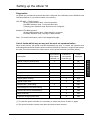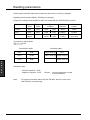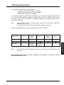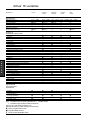
1
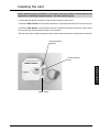
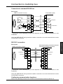
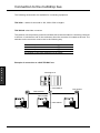
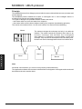
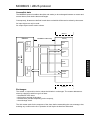
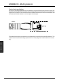
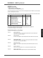
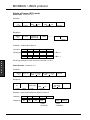
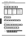
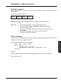
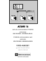
C 16 carte de communication PCMCIA protocoles UNI-TELWAY, MODBUS/JBUS PCMCIA communication card protocols UNI-TELWAY, MODBUS/JBUS VW3-A66301 guide d'exploitation user's manual TE Altivar 16 Carte de communication PCMCIA ............................................................................. page 2 protocoles UNI-TELWAY, MODBUS / JBUS PCMCIA communication card .................................................................................. page 52 protocols UNI-TELWAY, MODBUS / JBUS 1 F R A N Ç A I S E N G L I S H E N G L I S H Although every care has been taken in the preparation of this document, Schneider Electric SA cannot guarantee the contents and cannot be held responsible for any errors it may contain or for any damage which may result from its use or application. NOTE The hardware, software and services described in this document may be changed or modified at any time, either from a technical point of view or in the way they are operated. Their description can in no way be considered contractual. 5 2 Contents Introduction 54 Installing the card 55 Connection to the multidrop bus 56 to 58 Communication principle 59 to 61 Setting up the Altivar 16 62 and 63 Reading parameters 64 Writing parameters 65 Altivar 16 variables 66 to 84 UNI-TELWAY requests 85 to 88 MODBUS / JBUS protocol Diagnostics 89 to 100 101 E N G L I S H 5 3 Introduction The communication card, reference VW3-A66301, is designed to be used with Altivar 16 speed controllers which are fitted with a VW3-A16303 communication interface. It is designed to integrate these power switching components into modern control system architectures by enabling them to be connected to an industrial multidrop bus. Data exchanges enable all the functions of the Altivar 16 to be used : • • • • • function configuration, downloading of settings, control and supervision, monitoring, diagnostics. The VW3-A66301 communication card (PCMCIA type 3 format) has a 3 m connection cable fitted with a 15-pin SUB-D connector. The card manages the following communication protocols : • UNI-TELWAY, • MODBUS/J BUS. Only VW3-A16303 communication interface with software version above or equal to V1.3 IE04 can be used with VW3-A66301 PCMCIA communication card. E N G L I S H 5 4 Installing the card Before performing any operation on the speed controller switch it off and wait for the capacitors to discharge (approximately 1 min after switching off). • Check that the speed controller is connected to earth via terminal G. • Install the VW3-A16303 communication interface on the speed controller (see user's manual). • Insert the VW3-A66301 communication card in its guide so that the connection cable, which is 3 meters long, falls towards the base of the product. • Run the connection cable through the cable clamp located below the communication card slot. Communication interface Communication card E N G L I S H Cable clamp 5 5 Connection to the multidrop bus SUB-D connector pinout The RS 485 and RS 422 (RS 232 C compatible) standard transmission interface is electrically isolated from the speed controller. It is available on a 15-pin SUB-D connector. 5V 4,7 kΩ TX OV D (B) E 14 D (A) 7 8 4,7 kΩ & enable transmission 5 15 7 0V 6 15 14 13 5 12 4 11 5V 100 kΩ RX 3 10 2 3 RD (B) & 0V 1 9 8 RD (A) 100 kΩ 2 Seen from external contact side 0V Connection to the standard RS 485 bus Pins to use E N G L I S H Automated system SUB-D connector (15-pin) * PG PG 0V 15 0V D(B) 14 RXD+ Reception Transmission E Zt D(A) RX 7 RXD- TXD+ R TXD- 0V Reception A' B' 120 Ω R 1 nF A B E Transmission Zt line terminator recommended at both ends of the line * Connection of the shielding to both ends depends on installation constraints Recommendations • use a shielded cable with 2 pairs of twisted conductors, • connect the reference potentials to each other, • maximum length of the line : 1000 meters, • maximum length of a tap-link : 20 meters, • do not connect more than 28 stations on a bus, • cable routing : keep the bus away from the power cables (30 cm minimum), and make right-angle crossovers if necessary; connect the cable shielding to the earth of each device, • fit a line terminator at both ends of the line. 5 6 Connection to multidrop bus Connection to standard RS 422 bus Pins to use SUB-D connector (15-pin) Transmission TXD+ Automated system 0V 15 A 14 0V A' E TXDRXD+ B Rp A 3 RXD- E 8 B 5V * PG Reception TXD+ Zt Rp B' 0V RXDReception B' 0V A' R 7 RXD+ R Zt Transmission TXD- PG * Connection of the shielding to both ends depends on the electrical constraints on the installation. Using the ABE-6SD15F wiring interface enables connection to a screw terminal block via the 15-pin SUB-D connector. RS 232 C connection Pins to use Automated system (connection example using 25-pin SUB-D connector) SUB-D connector (15-pin) * PG 1 PG Transmission TXD 7 2 TXD Transmission Reception RXD 8 3 RXD Reception 0V SG 3 7 SG 14 4 RTS 2 5 CTS 15 6 DSR 5 20 DTR * Connection of the shielding to both ends depends on the electrical constraints on the installation. Using the ABE-6SD15F wiring interface enables connection to a screw terminal block via the 15-pin SUB-D connector. Configuring communication functions Refer to the operating manual of the PCMCIA communication interface of Altivar 16. 5 7 E N G L I S H Connection to the multidrop bus The following accessories are available for connecting equipment. TSX-CSA… cables for bus sold in 100, 200 or 500 m lengths. TSX-SCA62 subscriber connector This passive unit comprises a printed circuit fitted with screw terminals for connecting 2 devices to the bus. It includes an end of line terminator when the connector is located at the end. The switches on the connector must be set in the following way switch number switch position 2 OFF 3 OFF 5 OFF the position of the other switches has no effect. Example of connection to a UNI-TELWAY bus E N G L I S H TSX-SCM 21.6 TSX-CSB015 TSX-CSAXXX VW3-A16303 VW3-A66301 ATV-16 5 8 TSX-SCA62 Communication principle Connecting the speed controller The Altivar 16 can be connected according to the diagrams shown in the catalogue. The communication function provides the facility of remote control of the speed controller safety relay (contacts brought out to terminals SA-SC-SB). Using these contacts in the control circuit of the line contactor enables the power to be switched on and off remotely. Note : Since the power and control supplies are the same, power-up through the serial link isn't possible. Therefore, the line contactor release stops the communication. Nevertheless, the safety function of the relay is maintained, and continues to have priority over the remote control facility : the contact will open if a speed controller fault occurs. Status of the Altivar 16 The following diagram shows the three stable states of the speed controller. ➀ FAULT ➁ RESET CORRECTABLE FAULT ZERO FAULT "LOCKING" FAULT "LOCKING" FAULT ➂ UNCORRECTABLE FAULT 1 ZERO FAULT : in this state the safety relay is closed. 2 CORRECTABLE FAULT : this state is the result of the appearance of a type of fault which may disappear on its own (motor overheating, for example). This type of fault causes the speed controller safety relay to open. When the fault has disappeared, if contacts SA-SC, SC-SB are not used in the speed controller supply sequence, the Altivar 16 reset command (bit 0 of word W3050) acknowledges the fault and re-energizes the safety relay. 3 UNCORRECTABLE FAULT : this state is reached as soon as a serious or "locking" fault, which requires corrective action, occurs (overcurrent due to a short-circuit, for example). The safety relay can only be reset by a speed controller switch-on sequence. When a communication fault occurs, the speed controller can change to 2 states depending on its configuration : - Changing from line mode to local mode via an application-specific card logic input : the speed controller changes from the line frequency to the frequency required at the analog inputs with the acceleration or deceleration ramp. - Changing from local mode to line mode : the speed controller brakes on the deceleration ramp and takes the speed and operating direction required by the serial link. 5 9 E N G L I S H Communication principle Data structure The adjustment, control, supervision and monitoring of the Altivar 16 are performed using data (or objects) which are specific to the product. The data essentially comprises : • BITS : named Bi (i = bit number) which are used to execute logic commands. Example : B5 = start / stop command. • WORDS (of 16 bits) : named Wi (i = word number) which are used for storage, either of complete digital values (- 32768 to + 32767), or of 16 independent logic states (in which case these words are termed registers). Examples : W3051 = frequency reference (digital value), W3069 = fault register (16 fault bits). Notation : W3069,2 designates the bit in row 2 of register W3069. Access to data The following tables give the list of parameters which can be accessed via the communication link. The exact function of each parameter and its effect on the behavior of the speed controller are described in the user's manual and catalogue for the speed controller. Some data can be accessed in both read and write : these are the bits and words corresponding to adjustments, references and commands. This data is used by the speed controller. E N G L I S H However, data produced by the speed controller can only be accessed in read : signalling or fault data, etc. If written, they have no meaning and are rejected. 6 0 Communication principle Units These words are always expressed as signed numeric integer values (-32768 to +32767). The unit is defined for each of them. Example : W3052 : frequency reference, unit = 0.1 Hz, W3052 = 455 corresponds to a frequency reference of + 45.5 Hz. Range The range permitted by the speed controller is specified for each of the parameters. A value which is outside limits is always accepted, but will be automatically adjusted by the speed controller to either its lower or upper limit. Example : W3029 : slip compensation, range = 0.... 5 Hz. Any negative value is adjusted to 0 (0 Hz). Any value above 50 is adjusted to 50 (5 Hz). Values on switching on Each time it is switched on, the Altivar 16 is initialized with the configuration and the adjustments stored in the EEPROM memory. The speed controller is systematically placed in LOCAL control mode (orders are expected on its terminal block). To control it via the multidrop bus, its commands must be assigned to LINE mode : command word W3050 is written by setting bits DLI and FLI to 1. E N G L I S H Altivar 16 variables Some Altivar 16 variables can be accessed at two different addresses : • in the 3000 to 3078 address zone reserved for the Altivar 16, • in the 0 to 127 address zone already used by the Altivar 45 2. While the control system is operating (control, monitoring or modification of the speed controller adjustments), only one zone should be used. 1– Address zone reserved for the Altivar 16 (3000 to 3078) This address zone contains all the speed controller parameters for optimum use of the facilities of the Altivar 16. 2– Address zone (0 to 127) common to the Altivar 16 and the Altivar 45 2 This address zone should only be used when integrating an Altivar 16 in a control system which until now has only included Altivar 45 2 controllers. Not all Altivar 16 parameters appear here, in particular those connected with functions which require reconfiguration of the applicationspecific card. In certain cases, using these addresses avoids the necessity of modifying the program. Small differences in relation to the Altivar 45 2 are shown in the comments. 6 1 Setting up the Altivar 16 Configuring communication The following parameters can be set using the terminal : • Pro : defines the communication protocol : - UtL : UNI-TELWAY - ASC : Modbus ASCII - rtu : Modbus RTU / JBUS - FIP : FIPIO • bdr: defines the data rate in kbps. Possible values : 0.3 / 0.6 / 1.2 / 2.4 / 4.8 / 9.6 / 19.2 • For : format of the data frame 8 0 1 1 : 1 stop 2 : 2 stops 0 : odd parity E : even parity n : no parity 8 : 8 data bits 7 : 7 data bits • Adr : Logic address of the speed controller E N G L I S H 6 2 UtL rTu ASC bdr All values All values All values For 8.0.1 8.0.7 / 8.E.1 8.n.7 / 8.n.2 8.0.7 / 8.E.1 8.n.1 / 8.n.2 7.0.1 / 7.E.1 7.0.2 / 7.E.2 Adr 1 to 31 1 to 31 1 to 31 FIP 1 to 63 Setting up the Altivar 16 Diagnostics On power-up, and after the protocol has been configured, the COM lamp on the PCMCIA card indicates whether or not communication is functioning. UNI-TELWAY - FIPIO protocol : Green COM indicator lamp : Normal operation Red ERR indicator lamp : Communication fault Flashing green indicator lamp: Serial link not configured. Modbus RTU/JBUS protocol : Green COM indicator lamp : Data transfer in progress. Red ERR indicator lamp : Waiting for data transfer Note : For further information, refer to the diagnostics page. List of faults which may or may not be reset via communication When a fault occurs, the speed controller freewheels to a stop. To restart, the operator must acknowlege the fault and reset the speed controller (W3050.0). However, 2 types of fault cannot be reset via communication but require action on the speed controller (see table below) : Description Speed controller internal fault Not possible to reset speed controller (1) Possible to reset speed controller (2) X Communication fault Code displayed INF X SLF External fault X SRF Supply too low X USF Supply too high X OSF Supply phase missing X PnF EEPROM memory fault X Speed control fault Overcurrent - overheating Overvoltage due to harsh braking E N G L I S H EEF X X SPF DRF X OBF Overcurrent due to harsh braking X OBF Motor overload X OLF Capacitor charging relay fault X CRF (1) To reset the speed controller it is necessary to switch the power off then on again. (2) The speed controller can be reset after the fault has been cleared. 6 3 Reading parameters All the speed controller data can be read when the motor is running or stopped. Signalling words (words W3060 - W3078) are read-only. Example of reading words W3020 to 3043 (24 words) with the UNI-TELWAY protocol. Description Request Code Category Code Type of object Object address Object number Format byte byte byte byte Word Word Code H'36' H'07' H'68' H'07' H'OBCC' H'0018' Comments read object internal words specific byte (3020 in hex) Number of words (24 in hex) Text block for transmission TxTi, C = H'0736' TxTi, L = 4 Transmission table E N G L I S H Reception table H'07' H'68' W3020 least sig. H'07' H'CC' H'OB' W3021 least sig. W3020 most sig. H'18' H'00' W3021 most sig. Response code : - Positive response : H'FE' - Negative response : H'FD' Note : 6 4 Reason : incorrect parameter number or wrong address For further information about the UNI-TELWAY protocol, refer to the UNI-TELWAY requests page. Writing parameters It is possible to write Altivar 16 parameters for : - command words (motor running or stopped), - adjustment words (motor running or stopped), - configuration words (motor stopped). To control the speed controller from the multidrop bus, it is necessary to execute commands on line : command word W3050 is written by setting bits DLI and FLI to 1. Bits DLI and FLI of the command register offer the possibility of partially assigning the commands which can be executed from the bus. Note : setting bit NTO to 1 in the command register inhibits the communication fault check (Altivar 16 "SLF" fault). For safety reasons, care must be taken when using this command. Setting word W3050 to the value 5 with Modbus protocol (RTU frame) Description Format Code Function Code Word no. Value of the word CR16 1 byte 1 byte 2 bytes 2 bytes 2 bytes 01 Comment Note : Slave no. 06 Writing a word OB EA 00 05 6A 19 3050 in Hex. = OBEA For further information on Modbus frames, see the end of this guide (Modbus / Jbus Protocol). The following table shows all the functions of the Altivar 16 with its various application-specific cards. 6 5 E N G L I S H Altivar 16 variables Applications Drive functions Maximum frequency Voltage/frequency ratio selection (1) Slip compensation Switching frequency Current limit Braking to a standstill by DC injection (f<0.1 Hz) E N G L I S H ATV16 General usage Materials handling Variable torque High speed ▲ 40 ... 200Hz ■ n-P-L ■ yes/no ■ 5/10kHz ●1.5 In ▲40 ... 200Hz ■ n-L ■ yes/no ■ 5/10kHz ▲0.5 to 1.5 In ▲40 ... 200 Hz ■ n-L ■ yes/no ● 5kHz ●1.5 In ▲40 ... 70/80Hz ●P no ■ 5/10kHz ●1.2 In ▲40 ... 400Hz ■ n-L no ● 5kHz ●1.2 In ■ yes/no ■ yes/no no no ■ yes/no ■ ■ ■ ■ ■ ■ ■ ■ ■ ■ ■ ■ Functions in the application-specific cards • ± 10 V analog input Summing Speed regulation PI controller • Logic inputs 2nd ramps Preset speeds Current limit +/- speed Step by step operation (JOG) Fast stop Freewheel stop DC injection Automatic/manual Start/stop Reset after fault Change motor power Speed controller forced in local mode (3) • Logic outputs Brake control sequence Speed reference reached Low speed reached High speed reached Current limit reached 1.1 In overload reached 100% thermal state reached ■ ■ ■ ■ ■ ■ ■ ■ ■ ■ ■ ■ ■ ■ ■ ■ ■ ■ ■ ■ ■ ■ ■ ■ ▲ ■ ■ ■ ■ ■ ■ • Analog output Motor frequency Motor current ■ ■ ■ ■ ■ ■ ■ ■ ■ ■ ■ ■ ■ ■ Preprogrammed and programmable characteristics – S ramps – Skip frequencies – Controlled stop on AC supply break (2) – Automatic catching a spinning load – Automatic restart ■ ■ ■ ■ ■ ■ ■ ■ (1) n : constant torque (normal applications), P : variable torque, L : constant torque (heavily-loaded machines). (2) ATV16 U..N4 speed controller only. (3) Only the Altivar 16 with software version IE07. ● - fixed, programmed function ■ - programmable function ▲ - function with adjustable value 6 6 ■ ■ ■ ■ ■ ■ Altivar 16 variables Address zone reserved for Altivar 16 Configuration words (read and write) (write when motor is stopped) WORD NAME RANGE UNIT DESCRIPTION POSSIBLE VALUES W3000 LI1 0…10 Assignment of logic input LI1 0 = not assigned 1 = start/stop 2 = fast stop 3 = fault reset 4 = + speed 5 = freewheel stop 6 = switching to ramp 2 7 = reduction of current limit 8 = Jog 9 = change motor power 10 = local forcing W3001 LI2 0…11 Assignment of logic input LI2 0 = not assigned 1 = 3rd speed 2 = fast stop 3 = fault reset 4 = - speed 5 = freewheel stop 6 = automatic / manual switching 7 = switching to ramp 2 8 = reduction of current limit 9 = Jog 10 = change motor power 11 = local forcing W3002 LI3 0…10 Assignment of logic input LI3 W3003 AI1 0…5 Assignment of analog input AI1 E N G L I S H 0 = not assigned 1 = 4th speed 2 = fast stop 3 = DC injection 4 = fault reset 5 = freewheel stop 6 = switching to ramp 2 7 = reduction of current limit 8 = Jog 9 = change motor power 10 = local forcing 0 = not assigned 1 = speed feedback 2 = speed feedback + backdriving control 3 = summing reference 2 input 4 = PI feedback 5 = manual reference input 6 7 Altivar 16 variables Address zone reserved for Altivar 16 Configuration words (read and write) (write when motor is stopped) WORD NAME E N G L I S H DESCRIPTION POSSIBLE VALUES W3004 LO1 0…6 Assignment of logic output LO 0 = not assigned 1 = 100% thermal state reached 2 = frequency reference reached 3 = current limit reached 4 = LSP reached 5 = HSP reached 6 = 1.1 Ith overload reached W3005 SAB 0…4 Assignment of relay S2A S2B 0 = not assigned 1 = 100% thermal state reached 2 = frequency reference reached 3 = HSP reached 4 = brake control W3006 AO1 0…2 Assignment of analog output AO 0 = not assigned 1 = motor frequency 2 = motor current W3007 CPM 0…4 Motor power coefficient 0 = coefficient 1/1 1 = coefficient 1/2 2 = coefficient 1/3 3 = coefficient 1/4 4 = coefficient 1/5 W3008 0…3 Type of DC injection 0 = no injection 1 = injection for f < 0.1 Hz 2 = injection for f < LSP 3 = injection for f < SRF TIC W3009 TFR W3010 UNS W3011 FRS W3012 UFT 6 8 RANGE UNIT 40…400 Hz 0.1 Hz Maximum frequency 0…7 Motor nominal voltage 0 = 208 V 1 = 220 V 2 = 230 V 3 = 240 V 4 = 380 V 5 = 400 V 6 = 415 V 7 = 460 V 40…400 Hz 0.1 Hz Motor nominal frequency 0…2 Type of voltage/ frequency ratio 0 = linear N 1 = quadratic P 2 = linear L Altivar 16 variables Address zone reserved for Altivar 16 Configuration words (read and write) (write when motor is stopped) WORD NAME RANGE UNIT DESCRIPTION W3013 CF1 Specific functions configuration register RPS W3013,1 S ramp POSSIBLE VALUES W3013,0 Reserved 0 = linear 1=S FLR W3013,2 Flying restart 0 = no 1 = yes ATR W3013,3 Automatic restart 0 = no 1 = yes SFR W3013,4 10 kHz switching frequency 0 = 5 kHz 1 = 10 kHz W3013,5 Reserved STP W3013,6 Controlled stop on AC supply break 0 = no 1 = yes BRA W3013,7 Adaptation of the deceleration ramp 0 = no 1 = yes 1 = yes SLP W3013,8 Slip compensation 0 = no RBL W3013,9 Activation of the + / – speed reference 0 = no 1 = yes SCE W3013,A Speed ref. in EEPROM memory 0 = no 1 = yes W3013,B Inhibit boost at start-up 0 = no 1 = yes BST W3013,C Reserved W3013,D Reserved W3013,E Reserved W3013,F Reserved E N G L I S H W3014 to W3019 : Reserved 6 9 Altivar 16 variables Address zone reserved for Altivar 16 Adjustment words (read and write) E N G L I S H WORD NAME RANGE UNIT DESCRIPTION W3020 LSP 0…HSP 0.1 Hz Low speed W3021 HSP LSP…TFR 0.1 Hz High speed W3022 ACC 0.1…600s 0.1 s Acceleration time W3023 DEC 0.1…600s 01s Deceleration time W3024 FLG 0…100 1 Frequency loop gain (if FLG=100 : frequency loop inhibited) W3025 UFR 0…100 1 Set voltage / frequency ratio W3026 ITH 0.5…1.15 In 0.1 A W3027 IDC 0.5…1.5 Ith 0.1 A DC current amplitude W3028 TDC 0…5.1 s 0.1s DC injection time (if TDC= 5.1s : continuous DC injection) W3029 CGL 0…5 Hz 0.1 Hz W3030 AC2 0.1…600 s 0.1 s Acceleration time 2 W3031 DE2 0.1…600 s 0.1 s Deceleration time 2 W3032 JOG 0.1…10 Hz 0.1 Hz W3033 SP3 LSP…HSP 0.1 Hz 3rd speed W3034 SP4 LSP…HSP 0.1 Hz 4th speed W3035 JF1 0…TFR 0.1 Hz Skip frequency 1 W3036 JF2 0…TFR 0.1 Hz W3037 RGP 0…100 0.1 PI controller proportional gain W3038 RGI 0…100 0.1 PI controller integral gain W3039 IBR 0…1.15 ln 0.12 A Brake control level W3040 SMF 0…LSP 0.1 Hz Brake application level W3041 SRF 0…LSP 0.1 Hz Brake release level W3042 TMF 0…5 s 0.1 s Brake application time W3043 LTI 0.5…1.5 ln 0.1 A Current limit level W3044 to W3049 : Reserved 7 0 Thermal current Slip compensation JOG speed Skip frequency 2 Altivar 16 variables Address zone reserved for Altivar 16 Command words (read and write) WORD NAME RANGE W3050 COM UNIT DESCRIPTION Command register RST W3050,0 Reset speed controller DLI W3050,1 Assign commands on line FLI W3050,2 Assign frequency reference on line (1) W3050,3 Reserved NTO W3050,4 Communication check inhibited (2) RUN W3050,5 Start / stop command (1) DCB W3050,6 DC injection braking command W3050,7 Reserved CAL W3050,8 Select freewheel stop CAR W3050,9 Select fast stop W3050,A Reserved W3050,B Reserved W3050,C Reserved W3050,D Reserved EFL W3050,E External fault command E N G L I S H W3050,F Store in EEPROM (3) W3051 FRH W3052 LOL LSP…HSP Signed line frequency reference Write logic outputs on line (only if they are not assigned) W3053,0 Value applied at S2A-S2B W3053,1 Value applied at LO W3053,2 to F Reserved W3053 AOL 0…255 Write analog output AO on line (only if Al not assigned) W3054 to W5059 : Reserved The bits are active at state 1 (1) The same message should not be used to assign FLI and RUN. Use 2 messages, the 1st for FLI, the 2nd for RUN. (2) The Altivar 16 changes to fault condition SLF : • in UNI-TELWAY when there has been no polling for 10 s, • in MODBUS if more than 10 s elapse between requests. Setting this bit to 1 inhibits this check. For safety reasons, this should only be performed during debugging phases. (3) Global command to store all the adjustments and the entire configuration in the speed controller EEPROM. The storage takes a few seconds, and access to the speed controller is refused while it is being performed. For this function, the speed controller must be on line and the motor stopped. 7 1 Altivar 16 variables Address zone reserved for Altivar 16 Signalling words (read only) WORD NAME W3060 RANGE UNIT DESCRIPTION STR LOC Speed controller status register W3060,0 All commands in local mode RDY W3060,1 Speed controller ready (RDY or SLC) FAI W3060,2 Faulty REN W3060,3 Reset authorized (following correctable fault) POSSIBLE VALUES W3060,4 Reserved E N G L I S H FLO W3060,5 Speed controller forced in Local mode NTO W3060,6 Communication check inhibited CFA W3060,7 Correctable fault RNG W3060,8 Motor running RVE W3060,9 Direction of rotation BRE W3060,A DC injection braking SST W3060,B Steady state OVL W3060,C Motor thermal overload alarm OBR W3060,D Overbraking alarm LIM W3060,E Current limit W3060,F Reserved W3061 FRR 0.1 Hz Actual rotation frequency (signed value) W3062 LCR 0.1 A Motor current W3063 ULN 0.1 V Mains supply voltage W3064 IOL W3065 AIV 0…10000 W3066 IAI -10000…+10000 W3067 IAO 0…255 W3068 FRE 7 2 Speed controller logic I/O status register W3064,0 FW input state W3064,1 RV input state W3064,2 Ll1 input state W3064,3 Ll2 input state W3064,4 Ll3 input state W3064 5 S2A-S2B output state W3064 6 LO output state W3064,7 to W3064,F Reserved AIV or AIC analog input value Al analog input value AO output value 0.1 Hz Effective frequency reference (signed value) 0 = forward 1 = reverse 1= thermal state ≥100% Altivar 16 variables Address zone reserved for Altivar 16 Signalling words (read only) WORD NAME RANGE UNIT DESCRIPTION W3069 FLT Fault register : fault which has caused speed controller to stop INF W3069,0 Speed controller internal fault (*) SLF W3069,1 Communication fault EEF W3069,2 Storage fault in EEPROM SRF W3069,3 External fault (generated by an EFL command) USF W3069,4 Mains supply undervoltage OSF W3069,5 Mains supply overvoltage PHF W3069,6 Supply phase(s) failure POSSIBLE VALUES W3069,7 Reserved W3069,8 Speed regulation fault / tachogenerator absent DRF W3069,9 Overcurrent, PWM overheating (*) OBF W3069,A Overvoltage caused by overbraking OBF. W3069,B Overcurrent caused by overbraking OLF W3069 C Motor overload W3069,D Reserved W3069,E Reserved W3070 CRF W3069,F Capacitor charging relay fault DPR Register of current faults INF W3070,0 Speed controller internal fault SLF W3070,1 Communication fault EEF W3070,2 Storage fault in EEPROM SRF W3070,3 External fault (generated by an EFL command) USF W3070,4 Mains supply undervoltage OSF W3070,5 Mains supply overvoltage PHF W3070,6 Supply phase(s) failure E N G L I S H W3070,7 Reserved W3070,8 Speed regulation fault / tachogenerator absent DRF W3070,9 Overcurrent OBF W3070,A Overvoltage caused by overbraking OBF. W3070,B Overcurrent caused by overbraking OLF W3070,C Motor overload W3070,D Reserved W3070,E Reserved CRF W3070,F Capacitor charging relay fault (*) These faults are uncorrectable and cannot be acknowledged by the communication link. 7 3 Altivar 16 variables Address zone reserved for Altivar 16 Signalling words (read only) WORD NAME RANGE UNIT DESCRIPTION POSSIBLE VALUES W3071 DP1 Past fault 1 each of these words W3072 DP2 Past fault 2 has the same structure W3073 DP3 Past fault 3 as W3069 W3074 DP4 Past fault 4 W3075 DP5 Past fault 5 W3076 DP6 Past fault 6 W3077 DP7 Past fault 7 W3078 DP8 Past fault 8 E N G L I S H 7 4 Altivar 16 variables Address zone common to Altivar 16 and Altivar 45 2 Control bits (read and write) BIT NAME DESCRIPTION FUNCTION B0 TST De-energization of speed controller safety relay Disconnects the Altivar 16 power supply if the contact of the relay is used for the hold-in circuit of the line contactor B1 (*) RST Fault reset (Speed controller reset) Acknowledges a correctable fault which has disappeared and resets the safety relay B2 (*) CLO Assignment of control to LOCAL mode The Altivar 16 can only be controlled via its terminals (logic and analog inputs) B3 (*) CLI Assignment of control to LINE mode The Altivar 16 is controlled via the multidrop bus B4 NTO Inhibition of communication check The Altivar 16 changes to fault condition SLF : • in UNI-TELWAY after no polling for 10 s • in MODBUS if more than 10 s elapse between two requests Setting this bit to 1 inhibits this check. For safety reasons this feature should only be used during debugging phases B5 RUN Start / stop command 1 = start 0 = stop B6 REV Frequency reference sign 1 = negative 0 = positive The direction of rotation can be reversed by changing the state of this bit or by providing a frequency reference of opposite sign in word W19 B7 DCB Braking control Takes priority over the RUN bit B8 CAL Selection of a freewheel stop Active when there is a stop command B9 CAR Selection of a fast stop Active when there is a stop command B10 E N G L I S H Reserved (*) These bits initiate the action shown when they are written as 1. They are reset to zero by the speed controller. If they are written as zero they have no effect and are always read as zero. 7 5 Altivar 16 variables Address zone common to Altivar 16 and Altivar 45 2 Adjustment words (read and write) WORD NAME RANGE UNIT W0 – – – Reserved W1 – – – Reserved W2 CGL [0... 5Hz] W3 E N G L I S H DESCRIPTION 0.1Hz Slip compensation – Not used W4 – – – Not used W5 – – – Not used W6 – – – Not used W7 IDC [0.5... 1.5Ifh] 0.1A DC amplitude when stopping W8 TDC [0... 4s] 0.1s DC injection time when stopping W9 UFR [0... 100] 1 With ATV 45 2 range coefficient from 0 to 99 ITH [0.45... 1.05In] 0.1A Motor thermal current W11 FLG [0... 99%] 1% Frequency loop gain – – Not used – Not used W13 – – – With ATV 45 2 range from 0.5 to 1.5 In Voltage/frequency ratio adjustment W10 W12 COMMENTS With ATV 45 2 range from 0 to 100 W14 LSP [0...HSP] 0.1Hz Low speed W15 HSP [LSP... TFR] 0.1Hz High speed W16 ACC [0.1... 600s] 0.1s Acceleration time With ATV 45 2 range from 0.2 to 990 s W17 DEC [0.1... 600s] 0.1s Deceleration time With ATV 45 2 range from 0.2 to 990 s 7 6 Adjust TFR in W3009 Altivar 16 variables Address zone common to Altivar 16 and Altivar 45 2 Command words (read and write) WORD NAME W18 COM RANGE UNIT – – DESCRIPTION COMMENTS Command register W18,0 (RST) Reset speed controller (fault reset) W18,1 (DLI) Assign logic commands See note 1 on LINE W18,2 (FLI) Frequency reference See notes 1 and 2 on LINE W18,3 Reserved W18,4 (NTO) Inhibit communication check W18,5 (RUN) Start / stop command See note 2 W18,6 (DCB) Braking control W18,7 Reserved W18,8 (CAL) Select freewheel stop E N G L I S H W18,9 (CAR) Select fast stop W18,A Not used W18,B Reserved W18,C Reserved W18,D Reserved W18,E Reserved W19 FRH [LSP... HSP] 0.1Hz W18,F Storage in EEPROM See note 3 Signed frequency reference Signed value The bits are active at state 1. note 1 : Bits W18,1 and W18,2 can be used to partially assign commands which can be executed from the multidrop bus. It is important to set them correctly each time the COM register is written. note 2 : Do not use the same message to assign FLI and RUN. Use 2 messages : the 1st for FLI, the 2nd for RUN. note 3 : Global command to store all the adjustments (W0 to W17) and the entire configuration (W33 to W66) in the speed controller EEPROM. This command should be used with care : the storage takes a few seconds, and access to the speed controller is refused while it is being performed. 7 7 Altivar 16 variables Address zone common to Altivar 16 and Altivar 45 2 Signalling words (read only) WORD NAME W20 STR RANGE – UNIT DESCRIPTION COMMENTS Status register W20,0 (LOC) All commands assigned in LOCAL mode W20,1 (RDY) Speed controller ready W20,2 (FAI) Faulty W20,3 (REN) Reset authorized W20,4 Not used W20,5 (FLO) Speed controller forced in LOCAL mode W20,6 (NTO) Communication check inhibited W20,7 (CFA) Correctable fault E N G L I S H W20,8 (RNG) Running Motor rotating W20,9 (RVE) Direction of operation 0 = forward 1 = reverse W20,A (BRE) DC injection braking W20,B (SST) Steady state W20,C (OVL) Motor thermal overload alarm W20,D (OBR) Overbraking alarm W20,E (LIM) Current limit W20,F Not used 7 8 Altivar 16 variables Address zone common to Altivar 16 and Altivar 45 2 Signalling words (read only) WORD NAME W21 FLT RANGE UNIT – DESCRIPTION COMMENTS Fault register W21,0 (INF) Speed contr. internal fault (*) W21,1 (SLF) Communication fault W21,2 (EEF) EEPROM fault W21,3 (SRF) Fault generated by the TST command W21,4 (USF) Mains supply undervoltage W21,5 (OSF) Mains supply overvoltage W21,6 (PHF) Supply phase(s) failure W21,7 Not used W21,8 (SPF) Speed regulation fault W21,9 (DRF) Overcurrent, PWM overheating, With ATV 45 2, this bit underheating of PWM control (*) indicates an overcurrent E N G L I S H W21,A (OBF) Overvoltage caused by overbraking W21,B (OBF.) Overcurrent caused by overbraking W21,C (OLF) Motor overload W21,D Not used W21,E Reserved W21,F (CRF) Charging relay fault W22 LCR 0.1A Motor current W23 RFR 0.1Hz Actual rotation frequency W24 – – W25 ULN 1V W26 – – Not used W27 – – Reserved W28 – – Reserved Signed value Not used Mains voltage (*) These faults are uncorrectable and cannot be acknowledged by the communication link. 7 9 Altivar 16 variables Address zone common to Altivar 16 and Altivar 45 2 Signalling words (read only) WORD NAME W29 RANGE DIN UNIT DESCRIPTION – Speed controller logic input COMMENTS status register W29,0 FW input W29,1 RV input W29,2 Not used W29,3 Not used W29,4 Not used W29,5 to W29,F : reserved W30 DAI [0... 1000] Value of speed controller 0 = 0V or 0 mA or 4 mA analog input 1000 = 10V or 20 mA W31 – – Reserved W32 – – Reserved E N G L I S H 8 0 Altivar 16 variables Address zone common to Altivar 16 and Altivar 45 2 Configuration Configuration words can only be written when the speed controller is stopped They are stored in the EEPROM memory via the COM command register (bit W18,F). Configuration words (read and write) (write when motor is stopped) WORD NAME RANGE UNIT DESCRIPTION W33 – – Not used W34 – – Not used W35 – – Configuration register POSSIBLE VALUES W35,0 Not used W35,1 Not used W35,2 Not used W35,3 Not used W35,4 (SLP) Slip compensation 0 = no and 1 = yes W35,5 Not used E N G L I S H W35,6 Not used W35,7 Not used W35,8 Not used W35,9 Not used W35,A Not used W35,B Not used W35,C Not used W35,D Not used W35,E Not used W35,F Not used 8 1 Altivar 16 variables Address zone common to Altivar 16 and Altivar 45 2 Configuration words (read and write) (write when motor is stopped) WORD NAME W36 – RANGE – UNIT DESCRIPTION POSSIBLE VALUES Configuration register 2 W36,0 (FLR) Flying restart (automatic catching a spinning load) 0 = no and 1 = yes W36,1 Not used W36,2 Not used W36,3 (ATR) Automatic restart 0 = no and 1 = yes W36,4 to W36,F : not used W37 – Not used W38 – Not used W39 – Not used W40 – Not used W41 E N G L I S H RPS 0...1 Ramp shapes (1) W42 – Not used W43 – Not used W44 – 0 = linear 1 = S Not used W45 BRA 0...1 Deceleration ramp adaptation 0 = no 1 = yes W46 UFT 0...2 Voltage/frequency ratio (2) 0 = linear N 1 = quadratic P 2 = linear L (1) Parabolic ramp not available on the Altivar 16 (2) The F type does not exist on the Altivar 16 8 2 Altivar 16 variables Address zone common to Altivar 16 and Altivar 45 2 Configuration words (read and write) (write when motor is stopped) WORD NAME RANGE UNIT DESCRIPTION W47 – – Not used W48 – – Not used W49 – – Not used W50 – – Not used W51 – – Not used W52 IBR W53 AC2 0...In 0.1...600 s 0.1 A Brake control level 0.1 s Acceleration time 2 COMMENTS on the ATV 45 2 : adjustable from 0.2 to 990 s W54 DE2 0.1...600 s 0.1 s Deceleration time 2 W55 – – Not used W56 – – Not used on the ATV 45 2 : adjustable from 0.2 to 990 s E N G L I S H 8 3 Altivar 16 variables Address zone common to Altivar 16 and Altivar 45 2 Configuration words (read and write) (write when motor is stopped) WORD NAME RANGE UNIT DESCRIPTION W57 – – Not used W58 – – Not used W59 – – Not used W60 – – Not used W61 – 0...LSP 0.1Hz Brake application level W62 – 0...LSP 0.1 s Brake release level W63 – 0...5 s 0.1 s Brake application time COMMENTS adjustable from 0 to 4 s W64 – – Not used W65 – – Not used W66 – 40...200 Hz 0.1 s Nominal frequency W61 to W119 : Reserved E N G L I S H Maintenance The following words can be used for diagnostics and maintenance. They contain a list of the 8 most recent faults which have caused the speed controller to stop (power cuts are not considered as faults). These 8 words are managed on a stacking principle : the appearance of a fault causes the stack to move downwards and the fault which has appeared is stored in the 1st W120 word. This principle continues to be used when the stack is full. These words cannot be modified or reset to zero. Words for maintenance (read only) 8 4 WORD NAME W120 W121 . . to . . W127 DP1 DP2 DP8 DESCRIPTION COMMENTS Register of the most recent fault Each of these words has the same format as the FLT signalling register [W21] etc. The value 0 indicates that there is no fault Register of the eighth fault recorded UNI-TELWAY requests General The exchange of data between computer systems, PLCs and other intelligent systems must be performed using a common language. This language should be as simple as possible and understood by everyone involved. Nevertheless, it must be possible to check every exchange to ensure the integrity of the transfers. The variables exchanged are therefore inserted in a frame which generally comprises the following : Heading Address Request Data Check End Each protocol defines the presence, the format and the contents of the various groups of variables which surround the data zone. This structuring makes it possible to define the start and the size of messages, if necessary the system to which the data is addressed, the type of function required, the variables themselves, a control parameter and an end code which validates the whole message. The form and content of this frame are different for each type of protocol. List of requests The following table describes the requests accepted by the Altivar 16 and their limits. Details of the coding of the requests are given in the UNI-TELWAY reference manual. Request Code (hex) Altivar 16 Identification Protocol version Status Mirror Read error counters Reset counters H’0F’ H’30' H’31' H’FA’ H’A2' H’A4' Yes Yes Yes Yes Yes Yes Read a bit Write a bit H’00' H’10' Yes Yes Read a word Write a word H’04' H'14' Yes Yes Read objects Write objects H’36' H’37' 63 words max. 60 words max. Event data – Yes 2 words Specific H’F2' See later E N G L I S H Identification request - Request code H'OF' Response given by Altivar Response code = H'3F' Product type = H'14' for Altivar Sub-type = H'16' Altivar 16 Product version = H'XX' software version (eg : H'21' for V2.1) ASCII string* = product reference (eg : ATV-16U29N4) * The first byte of an ASCII string always corresponds to the length of the string. 8 5 UNI-TELWAY requests Request status - Request code H'31' Response given by Altivar Response code = H'61' Current status = H'XX' bit 0 : internal fault bit 1 : correctable fault bit 2 : uncorrectable fault bit 3 : not significant bit 4 : not significant bit 5 : not significant bit 6 : speed controller stopped (RDY or SLC or fault) bit 7 : speed controller in LOCAL control Status mask = H'C7' indicates the significant bits for the current status UNI-TELWAY frame Heading Target address Transmitter address Length of message Category + request Data Check Requests to read and write objects These requests are used to access several words within the limits described on the previous page. These requests can be coded by specifying : Question code (TXTi,C) Category Segment Object type E N G L I S H = H’36' (read) or H’37' (write) = 0...7 = H’68' (internal word) = H’06' for a byte (8 bits) in reading or H’07' for a word (16 bits) in reading and writing = H’xxxx’ Object address Etc Words reserved or not used are read to 0 and their write is not significant. The response to a "write objects" request is accepted if a word is written at least. Example : programming on a TSX7 PLC using a text block. READ words W3020 to W3023 of the Altivar 16. – Using word type object = H’07' Transmission text block TxTi,C = H’0736' (category + request) TxTi,L = 6 + transmission table Transmission table Internal word segment Word type Reception text block TxTi,V = H’66' (confirm) TxTi,S = 9 (9 bytes received) + reception table Reception table W3020 (least sig.) H'07' W3021 (least sig.) W3020 (most sig.) H'07' H'68' 3020 4 W3022 (least sig.) W3021 (most sig.) W3023 (least sig.) W3022 (most sig.) W3023 (most sig.) 4 words to read Number of first word The data received in the reception table is offset by one byte. It is the application program which must correct the data (for example by successive offsets) before using it. 8 6 UNI-TELWAY requests – Using byte type object = H'06' Transmission text block TxTi,C = H'0736' (category + request) TxTi,L = 6 + transmission table Reception text block TxTi,V = H'66' (confirm) TxTi,S = 10 (10 bytes received) + reception table Transmission table Internal word segment Type of byte Reception table W3019 (most sig.) H'06' W3020 H'06' H'68' W3021 6039 9 W3022 W3023 9 bytes to read (most significant bit of W3019 + 8 bytes comprising W3020 to W3023) Number of first byte (most significant bit of W3019 has address 2 x 3019 + 1 = 6039) Reading the most significant bit W3019 can be used to obtain a correct framework of the following words in the reception table, and to avoid shifts between the most and least significant bits in these words. Event data The Altivar 16 transmits data on its own initiative to the UNI-TELWAY link master without having first received a question. This data is sent via the "unsolicited data" request and does not require a response from the receiver. Data is transmitted in the following 2 cases : – When a fault appears or disappears (rising or falling edge at status register bit W3060,2). – When the speed controller is forced into local control via one of its logic inputs, if that input has been assigned to this function (rising or falling edge at this input), or via the local key on the interface for the PCMCIA communication card. Size of event data : 2 words of 16 bits sent in the following order : – STR status register (word W3060). – FLT fault register (word W3069). To transmit unsolicited data, the Altivar 16 must have an address between 1 and 32. 8 7 E N G L I S H UNI-TELWAY requests Summary : the use of event data with a TSX PLC requires : – Correct configuration of the UNI-TELWAY link master module. – Regular monitoring of the indicators which display the arrival of unsolicited data and the addresses of the transmitters. – Acquisition of this data via the request to read event data. Specific control request This request is used to control the Altivar 16 and to obtain in return data essential for controlling the speed controller. Request format Request code Category Specific request code Reserved Command Reference Acceleration Deceleration : byte : byte : byte : byte : word : word : word : word = H'F2' = 0...7 =0 =0 = COM = FRH = ACC = DEC : byte : byte : byte : word : word : word : word = H'F2' = H’30' =0 = FRH = STR = FLT = LCR Confirm format Response code Specific response code Reserved Reference Status register Fault register Motor current E N G L I S H Negative response Response code : byte Cause : incorrect number of parameters 8 8 = H'FD' MODBUS / JBUS protocol MODBUS frames Note : In the rest of this document MODBUS and JBUS functions are grouped together under the heading MODBUS. Two transmission modes can be used, only one of them being used in a system. RTU mode The frame defined for the MODBUS protocol has neither message heading bytes nor end of message bytes. It is defined as follows : Address Request Data CRC16 The data is transmitted in binary code. CRC16 : cyclical redundancy check. The end of frame is detected on a silence of 3 characters or more. ASCII mode The frame is complete and is defined in the following way : Heading Address Request Data LRC End "CRLF" – heading = ":" (H’3A), – the data is coded in ASCII : each byte is divided into 2 four-bit bytes, each of which is coded by an ASCII character (0 to F), – LRC : longitudinal redundancy check, – end : "CR" "LF" (H’0D and H’0A). E N G L I S H 89 MODBUS / JBUS protocol Principle The MODBUS protocol is a dialogue protocol which creates a hierarchical structure (a master and several slaves). The MODBUS protocol enables the master to interrogate one or more intelligent slaves. A multidrop link connects the master and slaves. Two types of dialogue are possible between master and slaves : – the master talks to a slave and waits for a response, – the master talks to all the slaves without waiting for a response (broadcasting principle). The slaves are numbered from 1 to 255, and number 0 is reserved for broadcasting. Master The master manages the exchange and only it can take the initiative. The master repeats the question when there is an incorrect exchange, and declares the interrogated slave absent if no response is received within a given time envelope. Only one device can transmit on the line at any time. No slave can send a message itself unless it is invited to do so. Slave j E N G L I S H Slave i Slave k Note No lateral communication (ie. slave to slave) can be performed directly. The application software of the master must therefore be designed to interrogate a slave and send back data received to another slave. 90 MODBUS / JBUS protocol Accessible data The MODBUS protocol enables data (bits and words) to be exchanged between a master and several slaves, and checks these exchanges. Consequently, bit areas are defined in each slave unit which will be read or written by the master. An input object can only be read. An output object can be read or written. Slave i Transmission table Master MODBUS addressing Slave j Input bits User program Output bits Reception table Input words E N G L I S H Output words Slave k Exchanges The master, or supervision device, takes the initiative in exchanges. The master addresses a slave by supplying it with four types of data : – the address of the slave, – the function required of the slave, – the data area (variable depending on the request), – the exchange check. The link master waits for the response of the slave before transmitting the next message, thus avoiding any conflict on the line. Operation in half duplex is therefore authorized. 91 MODBUS / JBUS protocol Control and monitoring All control of exchanges between two units which are communicating via asynchronous serial link naturally includes exception messages when exchange faults occur. Various incorrect messages may be sent to a slave. In this event, the slave will tell the master that it does not understand, and the master will decide whether or not to repeat the exchange. Master ATV 16 The master has access to a certain amount of data which is stored and managed by the slave. The master can access this data using special function codes (diagnostic mode, read event counter, etc). E N G L I S H 92 MODBUS / JBUS protocol MODBUS functions MODBUS functions include : – main functions for exchanging data, – additional functions for exchange diagnostics. The following table shows the functions which are managed by the ALTIVAR 16 communication function, and specifies its limits. The definition of the "read" and "write" functions are understood from the point of view of the master. Code Type of function 01 02 03 04 05 06 08 11 16 Read N output bits Read N input bits Read N output words Read N input words Write one output bit Write one output word Diagnostics (see details below) Read event counter Write N output words D D D D ALTIVAR 16 1 max 1 max 63 max 63 max Yes Yes Yes Yes 60 max Functions marked «D» can be broadcast. The message transmitted by the master must specify slave number = 0. A response message is never returned. E N G L I S H Detailed information on functions Code 01 : read N output bits. This function is used to read output bits (bits which can be written and read in the slave by the master). Code 02 : read N input bits. As above, but applies to input bits (bits which the master can only read). Code 03 : read N output words. This function is used to read output words (words which can be written and read in the slave by the master ). Code 04 : read N input words. As above, but applies to input words (words which the master can only read). Code 05 : write an output bit. Used to set an output bit to 0 or 1 (can only be accessed in write). Code 06 : write an output word Used to write a 16-bit output word (can only be accessed in write). 93 MODBUS / JBUS protocol Diagnostic function code 08 is always accompanied by a sub-code. E N G L I S H 94 Code 08/00 : echo. This function requests the interrogated slave to send back the whole message sent by the master. Code 08/01 : channel reinitialization. This function is used to reinitialize communication of a slave and in particular to make it leave listen only mode (LOM) by transmission of a data H'0000 ou H'FF00. Code 08/03 : change of ASCII delimiter. In ASCII mode, messages are delimited by the line feed character (LF = H’0A). This function is used to change this character. Code 08/04 : change to LOM mode. This function is used to force a slave into listen only mode (LOM). In this mode the slave does not process messages which are addressed to it, and only transmits a response when the channel is reinitialized. Code 08/0A : counter reset. This function resets to zero all the counters monitoring the exchanges of a slave. Code 08/0B : number of correct messages seen on the line without CRC error or checksum error.This function reads a 16-bit counter (incremented from 0 to H’FFFF) which totals the messages seen on the line and processed by the slave. Code 08/0C : number of messages received with checksum error (reads a 16-bit counter). Code 08/0D : number of exception responses. Reads a 16-bit counter which totals the number of exception messages transmitted to the master by a slave (following an incorrect frame). Code 08/0E : number of messages addressed to the slave except for broadcasts. Reads a 16-bit counter which totals the number of all types of messages addressed to the slave. Code 08/0F : number of broadcast messages received. Reads a 16-bit counter which totals the number of all types of messages addressed to the slave. Code 08/10 : read number of NAQ responses. The value read is always 0. Code 08/11 : read of number of responses from the slave that is not ready. The value read is always 0. Code 08/12 : read the number of characters which are not processed (incorrect). MODBUS / JBUS protocol Code 11 : read event counter. – a status (always zero), – a counter which is incremented each time a correct message sent to the slave is received (form and content) except for exception messages. Code 16 : write N output words. This function enables the master to write output words to the slave (words which can be written or read). E N G L I S H 95 MODBUS / JBUS protocol Details of frames (RTU mode) Read N bits : function 1 or 2 Question Slave n° 1 byte 01 or 02 N° of 1st bit MS LS 2 bytes 1 byte Number of bits MS LS 2 bytes CRC16 2 bytes Response Slave n° 1 byte 01 or 02 Number of bytes read 1 byte 1 byte Value Value ------------ CRC16 2 bytes Example : read bit B4 of slave 2 Question 02 01 0004 Response 02 01 02 01 0001 BC38 01 00 51CC if B4 = 0 01 01 900C if B4 = 1 Bit B4 can always be used and can be read at 1 or at 0. E N G L I S H Read N words : function 3 or 4 Question Slave n° 1 byte 03 or 04 N° of 1st word MS LS 2 bytes 1 byte Number of words MS LS 2 bytes CRC16 2 bytes Response Slave n° 1 byte 03 or 04 1 byte Number of Value of 1st word bytes read ------MS LS 1 byte 2 bytes Value of last word MS LS 2 bytes CRC16 2 bytes Example : read words W3020 to W3023 of slave 2 Question 02 04 0BCC 0004 Response 02 04 08 xxxx 33E1 ---------------------- Value of W3020 96 xxxx CRC16 Value of W3023 MODBUS / JBUS protocol Write an output bit : function 5 Question Slave n° 1byte 05 1 byte Bit n° MS LS 2 bytes Bit value CRC16 2 bytes 2 bytes The "bit value" field has two possible values only, and can take no other value : – bit at 0 = 0000 – bit at 1 = FF00 Response Slave n° 1 byte 05 1 byte Bit n° MS LS 2 bytes Bit value CRC16 2 bytes 2 bytes Example : write value 1 in bit B3 of slave 2 Question and response 02 05 0003 FF00 7C09 Write an output word : function 6 E N G L I S H Question Slave n° 1 byte 06 1 byte Word number MS LS 2 bytes Word value MS LS 2 bytes CRC16 Word number MS LS 2 bytes Word value MS LS 2 bytes CRC16 2 bytes Response Slave n° 1 byte 06 1 byte 2 bytes Example : write value H'0315' = 789 in word W3022 of slave 2 ( ACC = 78,9s ) Question and response 02 06 0BCE 0315 2B1D 97 MODBUS / JBUS protocol Diagnostic : function 8 Question and response Slave n° 1 byte Sub-code 00 01 03 04 0A 0B 0C 0D 0E 08 Sub-code Data CRC16 1 byte 2 bytes 2 bytes 2 bytes Question data XX YY 00 00 XX 00 00 00 00 00 00 00 00 00 00 00 00 00 Response data XX YY 00 00 XX 00 No response 00 00 XX YY XX YY XX YY XX YY Function executed Echo Reinitialization XX = new delimiter Change to LOM mode Reset counters to 0 XXYY = counter value XXYY = counter value XXYY = counter value XXYY = counter value Read event counter : function 11 ( H'0B' ) Question Slave n° 1 byte E N G L I S H 0B CRC16 1 byte 2 bytes Response Slave n° 1 byte 0B 00 1 byte 00 Counter value MS LS 2 bytes 2 bytes CRC16 2 bytes Write N output words : function 16 (H'10' ) Question Slave n° 1 byte 10 1 byte N° of 1st word Number Number Value of 1st word CRC16 ---MS LS of words of bytes MS LS 2 bytes 2 bytes 1 byte 2 bytes 2 bytes Response Slave n° 1 byte 10 N° of 1st word MS LS 1 byte 2 bytes Number of words MS LS 2 bytes 2 bytes CRC16 Example : write values 2 and 3 in words W3022 and W3023 of slave 2 98 Question 02 10 0BCE 0002 04 Response 02 10 0BCE 0002 2220 0002 0003 E3C6 MODBUS / JBUS protocol Exception responses An exception response is given by a slave when it is unable to perform the request which is addressed to it. Format of an exception response : Slave n° 1 byte Response code 1 byte Error code 1 byte CRC16 2 bytes Response code : function code of the request + H’80 (the most significant bit is set to 1). Error code : 1 = the function requested is not recognized by the slave. 2 = the bit and word numbers (addresses) indicated in the request do not exist in the slave. 3 = the bit and word values indicated in the request are not permissible in the slave. 4 = the slave has started to execute the request, but cannot continue to execute it completely. CRC16 calculation The CRC16 is calculated based on all the bytes of the message by applying the following method. Initialize the CRC (16-bit register) to H’FFFF. E N G L I S H Enter the first to the last byte of the message : CRC X0R <byte> —> CRC Enter 8 times Move the CRC one bit to the right If the output bit = 1, enter CRC X0R H’A001—> CRC End enter End enter The CRC obtained will be transmitted least significant byte first, then most significant. X0R = exclusive OR. 99 MODBUS / JBUS protocol ASCII mode In this mode, the MODBUS frame has the following structure : • • Slave n° Function Data LRC --------------------code MS LS CR LF Data identical to RTU mode, but coded differently Delimiters : ":" = H’3A’, CR = H’0D’, LF = H’0A’. Data : the data field is analogous to the RTU frames, but coded in ASCII characters. Each byte is divided into 2 four-bit bytes, each of which is coded by its ASCII equivalent. Example : the byte containing the slave number 06 will be coded by 2 ASCII characters "0" and "6", ie. by H’30' and H’36'. LRC : modulo 256 hexadecimal sum of the contents of the frame (without the delimiters) before ASCII coding, 2's complement. The byte obtained is then coded in the form of 2 ASCII characters as above. Example : write value 1 in bit B3 of slave 2 Question and response Hexadecimal E N G L I S H 3A 30 32 30 35 30303033 46463030 4637 0D 0A 0003 FF00 F7 CR LF ASCII : 02 05 LRC calculation Sum of the bytes in the frame : H'02' + H'05' + H'00' + H'03' + H'FF' + H'00' = H'109' = 265 Modulo sum 256 : H'09' = 9 Modulo sum 256, 2's complement : H'100' - H'09' = 256 - 9 = 247 = H'F7' 100 Diagnostics Fault For the communication fault codes refer to the user's manual for the PCMCIA communication card interface. Additional diagnostics Check the state of the two indicator lamps located on the front panel of the VW3-A66301 communication card. PLC equivalent ERR NET COM RUN Cable Câble Cable Câble State of indicator lights : 0 = off 1/2 = flashing E N G L I S H 1 = on Green light COM Red light ERR Probable causes Corrective actions 1 0 Normal operation 1/2 0 Incorrect communication configuration or communication fault with l'Altivar 16. Check configuration. Check software compatibility. 0 1 Communication fault on the bus (Wait for request in MODBUS or no polling in UNI-TELWAY) Check the position of TSX-SCA62 subscriber connector switches of the Altivar 16. Check the connections. Check that master link is installed, and check its configuration and operation. 0 0 Fault of PCMCIA card or speed controller. Check the Altivar 16 by removing the PCMCIA card. If necessary, replace the Altivar 16 or the card. 101 1997-03 VD0C01B311 54749