1
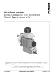
• 15P0701B100•
REMOTE
MONITORING
SERVICES
USER MANUAL
Issued on 18/04/12
R.00
English
• This manual is integrant and essential to the services and the products described herein. Carefully
read the instructions given as they provide important hints for use and maintenance safety.
• The products and services covered in this manual are to be used only for the purposes they have been
designed to. Any other uses should be considered improper and dangerous. The Manufacturer is not
responsible for possible damages caused by improper, erroneous and irrational uses.
• The products and services covered in this manual are sold according to Elettronica Santerno’s sales
and guarantee terms.
• Elettronica Santerno reserves the right to make any technical changes to this manual and to the
products described herein without prior notice. If printing errors or similar are detected, the corrections
will be included in the new releases of this manual.
• The information contained herein is the property of Elettronica Santerno and cannot be reproduced.
Elettronica Santerno enforces its rights on the drawings and catalogues according to the law.
Elettronica Santerno S.p.A.
Strada Statale Selice, 47 - 40026 Imola (BO) Italy
Tel. +39 0542 489711 - Fax +39 0542 489722
santerno.com [email protected]
Remote Monitoring
Services
User Manual
0. TABLE OF CONTENTS
0. TABLE OF CONTENTS ............................................................................................2
0.1. INDEX OF FIGURES ............................................................................................... 2
1. GENERAL INFORMATION .......................................................................................3
1.1. REMOTE MONITORING SERVICES ....................................................................... 3
1.2. MAIN FEATURES .................................................................................................... 3
1.3. SCOPE OF THIS MANUAL ...................................................................................... 4
2. DESCRIPTION OF THE REMOTE MONITORING SYSTEM....................................4
2.1. OVERVIEW OF THE WHOLE SYSTEM .................................................................. 4
2.2. FUNCTIONALITY OF EACH DEVICE IN THE REMOTE MONITORING SYSTEM.. 5
2.2.1.
LOCAL SUPERVISOR COMPUTER OF THE PLANT .................................................. 5
2.2.2.
ES851 DATA LOGGER BOARD INSTALLED ON THE INVERTER ............................. 6
2.2.3.
COMPONENTS IN THE WEB SYSTEM ....................................................................... 7
3. SERVICE ACTIVATION ............................................................................................8
4. ROUTINE MAINTENANCE .......................................................................................8
5. DESCRIPTION OF THE SERVICES .........................................................................9
5.1. LINK SERVICE ....................................................................................................... 9
5.2. LOG MANAGER SERVICE ...................................................................................... 9
5.3. SUNWAY PORTAL ................................................................................................ 10
5.3.1.
SUNWAY PORTAL REAL TIME, MAP ........................................................................ 12
5.3.2.
SUNWAY PORTAL REAL TIME, SUMMARY ............................................................. 13
5.3.3.
SUNWAY PORTAL REAL TIME, PLANT SCHEMATIC .............................................. 14
5.3.4.
SUNWAY PORTAL, CHARTS ..................................................................................... 15
5.4. SUNWAY PORTAL, HISTORY DATA .................................................................... 16
6. E-MAIL AND SMS MESSAGING.............................................................................17
6.1. ADDRESSEES....................................................................................................... 17
6.2. NOTIFICATION MESSAGES ................................................................................. 17
6.3. CONTENTS OF E-MAILS AND SMS MESSAGES ................................................ 17
0.1.
Index of Figures
Figure 1: The whole Remote Monitoring system ................................................................................................4
Figure 2: Remote Sunway, Inverter Control Panel .............................................................................................9
Figure 2: Sunway Portal home page.................................................................................................................10
Figure 3: Real Time, Map .................................................................................................................................12
Figure 4: Real Time, Map, Plant Sheet .............................................................................................................13
Figure 5: Real Time, Summary .........................................................................................................................13
Figure 6: Real Time, Plant Schematic ..............................................................................................................14
Figure 7: Real Time, Charts..............................................................................................................................15
Figure 8: History Data .......................................................................................................................................16
2/18
User Manual
Remote Monitoring
Services
1. GENERAL INFORMATION
1.1.
Remote Monitoring Services
This manual covers the remote monitoring services offered from Elettronica Santerno SpA. The remote
monitoring services allow our customers to get updated information and data from their photovoltaic plants,
receive diagnostic messages and check the correct operating conditions of their plants at any time.
Besides controlling the correct operation of the PV plants in remote mode and receiving diagnostic
messages, users can also change the operating parameters of the plant devices.
1.2.
Main Features
Elettronica Santerno SpA offers the following remote monitoring services:
•
Link Data Service: this is a remote connection via the Remote Sunway suite enabling communication
with ES851 Data Logger boards
•
Sunway Connect Data Service: establishes a remote connection enabling communication with the
stand-alone data logger
•
Sunway Portal web service: web portal, available at https://www.sunwayportal.it; allows doing the
following:
o
Real Time Data display
o
History Data display
o
E-mail or SMS diagnostic messaging
Minimum requirements: the plants shall be equipped with at least one ES851 Data Logger board or Sunway
Bridge. The inverters of the Sunway M XS series from Santerno are equipped with an integrated data logger
and are capable of sending data in an independent way. The Sunway M XS inverters, however, may also be
monitored by an ES851 Data Logger board or by a Sunway Bridge.
Only the remote monitoring services are covered in this manual.
NOTE
For details on the devices below, please refer to their respective manuals:
•
Local supervisor computer of the plant
•
Remote Sunway suite
•
ES851 Data Logger board
•
Sunway Bridge
•
Smart String Box
•
Sunway inverters
•
Sunway M XS inverters
3/18
Remote Monitoring
Services
1.3.
User Manual
Scope of this Manual
This manual covers the following:
• exhaustive comprehension of the remote monitoring services provided from Elettronica Santerno
• choice of the configuration fitting the customer’s needs
• usage of the remote monitoring services
2. DESCRIPTION OF THE REMOTE MONITORING SYSTEM
2.1.
Overview of the Whole System
Remote Sunway
CUSTOMER’S STAFF
(they establish a connection to ES851 Data Logger or the
plant local supervisor PC)
LOG_MANAGER
SUNWAYPORTAL
WEB Browser
Firewall + SMTP
Internet
DATABASE
STAFF MANAGING THE CUSTOMER’S
PLANTS
(they connect to www.sunwayportal.it)
http://www.sunwayportal.it
ftp://data.elettronicasanterno.it
http://link.elettronicasanterno.it
Connections active in ports 15101 to 15297
Alive over port 15100
Firewall
Router-DHCP-DNS-GATEWAY
PV Plant LAN
FTP
RS485
ES851
data logger
Local supervisor in Inverter 1
PC of the PV plant
ES851
data logger
in Inverter 2
RS485
ES851
data logger
in Inverter 3
RS485
ES851
data logger
in Inverter 4
RS485
RS485
Smart String Box
Smart String Box
Smart String Box
Smart String Box
Smart String Box
Smart String Box
Smart String Box
Smart String Box
Smart String Box
Smart String Box
Smart String Box
LINK
Smart String Box
Figure 1: The whole Remote Monitoring system
4/18
User Manual
2.2.
Remote Monitoring
Services
Functionality of Each Device in the Remote Monitoring System
2.2.1. Local Supervisor Computer of the Plant
The local supervisor computer of the PV plant is connected to the local are network (LAN) with an Ethernet
cable. The LAN shall do the following:
• Provide a valid IP address, either a static address or a DHCP (Dynamic Host Configuration Protocol)
address
• Provide a valid and reachable DNS (Domain Name System)
• Provide fast access to the Internet 24 hours a day, without using any proxy and without any
hardware/software check on the web traffic
• Keep TCP ports open (output, from 15100 to 15300) to the link.elettronicasanterno.it
• Keep TCP ports open (output) for FTP traffic
The local supervisor computer must be powered on 24 hours a day. A specific version of the Remote Sunway
shall run on the local supervisor computer.
Full functionality is ensured only if no application other than the Remote Sunway is installed on the local
supervisor computer.
The local supervisor computer may be connected to the plant devices in two mutually exclusive modes:
- via RS845, using the Modbus RTU protocol
- via Ethernet, using a proprietary protocol.
The computer is a Master device, i.e. it can query all the connected devices below:
• ES851 Data Logger (DL) boards
• Sunway TG (ST) Inverters
• Sunway M XR (SM) Inverters
• Sunway M Plus (SP) Inverters
• Sunway M XS inverters (SA and SL)
• Smart String Boxes (QF)
• DC-Parallel (QPS)
• AC-Parallel (QPCA)
• DATEXEL I/O (XD and XA) devices
• Meteo Station (MZ)
• Device detecting grid voltage and grid current measures (XF)
• PLCs (CL)
NOTE
For details about the devices above, please refer to their respective User Manuals.
Here is a list of the functions performed by the local supervisor computer of the PV plant:
• The local supervisor displays a synoptic table including the main measures of the plant; measures are
sampled and displayed approx. every 10 seconds.
• Every 5 minutes, the local supervisor PC sends an “Alive” message to the LINK service; this message
indicates that the PC can be reached from remote users. From their remote computer, the customer’s
technicians can establish a connection to the local supervisor computer of the plant through the LINK
service (the Remote Sunway suite is required, as well as a “username” and “password” for login) and
can establish a connection to any device that can be reached from the local supervisor computer.
• Every 15 minutes, the local supervisor PC samples approx. 150 variables from the plant device and
sends them to the FTP server.
5/18
Remote Monitoring
Services
User Manual
2.2.2. ES851 Data Logger Board Installed on the Inverter
The ES851 Data Logger board is connected to the Local Area Network via the Ethernet cable.
The LAN shall do the following:
• Provide a valid IP address, either a static address or a DHCP address
• Provide a valid and reachable DNS
• Provide fast access to the Internet 24 hours a day, without using any proxy and without any
hardware/software check on the web traffic
• Keep TCP ports open (output, from 15100 to 15300) to the link.elettronicasanterno.it
The ES851 Data Logger board is installed on an inverter.
NOTE
When the LOGGING function is required, or when diagnostic messaging is enabled also at nighttime, the inverter must be continuously supplied with auxiliary power supply.
Every 5 minutes, the ES851 Data Logger board sends an “Alive” message to the Sunway Portal via the LINK
service. This message indicates that the board is activated and may be reached from remote users.
The ES851 Data Logger board dialogues with the inverter where it is installed and may have 2 external
RS485 links:
• May be connected to the local supervisor computer through RS485 or Ethernet cable. The ES851 Data
Logger board acts as a “Slave” and responds to the read/write queries for parameters and measures
sent from the local supervisor computer, and submits the read/write queries for the inverter where it is
installed
• If the ES851 board is connected to the local supervisor computer via RS485, the Modbus RTU protocol
is used; otherwise, if an Ethernet cable is used, a proprietary TCP/IP protocol is used.
• The ES851 board has an additional RS485 port using the Modbus RTU, where it acts as a “master”
and can then read and write measures and parameters relating to all the devices connected to that
RS485 Modbus RTU cable.
• If properly configured, the ES851 board may be connected to an external Master via standard Modbus
TCP/IP; this protocol, however, is not currently supported by the Remote Sunway.
The two RS485 links are segregated from each other, i.e. they are two separate hardware ports: COM1 and COM2.
From the local supervisor computer, ES851 can then communicate with the inverter where it is installed and
with the slave devices connected to the additional RS485 link.
If properly configured, ES851 Data Logger board can do the following:
•
Sample the measures read from the inverter every 2 minutes and store to the flash memory the
measures read from the inverter where it is installed or from the devices it is connected to. Also, the
date and time of each sampling round is stored to the log files. When the maximum allowable
dimension of the log file is achieved, the ES851 restarts writing from the beginning of the file (circular
buffer).
•
Monitor the logged devices and detect the “Events” fired. These “Events” can be alarms, i.e.
persistent alarms triggered or THEFT signals sent from a String Box.
If no response to a query of the Data Logger board is received after 3 enquiry attempts, a “NON
RESPONSE” event fires. All the events fired are stored to an EVT file.
•
Send to Sunway Portal, via the LINK service, the signals for the detected events. Events can be
“ALARMS”, “THEFT” events and “NON RESPONSE” events.
•
Perform a smart sorting of the detected events to avoid uncontrolled messaging when the RS485
cable is fully disconnected, or to avoid continuous event firing from one of the monitored devices.
6/18
User Manual
Remote Monitoring
Services
2.2.3. Components in the Web System
2.2.3.1. Link Service
This is a server receiving the following:
• the “Alive” messages sent from the Data Logger board and the PCs in the PV plant
• the connection queries from the users who want to establish a connection to the Data Logger boards or
the local supervisor computers in the plant via the Remote Sunway suite
• the data items sent to ES851 boards to be received by the Sunway Portal
• the notifications for the alarms tripped from a device connected to the ES851 board
Any query is authenticated and authorised through a strict check on the identity of the caller (user or ES851
board or local supervisor computer) and on the type of query.
When an Alive message is received, the caller status is updated and the system stores the last instant when
the caller has been detected as online.
When the user queries the list of the ES851 boards installed, the system will easily detect when a given board
has been seen online for the last time.
When data items are received, they are submitted to the Sunway Portal, which will properly store them to
Santerno’s storage system.
When an alarm notification is received, this is submitted to the Sunway Portal, which applies filter and
categorization algorithms and sends an e-mail or SMS to a list of addressees shared with the customer.
When a connection request is received, a safe communication channel is created between an ES851 board
or the local supervisor computer and a remote user using the Remote Sunway. The user will then be able to
read the measures of the devices connected to the other end-point and change the relevant operating
parameters.
2.2.3.2. Log Manager
This is a service made available for whom has purchased the service enabling viewing history data. It
periodically connects to the remote data logger boards and downloads the files including stored data. Those
files are then stored to Santerno’s storage servers and are made available to the customers via the FTP
service.
2.2.3.3. FTP
This is a standard FTP server receiving the files containing the data stored every 15 minutes. It also receives
the ZIP files sent from the LOG_MANAGER and containing the data stored from the Data Logger boards of
the customers who purchased the HISTORY service of the Sunway Portal.
2.2.3.4. Sunway Connect
This is a service dedicated to the connections between a remote user and a Stand Alone data logger
enabling a connection between the data logger and the Remote Sunway.
2.2.3.5. Sunway Portal
This is a web portal available at https://www.sunwayportal.it that can be accessed by customers only. It stores
real-time data and makes them available to the users.
7/18
Remote Monitoring
Services
User Manual
The Sunway Portal includes the following:
• The “Map”, showing the location of the plant through a colour marker
• The “Plant Data”, including a chart containing the main production data of the PV plant and of each
individual subfield.
• The “Plant Schematic”, reproducing the connected devices. Different colours are given to indicate the
operating conditions of the devices. When pointing to each device, its main measures are given.
• A “Charts” section, representing output data and solar radiation in a Cartesian graph. The graph allows
zooming in/out and detecting specific measures in selected spots. It also allows data export to csv or
pdf files. If purchased, the history data service allows querying a system with no time constraints;
otherwise, only the data logged during the last week will be available.
3. SERVICE ACTIVATION
In order to get the remote monitoring service activation, the purchaser shall provide the technical data of the
PV plant required for the service, as well as the e-mail address or the phone number for SMS receiving
reports or alarm notifications.
The forms to be filled in for the service activation are available from Elettronica Santerno.
The remote monitoring services are activated only when complete and exhaustive information is given to
Elettronica Santerno. The quality of the service is dependant on the information given.
Should PV plant data be changed, please contact Elettronica Santerno to purchase a new configuration
service.
4. ROUTINE MAINTENANCE
Elettronica Santerno constantly enhances all the remote monitoring services provided. Improvements are
made with no obligation of communication.
8/18
Remote Monitoring
Services
User Manual
5. DESCRIPTION OF THE SERVICES
5.1.
Link Service
The LINK service allows the remote connection via the Internet to the local supervisor computer or ES851
Data Logger boards.
The Remote Sunway 2.30 (or later) installed on the user’s laptop allows establishing a connection to each
inverter or to the plant devices as if the laptop was connected directly to the PV plant.
The Remote Sunway allows measure readout, configuration parameter write, chart creation and real-time
data storage.
For any details on the Remote Sunway 2.30 suite, please refer to the relevant User Manual.
Figure 2: Remote Sunway, Inverter Control Panel
5.2.
Log Manager Service
The Log Manager service is configured for periodic download of the data stored to the local supervisor
computer or the Data Logger boards.
Donwloads are compressed to zip files and stored to the FTP home of the customer to the Santerno FTP.
9/18
Remote Monitoring
Services
5.3.
User Manual
Sunway Portal
This service is available at https://sunwayportal.it. Make sure that your browser is updated with the latest
release available for the operating system you are using. Elettronica Santerno reserves the right to provide no
support for certain browser versions, such as Internet Explorer 6; the supported browsers, however, are listed
on the home page of the portal.
The service receives data from the data loggers installed. Data items are then aggregated and processed to
provide measures detected from individual plants or from the whole plant set of the customer. The Sunway
Portal service also provides graphical representations allowing monitoring the plant operation and evaluating
energy production in real-time.
Figure 3: Sunway Portal home page
Six languages are available: English, Italian, French, German, Spanish, Portuguese. The site can be
accessed even from the registered domains below:
www.sunwayportal.de
www.sunwayportal.es
www.sunwayportal.com
10/18
User Manual
Remote Monitoring
Services
If your login is correct, you can access the page of the Real Time service.
This service includes four main items:
• The Map
• The Plant Set
• The Plant Schematic
• The Real Time Charts
The Map is the first option displayed. It shows the location of the plant. Virtual traffic lights indicate the correct
operation of the plant, and a status bar indicates the power production as a percentage of the rated power of
the inverters installed. The overall, average solar radiation of a PV plant is available if that plant is provided
with solar radiation sensors.
The List views a table containing information similar to that given by the Map.
The Plant Summary views some tables containing the production data of the virtual plant set of the customer,
including individual plants and subfields, as well as environmental sensors, when available.
The Plant Schematic displays a diagram of the plant indicating the monitored inverters and devices. The
operating conditions of each device are shown. Virtual traffic lights also indicate if the energy produced is as
expected.
The Charts graphically represent the power production in a Cartesian graph. The charts include power,
energy, solar radiation. Data items are sorted by device or by sensor. The time period may be up to seven
days.
11/18
Remote Monitoring
Services
User Manual
5.3.1. Sunway Portal Real Time, Map
The Map is a service integrated with Google Maps. From the commands on the left you can identify the
location of the plant, filter the plants by status, select the navigator and zoom in up to the maximum available
level.
Figure 4: Real Time, Map
Colours of the virtual traffic lights:
•
GREEN
The plant is properly operating and the energy production is correct
•
YELLOW
One of the inverters in the plant is underproducing energy
•
RED
An alarm tripped in one of the inverters in the plant
•
WHITE
No data is available
The marker hand indicates the instantaneous production of the plant as a percentage of the rated power of
the inverters installed.
The bar above the marker indicates the overall solar radiation as a percentage of a theoretical maximum
2
solar radiation of 1100 kW/m .
If you click on the marker, a popup appears showing the summary of the plant data.
12/18
Remote Monitoring
Services
User Manual
Figure 5: Real Time, Map, Plant Sheet
The summary data items relate to the plant status (indicating how many inverters are currently running, i.e.
are properly operating), instant power and energy, installed power and date of commissioning of the plant.
5.3.2. Sunway Portal Real Time, Summary
The Plant Set views the production data of the virtual plant set, the data of each plant and subfield, as well as
the data from the ambient sensors, when available. If auxiliary devices are installed, such as meteo centres,
their measures are also displayed.
Figure 6: Real Time, Summary
13/18
Remote Monitoring
Services
User Manual
5.3.3. Sunway Portal Real Time, Plant Schematic
The Plant Schematic displays a diagram of the plant indicating the monitored inverters and devices. Virtual
traffic lights indicate the operating conditions of each device. Traffic lights also indicate if the energy produced
is as expected.
Figure 7: Real Time, Plant Schematic
When pointing to each monitored device, a window appears showing all the measures sampled from the
device.
When the strings are monitored through the Smart String Boxes as shown in the figure, the virtual traffic light
is green if the output power produced from the monitored strings is approx. as expected. The expected power
is get from the ambient measures detected from solarimeters, thermometers, anemometers and from the
data of the PV panels of the strings connected to each Smart String Box.
COLOURS OF THE VIRTUAL TRAFFIC LIGHTS:
For each ES889 board installed on the Smart String Boxes, (QF):
The output power of the strings is correct
The strings are underperforming or their output power is too weak
No data is available
14/18
Remote Monitoring
Services
User Manual
For the SunwayTG or Sunway M XR / M Plus inverters:
Properly operating
Inverter in stop
Night-time or adverse weather conditions
Inverter in an emergency
No data is available
5.3.4. Sunway Portal, Charts
The Real Time Charts represent the daily production of power, energy and solar radiation. Data items are
sorted by device.
Figure 8: Real Time, Charts
15/18
Remote Monitoring
Services
5.4.
User Manual
Sunway Portal, History Data
The History Data service allows creating the charts showing power output starting from the date of
commissioning of the plant. Data may be downloaded to csv files.
Production data may be viewed and downloaded on a daily, weekly, monthly, yearly basis. The user may also
set a different time period by choosing the start date/end date from the relevant fields.
Figure 9: History Data
16/18
User Manual
Remote Monitoring
Services
6. E-MAIL AND SMS MESSAGING
The Sunway Portal parses any data items sent from the PV plants and analyses the operating conditions of
the data loggers. If malfunction occurs, e-mail or SMS notifications are sent. The text of the messages is
given in section 6.2 and may convey information relating to multiple devices.
Elettronica Santerno reserves the right to change the text of the messages at any time and without prior
notice for a better fruition of the service.
6.1.
Addressees
The addressees of e-mail and/or SMS notifications may be chosen granularly by specifying the contacts, the
days of the week and the allowable time spans, the submit rules and the type of messages to be sent.
This is done directly by Santerno Customer Service.
It may happen that not all the options above can be applied during the activation stage of the service.
6.2.
Notification Messages
Notification messages are sent when an event fires, or when an event disappears and normal operating
conditions are restored.
Notification messages can be of 4 types:
• Alarm
• Panel theft
• Remote communications failure
• Local communications failure
Because data items are periodically parsed every few minutes, notifications are not sent individually but are
grouped together: this means that different types of messages or from different PV plants may be included in
the same e-mail or SMS, especially if the addressee is configured for more than one plant.
6.3.
Contents of E-mails and SMS Messages
The content of the e-mails and SMS states the plant where the alarm(s) tripped or the event(s) fired, the
affected device and a brief description of the event. The cause responsible for the alarms/events can be
easily identified.
For example, if the system detects that some strings in a plant are open, it sends the following message to
one ore more addressees:
Dear Customer,
The following events have been detected:
Plant: santerno.imola
Device: Santerno Imola Cab23 Jb43
String status (QF105X) is 8: String Open
on 09/12/2011 09:05
Please state code 1573 for assistance.
Plant: santerno.imola
Device: Santerno Imola Cab23 Jb44
String status (QF105X) is 8: String Open
on 09/12/2011 09:05
Please state code 1574 for assistance.
Best Regards
Monitoring & Automation Team
17/18
Remote Monitoring
Services
User Manual
In the example above, two alarm messages have been included in one notification message. If assistance is
required, the Remote Monitoring Service shall be informed about the two alarm codes stated in the message
above.
If the “read failure” rate exceeds 70% (serious communication failure), the data logger of the PV plant will
send a message similar to the following:
Dear Customer,
The following events have been detected:
Plant: santerno.imola
Device: Santerno Imola Cab1 Jb2
Read failure rate (QF105X) is higher than 70%
Please state code 174 for assistance.
Best Regards
Monitoring & Automation Team
If an inverter is in an emergency, the alarm notification is similar to the following:
Dear Customer,
The following events have been detected:
Plant: santerno.imola
Device: Santerno Imola Cab3 St2
Current Alarm (ST171X): A065 Main Switch Off
Please state code 174 for assistance.
Best Regards
Monitoring & Automation Team
If no Internet connection is established to the data logger of the plant, the failure notification is similar to the
following:
Dear Customer,
The following events have been detected:
Plant: santerno.imola
Device: Santerno Imola Cab3 St2
Data logger: Santerno Imola ES851 is offline
Please state code 174 for assistance.
Best Regards
Monitoring & Automation Team
18/18