1
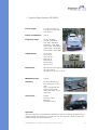
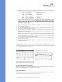
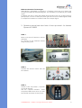
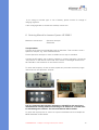
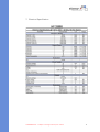
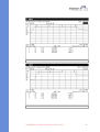
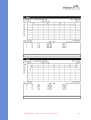
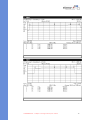
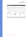
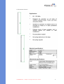
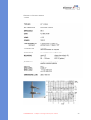
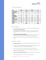
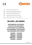
VIP High Power Convoy Jammer 3260S Manual CONFIDENTIAL – Subject to–change prior notice!prior notice! CONFIDENTIAL Subjectwithout to change without 1 VIP High Power Convoy Jammer 3260S Manual Content 1. Technical Specifications HP 3260S .............................................................. 3 2. Proposal on ECM Jammer Systems against Terrorist’s bomb attacks during Convoy Operations ........................................................................... 4 3. Operation manual and short form of start up manual for Jammer System HP 3260S.......................................................................... 6 4. ABC Charger ................................................................................................ 7 5. Trouble shooting and service ....................................................................... 9 6. Servicing Manual for Jammer System HP 3260 S ..................................... 10 7. Electrical Specification ............................................................................... 11 8. Specifications of Antennas ........................................................................ 16 9. Batteries ..................................................................................................... 25 10. Contact ....................................................................................................... 29 Safety Instructions The unit HP 3260S is a Jammer. Jammers are transmitters which transmit millions of frequencies at the same time to block any type of receiver. A Jammer is a high frequency transmitter. Therefore there are typical terms of use which have to be known during transmission. A safety distance to the antennas is necessary. Safety Instruction Electromagnetic waves can be dangerous for your health. For example we can give no statement regarding the effects on pacemakers at the moment. Therefore we suggest that people with pacemakers do not use any kind of transmission units or any kind of transmitters, as well as Jammers, were not used direct to people with a pacemaker. During transmission All doors and windows have to be closed. Outside the vehicle a safety distance from the antennas has to be taken. The use and operation of the Jammer is only allowed to trained people and end users. CONFIDENTIAL – Subject to change without prior notice! 2 1. Technical Specifications HP 3260S Power supply: 12 V DC from the car 24 V DC from the Jammer battery Power consumption: 470 W Frequency range: HF 20 - 80 MHz VHF 80 - 200 MHz UHF 200 - 500 MHz SHFI 500 - 1000 MHz SHFII 1000 - 2000 MHz SHFIII 2000 - 2500 MHz SHFIV 2500 - 3000 MHz Output power: HF 150 W VHF 125 W UHF 100 W SHFI 40 W SHFII 25 W SHFIII 15 W SHFIV 10 W Dimensions: Jammer 46 x 52 x 28 cm 46 x 52 x 28 cm Voltage Con. 46 x 52 x 15 cm Modulation Type: Sweep Antennas: HF Omni-Directional VHF Antennas for HF, VHF UHF Log-periodic Ant. SHFI for UHF, SHFI SHFII and SHFII+III+IV SHFIII+IV Accessories: Cables Remote control Batteries Special roof box Operation After the Jammer is assembled and installed to the car, including all cables for the supply voltage and antennas. It is ready for use. The Jammer should never be operated without connected antennas. CONFIDENTIAL – Subject to change without prior notice! 3 The first step for operation is to activate the keyswitch at the remote control to put the Jammer into stand-by mode. Now the single channels can be activated by the corresponding switches. The remote control will also show the channel status (ON/OFF). 2. Proposal on ECM Jammer Systems against Terrorist’s bomb attacks during Convoy Operations Electronic Counter Measures (ECM) or Jamming Systems which are designed to provide protection for VIPDignitaries against attacks by radio control. Improvised Explosive Devices (RCIED’s) is a delicate and complicated task. Nobody knows when, where, on which frequency, what distance between bomb and terrorist & what distance between VIPCar and bomb during the attack. ONLY THE TERRORIST KNOWS AND HAS A COMPLETE CONTROL ABOUT THE WHOLE SCENARIO. Therefore the VIP protection must be on a very high sophisticated level. Elaman the manufacturing company of such protection systems with experience all over the World - Europe, Near East, Middle East, Far East, Africa and America – since more than 20 years in business – has developed the HP ECM Series to the clients specifications and needs. Due to this long experience and the back-up with the user and clients we can give the following proposal: 1. IT must be a SYNTHESIZED SWEEP JAMMER no barrage or white noise which was already used in World War 2 and is an old technique. 2. NEVER USE FOR CONVOY OPERATION BARRAGE OR WHITE NOISE. 3. The lowest frequency should be around 20 MHz or 25 MHz. 4. The highest frequency should work now around 2000 MHz or higher 2,5 GHz and if required also up to 3 GHz. 5. Between both frequencies there should be no gaps. Nobody knows whichfrequency the terrorist is using. 6. For the own communication there are other tactical solutions which should only be discussed personally. 7. The unit should be MODULAR each channel is working on its own. NO breakdown of the whole system if one channel is out of us the others are still in full operation. Easy for repair, easy for maintenance, easy for upgrading in new technology or higher frequencies. So no black box with no function if something is wrong always modules. CONFIDENTIAL – Subject to change without prior notice! 4 8. Different output power for the different channels. During all our tests and experience with our clients we would suggest: VHF 20 – 80 MHz about 125 to 150 W VHF 80 – 200 MHz about 125 W UHF 200 – 500 MHz about 100 W SHF 500 – 1000 MHz about 40 W SHF2 1000 – 2000 MHz about 25 W SHF3 2000 – 3000 MHz about 15 W The Channel HF and VHF have no gain with the used antennas all the other channels have a gain up to + 11 dBi. With these output powers the safety range is more than 250 meters in all directions which is more than sufficient to protect the VIPs. 9. Never install the Jammer HP 3260S into the VIP car – always escort cars for more flexibility and safety. 10. 10. Use 2 HP 3260 S – one in front and one in the back of the VIP car or convoy – for the double protection range. 11. The HP 3260 S is installed in all kinds of Off-Road Cars. Range Rover, Land Rover, MB V, G, M, Toyota Landcruiser, GMC Suburban, Nissan Patrol, Embassador, Ford Explorer etc. 12. The HP 3260 S is easy to operate. If installed once the operator can see and control each channel on its own, he has full information about power supply and RF transmission – everything is shown on the remote control and on the unit itself by LEDs and other optical means. 13. We suggest a maintenance contract with our company to check the HP ECM Series every two years. 14. Elaman will give complete support for training, advice of spare parts and measure instruments. We, Elaman, are proud to mention that all Jammers once supplied to our customers and installed into the various cars are in full operation although some of them are in use for more than 12 years. Double Digital Sweep Technology: We use three special IC’s, which generate the sweep signals. These signals are being tuned digitally to each single frequency range. Type of Modulation We add to the carrier of the sweep signals a FM modulation. We jam with our DDS all AM/ FM/ SSB signals either analog or digital. CONFIDENTIAL – Subject to change without prior notice! 5 Difference between Technologies White Noise is generated via a Diode or a Transistor which due to its nature can not be fine tuned (see attached diagram). This possibility is provided by the sweep signal. In addition we like to stress that White Noise signals loose a lot of their initial capacity/output, as most of the input power get lost into heat. Double Digital Sweep in comparison maintains a constant Level of the output Signal. 3. Operation manual and short form of start up manual for Jammer System HP 3260S STEP 1 Never use the HP Jammers without antennas! So connect on the antennas before doing anything else! STEP 2 Connect the remote control with the HP Jammer. STEP 3 Switch on the “key switch”, to power on the HP Jammer. Use the “channel switches”. There are special LEDs which show you that the Jammer channels are one power. CONFIDENTIAL – Subject to change without prior notice! 6 Special RF LEDs show you, that the Jammer is working and that there is power on the antennas. CHARGING To charge the battery pack of the HP 3260 S Jammer, connect the power pack with 230V. There is a LED which shows you the charging status. RED The unit is charging. YELLOW The unit is still charging. 80-90% of the capacity is charged. GREEN The unit is complete charged. 4. ABC Charger User Manual • Read this instruction before the charger is taken into use. • Keep this manual within easy reach for the user of this battery charger. • Hydrogen gas will be produced when charging lead-acid-batteries and hydrogen gas is explosive. • Open flames and sparks should be kept away from batteries they may produce Explosions. • The charger should be switched off before the charger/battery plug is disconnected. • It is related with real danger to touch any parts inside the charger. Do not do any repair work with the main switch ON and to be real sure disconnect the mains connector. General The ABC Charger is suitable both for Freely Ventilated-(Wet) and Valve Regulated(Dry) lead/acid batteries. The charger is small and very light (1,5 kg) an can therefore easily be fitted close to the battery. (The charger can be delivered with program compensating for the equipment base load.) The charger operates in high frequency and should be connected to a standard 230 V mains connection with ground. The built in micro controller controls the charging process according to the chosen charging algorithm. During charging the charging progress is displayed with a status indicator LED on the front panel. The microcontroller is also controlling the charging progress with regards to Temperature in the charger an time. If a fault occurs in some cells or the temperature rises the charging current will be limited. If you have a special requirement of charging algorithm or application, please contact LEAB. CONFIDENTIAL – Subject to change without prior notice! 7 Installation The ABC Charger is mainly suited for indoor use. It can be used positioned horizontally on a table or a shelf, hang on a o-wall using the free supplied bracket or as a built-in charger in the vehicle or machinery. When it is built in it has to be shock absorbed. The charger can be with fixed connection to the battery or with conventional connectors. Position the charger in such a way that the air supply will not be obstructed. When the charger is fitted on a wall or mounted in a vehicle it should be horizontal to limit dust and moisture to enter it. Function Check that battery type and size correspond to the setting of the charger. Also check that the polarity between the charger and the battery is right. Positive + to positive + and negative – to negative –. Connect the battery to the charger and switch on the charger. The charging starts after a few seconds and the status indicator, Orange LED, is lit up. Orange LED remains on until the battery is fully charged. If the charger is connected to a fully charged battery the charger will be charging for 1 hour. This is the minimum charging time. Green LED, is lit up when the battery is ready to be used. Maintenance charging will continue as long as the battery is connected. ABC600/800: The charger will be reset as soon as the charger is switched off and then on. 1600W version is reset by the red knob on the front or by disconnecting the mains cable. The charging time depends on the size of battery and the depth of discharge. A freely ventilated battery (Wet) can be discharged to max. 800 and a valve regulated (Dry) with max. 70%. OBS: Switch off the charger before the battery is disconnected. If the battery is disconnected without switching off the charger, sparks may be produces. CONFIDENTIAL – Subject to change without prior notice! 8 5. Trouble shooting and service RED flashing LED may mean that the battery is not properly connected. Check cables, connection terminals, plugs and other connections to the battery. Rectify if possible. Measure the voltage at the battery and at the charger. If the connecting points and the voltage are correct, contact for consultation. Technical data Size: 600-800W/1600W L 230 x B 112 x H 75 I mm/ L 258 x B 136 x H 89 i mm Weight: 600-800W/1600W 1,5 kg / 2,3 kg Ambient Temperature: -25°C - +40° C Mains Voltage: 90 Volt – 255 Volt AC, 45Hz-400Hz (>200V will mean limited effect) If the charger is connected should be connected to a “c” characteristic fuse. Power Factor: ~1 Rated Voltage: 12 Volt, 24 Volt, 36 Volt, 48 Volt DC Rated Current: 15 Amp, 20 Amp, 30 Amp, 50 Amp, 60 Amp Secondary Cables: 2m 6/10 mm? Protection: 1, IP 21 (when fitted horizontally) Available in IP 44 General: Temperature controlled cooling fan. Protected against wrong polarity and short circuit. This charger can be used as a voltage supply. (Special program) CE-certified in accordance with valid EN-standards. Charging algorithms The ABC charger is designed for freely ventilated and valve regulated batteries. All chargers are equipped with app. 15 different charging curves. Every charging algorithm covers a specific battery capacity, which means that faulty adjustment will have an Impact on the battery lifetime. When is informed of battery capacity and type the charger will be delivered with the correct setting. CONFIDENTIAL – Subject to change without prior notice! 9 If you change to another type or size of battery, please contact for change of charging algorithm. If the wrong algorithm is chosen the warranty will be void. 6. Servicing Manual for Jammer System HP 3260 S Measures instruments: Spectrum Analyzer Wattmeter Test procedure: Connect the channel from 20-80 MHz with an attenuator. Then connect it with a Spectrum Analyzer, e.g. from Hewlett Packard. Put the Spectrum Analyzer on start at 15 MHz and on stop at 100 MHz. Connect the HP 3260 S with a cable to a battery or a kind of generator. Switch the “key switch” on the remote control ON. Then switch on the single channel from 20 to 80 MHz. Use the button on the remote control. To check the frequency of each channel, repeat this procedure with every single channel and on the Spectrum Analyzer. It is very important that all other channels are still OFF for this test. Every channel that is working without connecting to an antenna or a coaxial resistor will damage the Jammer. The relevant channel will be broken. To check the output power in watts use a special wattmeter like for example the BIRD Wattmeter model 4410A. CONFIDENTIAL – Subject to change without prior notice! 10 7. Electrical Specification CONFIDENTIAL – Subject to change without prior notice! 11 CONFIDENTIAL – Subject to change without prior notice! 12 CONFIDENTIAL – Subject to change without prior notice! 13 CONFIDENTIAL – Subject to change without prior notice! 14 CONFIDENTIAL – Subject to change without prior notice! 15 8. Specifications of Antennas HF Broadband Antenna CONFIDENTIAL – Subject to change without prior notice! 16 HF Broadband Antenna CONFIDENTIAL – Subject to change without prior notice! 17 HF Radiation Diagram HF Radiation Diagram CONFIDENTIAL – Subject to change without prior notice! 18 Element Loc-Periodic Antenna 200-500 MHz CONFIDENTIAL – Subject to change without prior notice! 19 Radiation Diagram at 350 MHz CONFIDENTIAL – Subject to change without prior notice! 20 Element Loc-Periodic Antenna 500-1000 MHz CONFIDENTIAL – Subject to change without prior notice! 21 Radiation Diagram at 850 MHz CONFIDENTIAL – Subject to change without prior notice! 22 Element Loc-Periodic Antenna 1-3 GHz CONFIDENTIAL – Subject to change without prior notice! 23 Radiation Diagram at 2 GHz CONFIDENTIAL – Subject to change without prior notice! 24 9. Batteries Jammer Battery AGM Absorbed Glass Mat (AGM) batteries Developed for aircraft, AGM batteries surround the lead plates with layers of glass mat, which is little more than damp with electrolyte.The result is that the batteries are particularly tough since the plates are well supported and there’s no electrolyte sloshing around. They are relatively new to the UK and European market, but are now the most popular battery type used in the American marine and recreational vehicle market. The battery is completely sealed and waterproof, and should continue to work even under the most extreme conditions. The battery has a very low self-rate of discharge providing exceptional life during periods of non-activity. Lifeline DMS technologies - Engineering with Energy General Technical Data • Technology Lead Calcium AGM (Absorbed • Glass Mat) • Voltage Range 12V and 6V options • Capacity Range 33AH to 255AH • High Rate Discharge Capability Good • Installation Any orientation • Cycle Life Approx 950 at 50% depth of discharge • Temperature Range 40°C to +60°C • High resistance to shock and vibration • Charge Regime Constant voltage unlimited current (fast charge) • Termination Din post/lug terminal • Shelf Life 2 years from full recharge • Non-hazardous, non-spillable cargo CONFIDENTIAL – Subject to change without prior notice! 25 Battery Technology Comparison Possible Applications • • • • • • • Marine Ancillary Equipment and Starting Motorhome Ancillary Equipment Caravan Ancillary Equipment Utilities Transportation Remote Power/Solar Recreational Vehicle Trolling Note: Laboratory testing has confirmed the amount of carbon present in batteries marketed is minimal, and in fact should be classed as Lead Calcium. CONFIDENTIAL – Subject to change without prior notice! 26 Typical Power Requirements Battery Care-Safety Large capacity batteries can be heavy, take care when handling all batteries. Do not short circuit the battery Red Flash and Lifeline batteries are designed to give very high starting currents therefore care must be taken not to short circuit the batteries in any way. Do not attempt to open the battery Red Flash and Lifeline batteries are sealed and cannot be opened in any way, this action would allow oxygen into the battery and render it useless. Always observe the correct polarity of the battery positive and negative terminals. Battery Care – Installation Use the recommended torque settings for battery terminals when installing. (RF4NM) (LL 7NM) Check that you have sufficient battery capacity prior to the installation or additional electronic/electrical marine applicances/equipment. Do not mix AGM, Gel or Wet batteries within the same battery bank. Ensure that your battery charger is working correctly prior to installation of batteries and at regular intervals. Never lift or lower the battery using the connection lead as this is dangerous and may damage the battery terminals. Ensure that the battery tray is clean and clear of any debris. CONFIDENTIAL – Subject to change without prior notice! 27 Battery Care - Routine Checks Check battery casing for damage Check battery connections are tight and not corroded. Fully charge battery bank to 100% capacity at regular intervals (every 60 days) Isolate the battery bank and fully charge prior to lay-up over winter. Fully charge battery after winter lay-up prior to first voyage. CONFIDENTIAL – Subject to change without prior notice! 28 CONFIDENTIAL – Subject to change without prior notice! 29