1
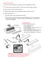
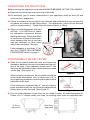
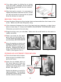
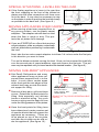
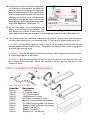
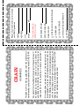
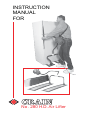
INSTRUCTION
MANUAL
FOR
No. 280 H.D. Air Lifter
SAFETY FIRST:
The Air Lifter is designed for moving furniture and appliances ONLY!
For use on flat, level floors ONLY! Do not use on inclines, stairs or ramps.
Do not ride or stand on the lifter plates.
Keep all body parts out from underneath heavy loads at all times.
Avoid electric shock:
DO NOT USE in wet or damp environments.
The Air Lifter comes with a three prong grounded plug. Do not remove the
ground from the plug. Use the Air Lifter with appropriate 3 prong power
cords and receptacles.
CONTENTS:
The Air Lifter comes with:
2 ea. Air Plates - "E"
1 ea. 2 HP Motor - "J"
2 ea. Air Plate to T-Connector hose - "C"
1 ea. T-Connector - "A"
1 ea. T-Connector to motor hose - "B"
4 ea. Plastic carpet adaptor glides - "I"
2 ea. Nylon carrying bags - not shown
CAUTION: When attaching or disconnecting
hoses, grab the solid plastic fitting, not the hose
itself. Pulling on the hose will cause damage.
NEVER pull the Air Lifter by the hoses!
1
OPERATING INSTRUCTIONS
Before moving any appliance or furniture ALWAYS BEWARE OF THE FOLLOWING:
Remove any items that may be on top of the load.
All electrical, gas or water connections to the appliance must be shut off and
removed from appliances.
Check the object to be moved for any delicate attachments that may contact the
air plates as a result of the lifting action. For appliances, check for the delicate
grills or ornamentation. These must be removed prior to lifting.
When you start the blower, the load
will rise. It is CRITICAL to check
for adequate clearance before
starting the motor. Check that there
is a minimum of three inches clearance between the top of the load
and any cabinetry or other items
which may be above the load.
MINIMUM
3 INCHES
Open the Air
Release Valve
If the clearance is less than 3", follow the POWER ADJUSTMENT
PROCEDURE listed on page 3.
Figure 1
POSITIONING THE AIR LIFTER
Slide the air plates under the load, and check the
clearance between the top of the plate and the bottom of the load. If the clearance is less than 3", the
load may be lifted without any extra blocking to make
up the gap. (See figure 2.)
Figure 2
When properly positioned, the air plates should be
as far apart as possible, but no closer than 1/4" to
any supporting members, and should project out the
backside of the load.
If the clearance is greater than 3", you will need to
place wooden blocks on top of the air plates before
sliding them under the load. (See figure 3.)
Wooden Block
Figure 3
If an air plate happens to get stuck as you slide it under, try rearranging the Air
Plates in a "V" shape under your load, or entering them from the opposite side.
"V" Entry
Approach
Side Entry
Approach
2
If no other option for sliding the air plates
under the load is available, tilt the load and
place blocks underneath the front corners.
(See figure 4.)
After the load is moved, it is necessary to
replace the blocks under the corners, or else
you will not be able to remove the air plates
when the blower is turned off.
Wooden
Block
Figure 4
MOVING THE LOAD
Insert the hose fittings into the air plate inlets and assemble the other hoses to the
motor. Make sure all hose fittings are snug.
If the clearance between the top of the load and any cabinetry or other items
above is less than 3", follow the POWER ADJUSTMENT PROCEDURE below.
Otherwise, proceed to the next step.
Strap the motor over your shoulder. Make sure the on/off switch on the motor is
readily accesible.
Place one hand on the appliance and turn the blower on.
The air plates will inflate quickly
and forcefully. BE PREPARED!
Move the appliance slowly and
steadily to the desired position.
DO NOT ROCK or push out of
balance. Maintain the load in a
level, controlled fashion AT ALL
TIMES. (See figures 5 & 6.)
Figure 5
Figure 6
POWER ADJUSTMENT PROCEDURE
This is best done with a helper.
Keep an eye on available clearance at all times.
Open the air release valve on
the hose that runs from the
motor to the T-Connector. This
reduces the lifting action of the
blower. (See figure 7.)
MINIMUM
3 INCHES
Open the Air
Release Valve
Switch the blower on and off in
rapid succession. The air plates
will partially inflate, and the load
can be moved out slowly.
Figure 7
3
SPECIAL SITUATIONS - LEVELLING THE LOAD
If the floating appliance is lower in the rear than
the front, stepping on the front of the inflated air
plates near the hose connections will force more
air to the back. It may also be necessary to step
on the plates in order to position the load as closely
as possible to the back wall. (See figure 8.)
Figure 8
MOVING APPLIANCES OVER CARPET
When moving a load over carpeted floor or
any porous surface, use the plastic carpet
adapters. The adapters should also be used
when the floor is rough or dirty. This protects the air plates from damage.
If you are STARTING on a floor that requires
carpet adapters, slide an adapter underneath
each air plate before positioning it underneath
the load.
Figure 9
Next, take the two extra carpet adapters tuck them 3-4 inches under the first pair,
in the direction you want to move.
Turn on the blower and start moving the load. Once you have moved the load fully
over the second pair of carpet adapters, stop and remove the first pair. This process may be repeated until you have reached the desired location. (See figure 9.)
MOVING SUB-ZERO® APPLIANCES
Sub-Zero® Refrigerators and many
other applicances may not have adequate frame supports built in to the
base. In such cases, certain areas
at the front and the rear edges of the
cabinet itself may provide the sturdiest support for lifting.
Remove all drip pans, grills and base
covers. Determine the best points for
lifting. Note especially any delicate
hoses or electrical wiring. Any such
hoses or wiring must be kept out from
under the lifting pressure of the plates.
FRONT EDGE
REAR EDGE
Blocks should be
under cabinet, NOT
UNDER DOOR.
Blocks should not
be under breakable
parts.
DO NOT LIFT by DOOR OR BREAKABLE
PARTS!
Depending on the available
space, blocks could be as
short as 3" in length.
Once the best points for lifting have
been determined, create a custom set
of wooden blocks that will support the
appliance as necessary. These are
to be placed on top of the air plate,
and then the air plate can be slid under the appliance. (See figure 10.)
Use a set of 8 to 10 wooden
blocks. They are made from
2x4's cut to 9" long and 3"
long.
Figure 10
4
In the case of a Sub-Zero® refrigerator,
for the front of the cabinet, the best surface for lifting is the flat area of the cabinet just behind the door. Be careful however to prevent the wooden blocks from
contacting the door, or any other breakable parts, such as the base cover or drip
pan supports, as this can cause major damage to the appliance. (See figure 11.)
FRONT EDGE
REAR EDGE
Blocks should be
under cabinet, NOT
UNDER DOOR.
Blocks should not
be under breakable
parts.
DO NOT LIFT by DOOR OR BREAKABLE
At the rear edge, the best surface for PARTS!
lifting is at the back of the cabinet. Do
Figure 11
not situate any blocks underneath the
back side cover or drip pan supports; or any exposed hoses or wiring. (See figure 11.)
At the rear edge, the available space may be limited. In this case, you may need
to use a narrower block (no narrower than 3") on top of a wider base block (9").
DANGER: All blocking supports used on top of the air plates must be level (at the
same height relative to each other). Otherwise, as the load lifts, it will not be level,
and the load may tip over.
DANGER: Sub-Zero® appliances are very heavy. Move appliances slowly and in
a controlled manner at all times.
DANGER: Sub-Zero® appliances may be very top-heavy, and may fall over under certain circumstances. Move the appliance slowly, and do not move over
ramps or stairs.
REPLACEMENT PARTS AVAILABLE
J
B
No. 280 AIR LIFTER
Order No.
1280-A
1280-B
1280-C
1280-D
1280-E
1280-F
1280-G
1280-H
1280-I
1280-J
1280-K
Description
T-Adapter
3' Flexible Hose
15” Flexible Hose
Replacement Flange
Air Plate Complete (1 only)
Blower Carrying Bag (not shown)
Air Plate Carrying Bag (not shown)
Blower Carrying Strap (not shown)
Plastic Pad Set (4)
Blower Complete
Brushes (2 - not shown)
5
All merchandise returned subject to this warranty must be
accompanied with same. All merchandise returned must be
F.O.B. Milpitas, California, and must be in complete assembled
units. No consideration will be given to unassembled parts. All
disputes will be up to the consideration of the CRAIN CUTTER
CO., INC. and their decision will be final.
Any parts of tools found defective subject to the guarantee will
be replaced at no charge. Credit in full or part cannot be
extended by the distributor. New tools will not be given as
replacements for those pending a warranty adjustment.
This 280 H.D. Air Lifter is guaranteed to be free of defects in
workmanship or quality of materials for a period of ONE YEAR.
GUARANTEE
CRAIN
❑
❑
❑
❑
❑
ZIP
OTHER
INSTALLATION CONTRACTOR
FLOORING DEALER
WORKROOM
INDIVIDUAL FLOORING INSTALLER
PLEASE CHECK:
DATE PURCHASED:
PURCHASED FROM:
TOOL PURCHASED:
#280 H.D. Air Lifter
STATE
CITY
ADDRESS
NAME
Please fill out and mail this card to validate
your CRAIN guarantee.
PLACE
STAMP
HERE
Crain Cutter Co., Inc.
1155 Wrigley Way
Milpitas, CA 95035-5426
Printed by: HW
FORM F1280-012003