1
UM1655
User manual
Audio Engine post-processing on STM32F4xx Omni2 multichannel library
Introduction
The Audio Engine post-processing on STM32F4xx - Omni2 multichannel library user
manual describes the software interface and requirements of the Omni2 multichannel
module. It has been designed for the audio application developers who integrate this
module into a main program. It provides a rough understanding of the underlying algorithm.
The Omni2 multichannel library implements the multichannel audio virtualization from mono
to 7.1 input signals, including the stereo widening effect for stereo inputs.
This library is part of the STM32-AUDIO100A firmware package.
July 2015
DocID025072 Rev 4
1/26
www.st.com
1
Contents
UM1655
Contents
1
2
Module overview . . . . . . . . . . . . . . . . . . . . . . . . . . . . . . . . . . . . . . . . . . . . 6
1.1
Algorithm function . . . . . . . . . . . . . . . . . . . . . . . . . . . . . . . . . . . . . . . . . . . . 6
1.2
Module configuration . . . . . . . . . . . . . . . . . . . . . . . . . . . . . . . . . . . . . . . . . 8
1.3
Resources summary . . . . . . . . . . . . . . . . . . . . . . . . . . . . . . . . . . . . . . . . . 8
Module Interfaces . . . . . . . . . . . . . . . . . . . . . . . . . . . . . . . . . . . . . . . . . . 10
2.1
2.2
3
4
2.1.1
omni2_reset function . . . . . . . . . . . . . . . . . . . . . . . . . . . . . . . . . . . . . . . 10
2.1.2
omni2_setParam function . . . . . . . . . . . . . . . . . . . . . . . . . . . . . . . . . . . 10
2.1.3
omni2_getParam function . . . . . . . . . . . . . . . . . . . . . . . . . . . . . . . . . . . 11
2.1.4
omni2_setConfig function . . . . . . . . . . . . . . . . . . . . . . . . . . . . . . . . . . . 11
2.1.5
omni2_getConfig function . . . . . . . . . . . . . . . . . . . . . . . . . . . . . . . . . . . 12
2.1.6
omni2_process function . . . . . . . . . . . . . . . . . . . . . . . . . . . . . . . . . . . . . 12
External definitions and types . . . . . . . . . . . . . . . . . . . . . . . . . . . . . . . . . 12
2.2.1
Input and output buffers . . . . . . . . . . . . . . . . . . . . . . . . . . . . . . . . . . . . . 12
2.2.2
Returned error values . . . . . . . . . . . . . . . . . . . . . . . . . . . . . . . . . . . . . . 13
2.3
Static parameters structure . . . . . . . . . . . . . . . . . . . . . . . . . . . . . . . . . . . 13
2.4
Dynamic parameters structure . . . . . . . . . . . . . . . . . . . . . . . . . . . . . . . . . 14
Algorithm description . . . . . . . . . . . . . . . . . . . . . . . . . . . . . . . . . . . . . . . 16
3.1
Processing steps . . . . . . . . . . . . . . . . . . . . . . . . . . . . . . . . . . . . . . . . . . . 16
3.2
Data formats . . . . . . . . . . . . . . . . . . . . . . . . . . . . . . . . . . . . . . . . . . . . . . . 16
3.3
Performance assessment . . . . . . . . . . . . . . . . . . . . . . . . . . . . . . . . . . . . . 17
Application description . . . . . . . . . . . . . . . . . . . . . . . . . . . . . . . . . . . . . 18
4.1
4.2
2/26
APIs . . . . . . . . . . . . . . . . . . . . . . . . . . . . . . . . . . . . . . . . . . . . . . . . . . . . . 10
System requirements and hardware setup . . . . . . . . . . . . . . . . . . . . . . . . 18
4.1.1
Recommended setup for stereo widening effect . . . . . . . . . . . . . . . . . . 18
4.1.2
Recommended setup for multichannel virtualizer effect . . . . . . . . . . . . 19
Recommendations for an optimal setup . . . . . . . . . . . . . . . . . . . . . . . . . . 20
4.2.1
Memory allocation . . . . . . . . . . . . . . . . . . . . . . . . . . . . . . . . . . . . . . . . . 21
4.2.2
Module API calls . . . . . . . . . . . . . . . . . . . . . . . . . . . . . . . . . . . . . . . . . . 21
4.2.3
Module integration summary . . . . . . . . . . . . . . . . . . . . . . . . . . . . . . . . . 23
DocID025072 Rev 4
UM1655
Contents
5
How to run and tune the application . . . . . . . . . . . . . . . . . . . . . . . . . . . 24
6
Revision history . . . . . . . . . . . . . . . . . . . . . . . . . . . . . . . . . . . . . . . . . . . 25
DocID025072 Rev 4
3/26
3
List of tables
UM1655
List of tables
Table 1.
Table 2.
Table 3.
Table 4.
Table 5.
Table 6.
Table 7.
Table 8.
Table 9.
Table 10.
Table 11.
Table 12.
Table 13.
Table 14.
Table 15.
Table 16.
4/26
Sampling rates . . . . . . . . . . . . . . . . . . . . . . . . . . . . . . . . . . . . . . . . . . . . . . . . . . . . . . . . . . . 6
Resources summary . . . . . . . . . . . . . . . . . . . . . . . . . . . . . . . . . . . . . . . . . . . . . . . . . . . . . . . 8
Frequency requirements (MHz) . . . . . . . . . . . . . . . . . . . . . . . . . . . . . . . . . . . . . . . . . . . . . . 9
omni2_reset . . . . . . . . . . . . . . . . . . . . . . . . . . . . . . . . . . . . . . . . . . . . . . . . . . . . . . . . . . . . 10
omni2_setParam. . . . . . . . . . . . . . . . . . . . . . . . . . . . . . . . . . . . . . . . . . . . . . . . . . . . . . . . . 11
omni2_getParam . . . . . . . . . . . . . . . . . . . . . . . . . . . . . . . . . . . . . . . . . . . . . . . . . . . . . . . . 11
omni2_setConfig . . . . . . . . . . . . . . . . . . . . . . . . . . . . . . . . . . . . . . . . . . . . . . . . . . . . . . . . . 11
omni2_getConfig. . . . . . . . . . . . . . . . . . . . . . . . . . . . . . . . . . . . . . . . . . . . . . . . . . . . . . . . . 12
omni2_process . . . . . . . . . . . . . . . . . . . . . . . . . . . . . . . . . . . . . . . . . . . . . . . . . . . . . . . . . . 12
Input and output buffers . . . . . . . . . . . . . . . . . . . . . . . . . . . . . . . . . . . . . . . . . . . . . . . . . . . 13
Returned error values . . . . . . . . . . . . . . . . . . . . . . . . . . . . . . . . . . . . . . . . . . . . . . . . . . . . . 13
Static parameters structure. . . . . . . . . . . . . . . . . . . . . . . . . . . . . . . . . . . . . . . . . . . . . . . . . 14
Dynamic parameters structure . . . . . . . . . . . . . . . . . . . . . . . . . . . . . . . . . . . . . . . . . . . . . . 15
Setup examples . . . . . . . . . . . . . . . . . . . . . . . . . . . . . . . . . . . . . . . . . . . . . . . . . . . . . . . . . 18
Virtualized sound compliant with ITU-T 7.1 speaker layout standards . . . . . . . . . . . . . . . . 20
Document revision history . . . . . . . . . . . . . . . . . . . . . . . . . . . . . . . . . . . . . . . . . . . . . . . . . 25
DocID025072 Rev 4
UM1655
List of figures
List of figures
Figure 1.
Figure 2.
Figure 3.
Figure 4.
Figure 5.
Figure 6.
Figure 7.
Mono to stereo perception for mono inputs . . . . . . . . . . . . . . . . . . . . . . . . . . . . . . . . . . . . . 7
Stereo widening perception for stereo inputs . . . . . . . . . . . . . . . . . . . . . . . . . . . . . . . . . . . . 7
Virtualizer perception (up to 7.1 channels) . . . . . . . . . . . . . . . . . . . . . . . . . . . . . . . . . . . . . . 8
Block diagram of the Omni2 module. . . . . . . . . . . . . . . . . . . . . . . . . . . . . . . . . . . . . . . . . . 16
Setup for stereo widening effect . . . . . . . . . . . . . . . . . . . . . . . . . . . . . . . . . . . . . . . . . . . . . 18
Setup for multichannel virtualizer effect . . . . . . . . . . . . . . . . . . . . . . . . . . . . . . . . . . . . . . . 19
API call procedure . . . . . . . . . . . . . . . . . . . . . . . . . . . . . . . . . . . . . . . . . . . . . . . . . . . . . . . 23
DocID025072 Rev 4
5/26
5
Module overview
UM1655
1
Module overview
1.1
Algorithm function
The module provides functions to handle mono to stereo expansion, stereo widening and
multichannel audio virtualization depending on the used library.
Table 1 describes the supported sampling rates and the input/output formats depending on
which library is used:
Table 1. Sampling rates
Library
Audio effect
Channel conversions
Supported sampling
frequencies
1.0 to 2.0
Mono2Stereo
1.0 to 3.0 (2.0 + center)
2.x to 2.0
Stereo Widening
lib_omni2_multichannel_m4
2.x to 3.0 (2.0 + center)
3.x to 2.0
32, 44.1 and 48 kHz
3.x to 3.0 (2.0 + center)
Stereo Widening for
matrix encoded input
2.xt to 2.0
2.xt to 3.0 (2.0 + center)
5.x to 2.0
Multichannel
Virtualization
5.x to 3.0 (2.0 + center)
7.x to 2.0
7.x to 3.0 (2.0 + center)
The module is fully functional and validated with the configurations in green in Table 1
above.
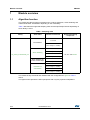
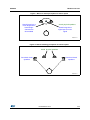
The figures below present the effect perception with only two physical loudspeakers.
6/26
DocID025072 Rev 4
UM1655
Module overview
Figure 1. Mono to stereo perception for mono inputs
$FWXDOSK\VLFDOVSHDNHUV
6RXQGLPDJHKDVD
PXFKODUJHUVL]HLI
OHIWDQGULJKW
FKDQQHOVDUH
GHFRUUHODWHG
6RXQGLPDJHKDVD
VLJQDOVSRWIRUPRQR
VLJQDO
069
Figure 2. Stereo widening perception for stereo inputs
$FWXDOSK\VLFDOVSHDNHUV
3HUFHLYHGYLUWXDO
VSHDNHUV
3HUFHLYHGYLUWXDO
VSHDNHUV
069
DocID025072 Rev 4
7/26
25
Module overview
UM1655
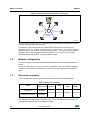
Figure 3. Virtualizer perception (up to 7.1 channels)
WŚLJƐŝĐĂů^ƉĞĂŬĞƌƐ
WĞƌĐĞŝǀĞĚsŝƌƚƵĂů
^ƉĞĂŬĞƌƐ
D^ϯϮϯϱϭsϭ
The virtualizer perception (up to 7.1 channels) gives the listener the impression of a multispeaker sensation with stereo speakers.
The listening angle corresponds to the angle between the listener and the physical
speakers, Section 4.1: System requirements and hardware setup. “_LS” refers to Largely
Spaced speakers, that is about 30 degrees listening angle, “_CS” refers to Closely Spaced
speakers, that is about 20 degrees listening angle and “_VCS” refers to Very Closely
Spaced speakers, that is about 10 degrees listening angle.
1.2
Module configuration
The module supports mono and multichannel interleaved 16-bit and 32-bit I/O data up to 7.1
format.
lib_omni2_multichannel_m4.a and lib_omni2_multichannel_32b_m4.a libraries should be
used for the multichannel virtualization use case, while it also supports stereo widening
effect.
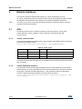
1.3
Resources summary
Table 2 contains the module requirements for the Flash, stack and RAM memories.
Table 2. Resources summary
Omni2
Flash code
stereo (.text)
Omni2 for multichannel
virtualization
8136 Bytes
Omni2 for multichannel
virtualization, 32 bits I/O
8130 Bytes
Flash data
(.rodata)
Stack
Static
RAM
Dynamic
RAM
2064 Bytes
310 Bytes
3100 Bytes
1344 Bytes
The required core frequencies (in MHz) on Table 3 are measured on real HW running on
STM32F407IG chipset, with 10 ms buffers at 48 kHz.
8/26
DocID025072 Rev 4
UM1655
Module overview
Table 3. Frequency requirements (MHz)
Required MHz (for 16 or 32-bit IO)
Mono2Stereo
4.8
2.0 => 2.0 Largely Spaced Speakers
15.5
2.0 => 2.0 Closely Spaced Speakers
17.5
2.0 => 2.0 Very Closely Spaced Speakers
17.5
5.1 => 2.0 Largely Spaced Speakers
25.5
5.1 => 2.0 Closely Spaced Speakers
27.5
5.1 => 2.0 Very Closely Spaced Speakers
27.5
7.1 => 2.0 Largely Spaced Speakers
28
7.1 => 2.0 Closely Spaced Speakers
37
7.1 => 2.0 Very Closely Spaced Speakers
37
DocID025072 Rev 4
9/26
25
Module Interfaces
2
UM1655
Module Interfaces
Two files are needed to integrate this module: lib_omni2_multichannel_m4.a or
lib_omni2_multichannel_32b_m4.a library, and the omni2_glo.h header file which contains
all definitions and structures to be exported to the software integration framework.
Note:
The audio_fw_glo.h file is a generic header file common to all audio modules; it must be
included in the audio framework.
2.1
APIs
Six generic functions have a software interface to the main program: omni2_reset,
omni2_setParam, omni2_getParam, omni2_setConfig, omni2_getConfig, and
omni2_process.
2.1.1
omni2_reset function
This procedure initializes the static memory of the module, and initializes static and dynamic
parameters with default values.
int32_t omni2_reset(void *static_mem_ptr, void *dynamic_mem_ptr);
Table 4. omni2_reset
I/O
Name
Type
Description
Input
static_mem_ptr
void *
Pointer to internal static memory
Input
dynamic_mem_ptr
void *
Pointer to internal dynamic memory
int32_t
Error value
Returned value
−
This routine must be called at least once at initialization time, when the real time processing
has not started.
2.1.2
omni2_setParam function
This procedure writes module static parameters from the main framework to the module's
internal memory. It can be called after the reset routine and before the start of the real time
processing. It handles the static parameters, i.e. the parameters with the values which
cannot be changed during the module processing (frame by frame).
int32_t omni2_setParam(omni2_static_param_t *input_static_param_ptr, void
*static_mem_ptr);
10/26
DocID025072 Rev 4
UM1655
Module Interfaces
Table 5. omni2_setParam
I/O
Name
Type
Description
Input
input_static_param_ptr omni2_static_param_t*
Pointer to static parameters
structure
Input
static_mem_ptr
void *
Pointer to internal static memory
int32_t
Error value
Returned
value
2.1.3
−
omni2_getParam function
This procedure gets the module static parameters from the module's internal memory to the
main framework. It can be called after the reset routine and before the start of the real time
processing. It handles the static parameters, i.e. the parameters with values which cannot
be changed during the module processing (frame by frame).
int32_t omni2_setParam(omni2_static_param_t *input_static_param_ptr, void
*static_mem_ptr);
Table 6. omni2_getParam
I/O
Name
Type
Description
Input
input_static_param_ptr
omni2_static_param_t *
Pointer to static parameters structure
Input
static_mem_ptr
void *
Pointer to internal static memory
int32_t
Error value
Returned
value
2.1.4
−
omni2_setConfig function
This procedure sets the module dynamic parameters from the main framework to the
module internal memory. It can be called at any time during the module processing (after the
reset and setParam routines).
int32_t omni2_setConfig(omni2_dynamic_param_t *input_dynamic_param_ptr,
void *static_mem_ptr);
Table 7. omni2_setConfig
I/O
Name
Type
Description
Input
input_dynamic_param_ptr omni2_dynamic_param_t *
Pointer to dynamic parameters
structure
Input
static_mem_ptr
void *
Pointer to internal static
memory
int32_t
Error value
Returned
value
−
DocID025072 Rev 4
11/26
25
Module Interfaces
2.1.5
UM1655
omni2_getConfig function
This procedure gets the module dynamic parameters from the internal static memory to the
main framework. It can be called at any time during processing (after the reset and
setParam routines).
int32_t omni2_getConfig(omni2_dynamic_param_t *input_dynamic_param_ptr,
void *static_mem_ptr);
Table 8. omni2_getConfig
I/O
Name
Type
Input
input_dynamic_param_ptr
omni2_dynamic_param_t *
Pointer to dynamic parameters structure
Input
static_mem_ptr
void *
Pointer to internal static memory
int32_t
Error value
Returned
value
2.1.6
−
Description
omni2_process function
This procedure is the module's main processing routine. It should be called at any time, to
process each frame.
int32_t omni2_process(buffer_t *input_buffer, buffer_t *output_buffer, void
*static_mem_ptr);
Table 9. omni2_process
I/O
Name
Type
Description
Input
input_buffer
buffer_t *
Pointer to input buffer structure
Output
output_buffer
buffer_t *
Pointer to output buffer structure
Input
static_mem_ptr
void *
Pointer to internal static memory
int32_t
Error value
Returned
value
−
This process routine can run in place only in case of w.x to y.z with (w+x) ≥ (y+z). For
instance, processing such as the stereo widening effect (2.0 to 2.0) or 5.1 virtualization
effect (5.1 to 2.0) can run in place.
2.2
External definitions and types
For genericity reasons and to facilitate the integration in the main frameworks, some types
and definitions have been defined.
2.2.1
Input and output buffers
The library is using extended I/O buffers which contain, in addition to the samples, some
useful information on the stream such as the number of channels, the number of bytes per
sample, and the interleaving mode.
An I/O buffer structure type, as described below, must be followed and filled in by the main
framework before each call to the processing routine:
12/26
DocID025072 Rev 4
UM1655
Module Interfaces
typedef struct {
int32_t
nb_channels;
int32_t
nb_bytes_per_Sample;
void
*data_ptr;
int32_t
buffer_size;
int32_t
mode;
} buffer_t;
Table 10. Input and output buffers
Name
Type
nb_channels
Description
int32_t Number of channels in data: 1 for mono, 2 for stereo
nb_bytes_per_Sample int32_t Dynamic data in number of bytes (2 for 16-bit data, …)
data_ptr
void *
buffer_size
int32_t Number of samples per channel in the data buffer
mode
int32_t Buffer mode: 0 = not interleaved, 1 = interleaved
2.2.2
Pointer to data buffer (must be allocated by the main framework)
Returned error values
Possible returned error values are described below:
Table 11. Returned error values
Definition
Value
Description
OMNI2_ERROR_NONE
0
OK - No error detected
OMNI2_ERROR
-1
Could be a bad sampling frequency, or a bad
dynamic memory allocation
OMNI2_ERROR_PARSE_COMMAND
-2
Internal error - covers bad internal settings
OMNI2_BAD_HW
-3
May happen if the library is not used with the
right hardware
2.3
Static parameters structure
Some static parameters must be set before calling the processing routine.
struct omni2_static_param {
int32_t
Omni2CentreOutput;
int32_t
AudioMode;
int32_t
SamplingFreq;
};
typedef struct omni2_static_param omni2_static_param_t;
DocID025072 Rev 4
13/26
25
Module Interfaces
UM1655
Table 12. Static parameters structure
Name
Type
Description
Omni2CentreOutput
int32_t
0 to disable the center output (for 3.0), 1 to enable the center output (3.0)
AudioMode
int32_t
Can be one field of the eAcMode_Supported enumeration described below; it
is used to describe the input data format
SamplingFreq
int32_t
I/O sampling frequency in Hz
The audio modes available are described below:
enum eAcMode_Supported
{
AMODE20t = 0x0,/*
AMODE10 = 0x1,/*
Stereo channels for dolby pro logic */
Mono channel (1.0) */
AMODE20 = 0x2, /*
Stereo channels (2.0) */
AMODE30 = 0x3, /*
Stereo + Center channel (3.0) */
AMODE32 = 0x7, /*
Stereo + Center channel + Surround Channels (5.0) */
AMODE34 = 0xB,/* Stereo + Center channel + Surround Channels + Center
Surround Channels (7.0) */
AMODE20t_LFE = 0x80,/*
channel */
Stereo channels for dolby pro logic + LFE
AMODE20_LFE = 0x82,/*
Stereo + LFE channel (2.1) */
AMODE30_LFE = 0x83,/*
Stereo + Center channel + LFE channel (3.1) */
AMODE32_LFE = 0x87,/*
Channels (5.1) */
Stereo + Center channel + LFE channel + Surround
AMODE34_LFE = 0x8B,/* Stereo + Center channel + LFE channel + Surround
Channels + Center Surround Channels (7.1) */
AMODE_ID
= 0xFF/*
End of supported configurations */
};
2.4
Dynamic parameters structure
Three dynamic parameters can be used.
struct omni2_dynamic_param {
int32_t
Omni2Enable;
int32_t
Omni2Strength;
int32_t
Omni2ListenigAngle;
};
typedef struct omni2_dynamic_param omni2_dynamic_param_t;
14/26
DocID025072 Rev 4
UM1655
Module Interfaces
Table 13. Dynamic parameters structure
Name
Type
Description
Omni2Enable
int32_t 1 to enable the effect, 0 to disable the effect
Omni2Strength
int32_t
Used to widen front signals from multichannel and stereo inputs. The value
is from 0% (no widening perception) to 100% (maximum widening
perception)
int32_t
Can be OMNI2_LISTENING_ANGLE_10 to have optimal effect with 10
degrees listening angle, OMNI2_LISTENING_ANGLE_20 to have optimal
effect with 20 degrees listening angle and OMNI2_LISTENING_ANGLE_30
to have optimal effect with 30 degrees listening angle
Omni2ListeningAngle
DocID025072 Rev 4
15/26
25
Algorithm description
UM1655
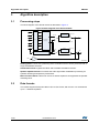
3
Algorithm description
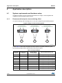
3.1
Processing steps
The block diagram of the Omni2 module is described in Figure 4.
Figure 4. Block diagram of the Omni2 module
>
>
Z
Z
>Ɛ
>Ɛ
ZƐ
ZŽƵƚŝŶŐ
ZƐ
Ɛů
Ɛů
Ɛƌ
Ɛƌ
>
EŽƚŵŽŶŽ
^ƉĞĂŬĞƌ
ĂĚũƵƐƚŵĞŶƚĨŝůƚĞƌ
^ƉĞĂŬĞƌŵŽĚĞ
>
sŝƌƚƵĂůŝnjĂƚŝŽŶ
ƉƌŽĐĞƐƐŝŶŐ
Z
DŽŶŽ
DϮ^ŵŽĚĞ
^ƉĞĂŬĞƌŵŽĚĞ
>
EŽƚŵŽŶŽ
^ƉĞĂŬĞƌ
ĂĚũƵƐƚŵĞŶƚĨŝůƚĞƌ
Z
DŽŶŽͲƚŽͲƐƚĞƌĞŽĞdžƉĂŶƐŝŽŶ
Z
>&
DŽŶŽ
DϮ^ŵŽĚĞ
Ϭ͘ϱ
D^ϯϮϯϱϮsϭ
Routing block: Carries out a premixing of the channels so that it can be processed with a
single virtualization structure.
Virtualization block: Applies the HRTF and Crosstalk cancellation function.
Speaker adjustment filter: Processes the audio signal after virtualization processing for
speaker rendering and spectrum preservation.
Mono-to-stereo block: Carries out a mono-to-stereo expansion and bypasses the speaker
rendering block.
3.2
Data formats
The module supports fixed point data in Q15 or Q31 format, with a mono or a multichannel
up to 7.1 interleaved pattern.
16/26
DocID025072 Rev 4
UM1655
3.3
Algorithm description
Performance assessment
There is no objective measurement available for this module; performances are only based
on a subjective assessment.
Below a list of subjective indicators that could be used to evaluate the effect quality:
Note:
•
Balance between Left Front and Right Front: capacity not to change energy on one
front channel as compared to the other.
•
Balance between Left Surround and Right Surround: capacity not to change energy
on one surround channel as compared to the other.
•
Stereo Widening: ability to increase the audio perception angle to widen the stereo
signal.
•
Distinction between front and side surround channels
•
Center image stability: ability to keep the center image at the center loudspeaker, or
between the left and right front loudspeakers.
•
Sensitivity to sweet spot: ability to feel a widening or surround effect moving away
from the sweet spot described in Section 4.1.1 and Section 4.1.2.
•
Spectrum preservation: ability to keep the original spectrum perception, wherever the
virtual sound comes from.
For more information on the performance, refer to Section 4.1: System requirements and
hardware setup and Section 5: How to run and tune the application.
DocID025072 Rev 4
17/26
25
Application description
UM1655
4
Application description
4.1
System requirements and hardware setup
The library is built to run on a Cortex M4 core without FPU usage. It was integrated and
validated on some STM32F4 family devices.
4.1.1
Recommended setup for stereo widening effect
The stereo widening effect is designed for 10, 20 and 30 degrees typical listening angles,.
Figure 5. Setup for stereo widening effect
3K\VLFDO6SHDNHUV
/DUJHO\6SDFHG6SHDNHUV
3K\VLFDO6SHDNHUV
&ORVHO\6SDFHG6SHDNHUV
'HJ
3K\VLFDO6SHDNHUV
9HU\&ORVHO\6SDFHG6SHDNHUV
'HJ
'HJ
06Y9
Find in Table 14 some setup examples and direct impacts on speaker distance to get a
typical listening angle and an optimal stereo widening perception.
Table 14. Setup examples
Inter Speaker Speaker/Listener
Distance
Distance
18/26
Corresponding
Listening Angle
Recommended mode to use
0.3 m
2.5 m
7
OMNI2_LISTENING_ANGLE_10
0.3 m
1.8 m
10
OMNI2_LISTENING_ANGLE_10
0.3 m
1.2 m
14
OMNI2_LISTENING_ANGLE_10
0.3 m
0.6 m
28
OMNI2_LISTENING_ANGLE_30
0.4 m
2.5 m
9
OMNI2_LISTENING_ANGLE_10
0.4 m
1.8 m
13
OMNI2_LISTENING_ANGLE_10
0.4 m
1.2 m
19
OMNI2_LISTENING_ANGLE_20
0.4 m
0.6 m
37
OMNI2_LISTENING_ANGLE_30
0.6 m
2.5 m
14
OMNI2_LISTENING_ANGLE_10
DocID025072 Rev 4
UM1655
Application description
Table 14. Setup examples (continued)
Inter Speaker Speaker/Listener
Distance
Distance
Corresponding
Listening Angle
Recommended mode to use
0.6 m
1.8 m
19
OMNI2_LISTENING_ANGLE_20
0.6 m
1.2 m
28
OMNI2_LISTENING_ANGLE_30
0.8 m
2.5 m
18
OMNI2_LISTENING_ANGLE_20
0.8 m
1.8 m
25
OMNI2_LISTENING_ANGLE_20 or
OMNI2_LISTENING_ANGLE_30
0.8 m
1.2 m
37
OMNI2_LISTENING_ANGLE_30
1.0 m
2.5 m
23
OMNI2_LISTENING_ANGLE_20
1.0 m
1.8 m
31
OMNI2_LISTENING_ANGLE_30
1.2 m
2.5 m
27
OMNI2_LISTENING_ANGLE_30
1.2 m
1.8 m
37
OMNI2_LISTENING_ANGLE_30
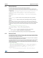
It must be noted that the listener must be well centered between the two loudspeakers in
order to benefit from the stereo widening effect because this effect is very sensitive to lateral
sweet spot.
Listening angle below 20 degrees could correspond to a typical TV watching with down
firing speakers, small sound bars or docking stations usage.
Positions of the virtual front channels should vary from ±15˚ to ±50˚.
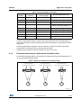
4.1.2
Recommended setup for multichannel virtualizer effect
Like the Stereo Widening effect, the multichannel virtualizer effect has been designed for 10,
20 and 30 degrees listening angles.
Figure 6. Setup for multichannel virtualizer effect
3K\VLFDO6SHDNHUV
/DUJHO\6SDFHG6SHDNHUV
'HJ
3K\VLFDO6SHDNHUV
&ORVHO\6SDFHG6SHDNHUV
'HJ
3K\VLFDO6SHDNHUV
9HU\&ORVHO\6SDFHG6SHDNHUV
'HJ
06Y9
DocID025072 Rev 4
19/26
25
Application description
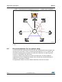
UM1655
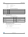
Table 15. Virtualized sound compliant with ITU-T 7.1 speaker layout standards
3K\VLFDO6SHDNHUV
'HJ
'HJ
'HJ
3HUFHLYHG9LUWXDO6SHDNHUV
069
i.e. Front channels are at ± 30°, Side channels are at ± 110° and Rear channels are at
± 150°.
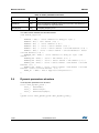
4.2
Recommendations for an optimal setup
The library processing should be placed just after the multichannel decoder and before the
sampling rate conversion in order to process the audio signal at 32, 44.1 or 48 kHz, and
avoid doing sampling rate conversions on multichannel. Note that only 48kHz sampling
frequency is supported in this SW version.
There is no need for this module to be close to the audio DAC, and some graphical
equalizer and volume management modules can be placed after it without affecting the
widening or virtualization perception.
To integrate this module in an audio software framework, follow the next steps.
20/26
DocID025072 Rev 4
UM1655
4.2.1
Application description
Memory allocation
First of all, all the memory used by the module must be allocated.
The static parameters structure and dynamic parameters structure are exported in the
omni2_glo.h file, so that the memory for these structures can be allocated as written in the
example below:
/* Omni2 static and dynamic parameters structures memory allocation */
omni2_static_param_t *static_param_ptr = malloc(sizeof(omni2_static_
param_t)));
omni2_dynamic_param_t *dynamic_param_ptr = malloc(sizeof(omni2_dynamic_
param_t)));
Where:
static_param_ptr pointer is used by omni2_setParam() and omni2_getParam()
routines.
dynamic_param_ptr pointer is used by omni2_setConfig() and omni2_getConfig()
routines.
Next, the static and dynamic memory required by the module must be allocated by the
framework. Structures are hidden to the audio framework, but their sizes are exported as a
constant in the omni2_glo.h file, so that the memory allocation can be done as written
below:
/* Omni2 memory structure memory allocation */
void *static_mem_ptr = malloc(omni2_static_mem_size);
void *dynamic_mem_ptr = malloc(omni2_dynamic_mem_size);
Where:
•
dynamic_mem_ptr pointer is a parameter of the omni2_reset() routine
•
static_mem_ptr pointer is a parameter of all exported APIs.
Then, it is necessary to allocate the memory for the input and output audio buffers.
4.2.2
Module API calls
Once the memory as been allocated, the omni2_reset() routine must be called to initialize
the module's static memory. The omni2_reset() routine must be called each time the audio
processing has been stopped and started.
The omni2_getParam() routine can be called while the run time process has not started to
extract the current static parameters used, if needed.
The static parameters can be set as soon as the input sampling frequency and the stream
information are known. The omni2_setParam() routine must be called to configure the
module's internal memory with the corresponding sampling frequencies and the audio mode
as in the example below:
/* Omni2 static parameters setting */
omni2_static_param.Omni2CentreOutput = 0;/* center output disabled */
omni2_static_param.SamplingFreq = 48000;/* I/O sampling frequency */
omni2_static_param.AudioMode = AMODE32_LFE;/* 5.1 -> 2.0 : 5.1
virtualization */
error = omni2_setParam(&omni2_static_param, omni2_static_mem_ptr);
DocID025072 Rev 4
21/26
25
Application description
UM1655
Now that the hardware has been configured and the module has been initialized and
configured, the run time processing can start.
Every time the dynamic parameters change, they are taken into account by the module
thanks to the omni2_setConfig() routine:
/* Omni2 dynamic parameters setting */
omni2_dynamic_param.Omni2Enable = Omni2CtrlStruct->Omni2Enable;
0 = disable, 1 = enable */
omni2_dynamic_param.Omni2Strength = Omni2CtrlStruct->Omni2Strength;
value from 0 to 100 */
/*
/*
omni2_dynamic_param.Omni2ListeningAngle = Omni2CtrlStruct>Omni2ListeningAngle;
error = omni2_setConfig(&omni2_dynamic_param, omni2_static_mem_ptr);
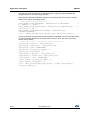
At each new frame, the input buffer structure fields must be filled in as in the example below,
as well as the data address for the output buffer structure. Then, the omni2_process()
routine can be called:
/* Omni2 input buffer configuration and processing all */
input_buffer_t.data_ptr = input_buffer_ptr;
input_buffer_t.buffer_size = input_buffer_size;
input_buffer_t.mode = INTERLEAVED;
input_buffer_t.nb_bytes_per_Sample = 2;
input_buffer_t.nb_channels = 6;
output_buffer_t.data_ptr = output_buffer_ptr;
output_buffer_t. buffer_size = input_buffer_size;
output_buffer_t. mode = INTERLEAVED;
output _buffer_t.nb_bytes_per_Sample = 2;
output _buffer_t.nb_channels = 2;
error = omni2_process(&omni2_input_buffer_t, &omni2_output_buffer_t,
omni2_static_mem_ptr);
22/26
DocID025072 Rev 4
UM1655
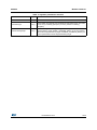
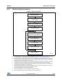
4.2.3
Application description
Module integration summary
Figure 7. API call procedure
0HPRU\DOORFDWLRQ
RPQLBUHVHW
VWDWLFBSDUDPLQLWLDOL]DWLRQ
RPQLBVHW3DUDP
DXGLRVWUHDPUHDG
LQSXWBEXIIHUSUHSDUDWLRQ
RPQLBVHW&RQILJ
RPQLBSURFHVV
$XGLRVWUHDPZULWH
0HPRU\IUHHLQJ
069
1. As explained above, the module 's static and dynamic structures have to be allocated, as well as the input
and output buffer, according to the structures defined in Section 2.2.1: Input and output buffers.
2. Once the memory has been allocated, the call to omni2_reset() function initializes the internal variables.
3. The module's static configuration can now be set by initializing the static_param structure, once the input
sampling frequency and the audio mode are known.
4. Call the omni2_setParam() routine to send the static parameters from the audio framework to the module.
5. The audio stream is read from the proper interface and the input_buffer structure has to be filled in
according to the stream characteristics (number of channels, sample rate, interleaving and data pointer).
The output buffer structure has to be set as well.
6. Get the dynamic parameters when they are updated and call the omni2_setConfig() routine to send the
dynamic parameters from the audio framework to the module.
7. Call the processing main routine to apply the effect.
8. The output audio stream can now be written in the proper interface.
9. Once the processing loop is over, the allocated memory has to be freed.
DocID025072 Rev 4
23/26
25
How to run and tune the application
5
UM1655
How to run and tune the application
Once the module has been integrated into an audio framework to play samples at 48 kHz,
just launch the Audio player and choose a .WAV or .MP3 file with a 48 kHz sampling
frequency if no sampling rate conversion is available.
The Omni2Enable from the module’s dynamic parameters is used to enable and disable the
effect.
The Omni2Strength field is used to change the virtual listening angle. 0% means that virtual
speakers are close to physical speakers, while 100% leads to the widest virtual angle
(typically 100 degrees).
Omni2ListeningAngle field from the module’s dynamic parameters is modified by selecting
between “LargeSpacedS”, “CloseSpacedS” and “VCloseSpacedS”.
24/26
DocID025072 Rev 4
UM1655
6
Revision history
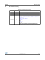
Revision history
Table 16. Document revision history
Date
Revision
26-Aug-2013
1
Initial release.
28-Nov-2014
2
Updated RPN on cover page
10-Dec-2014
3
Updated Section 5.
4
Updated:
– Section 1.1, Section 1.3, Section 2.4, Section 4.1.1, Section 4.2,
Section 4.2.2
– Table 2, Table 3, Table 13
– Figure 5,
Added:
– Table 14
Removed:
– section: “Recommended setup for stereo widening effect for
closely spaced speakers (Omni2DownFiringSpeakers set)”
22-Jul-2015
Changes
DocID025072 Rev 4
25/26
25
IMPORTANT NOTICE – PLEASE READ CAREFULLY
STMicroelectronics NV and its subsidiaries (“ST”) reserve the right to make changes, corrections, enhancements, modifications, and
improvements to ST products and/or to this document at any time without notice. Purchasers should obtain the latest relevant information on
ST products before placing orders. ST products are sold pursuant to ST’s terms and conditions of sale in place at the time of order
acknowledgement.
Purchasers are solely responsible for the choice, selection, and use of ST products and ST assumes no liability for application assistance or
the design of Purchasers’ products.
No license, express or implied, to any intellectual property right is granted by ST herein.
Resale of ST products with provisions different from the information set forth herein shall void any warranty granted by ST for such product.
ST and the ST logo are trademarks of ST. All other product or service names are the property of their respective owners.
Information in this document supersedes and replaces information previously supplied in any prior versions of this document.
© 2015 STMicroelectronics – All rights reserved
26/26
DocID025072 Rev 4