1
AXIS AX-7 Cobra+
Technical Reference
PREFACE
Please refer to the User’s Manual for installation and basic configuration procedures.
Every care has been taken in the preparation of this manual; if you detect any
inaccuracies or omissions, please inform us at the address supplied.
Axis Communications AB cannot be held responsible for any technical or
typographical errors and reserves the right to make changes in this manual and to the
firmware without prior notice.
About Axis
Axis Communications, founded in 1984, is one of the world’s fastest growing
companies in the printer interface, network print server and CD-ROM server market.
The head quarters are located in Lund, Sweden, with subsidiaries in Beijing, Shanghai,
Singapore, Tokyo, Hong Kong and Paris. Please refer to How to contact Axis on page
163.
Axis Communications has a distributor network operating in more than 60 countries
world-wide, marketing four product lines:
IBM Mainframe S/3x and AS/400 Printer Interfaces - These products include a
wide range of plug-in interfaces and free standing box products such as the Cobra+ and
the AFP IPDS-to-PostScript converter.
Network Print Servers - These intelligent Ethernet and Token Ring print servers
support a wide range of LAN protocols. The AXIS NPS 530, 532, 550 and AXIS 150,
152, 540, 542, 560, 570 are Ethernet print servers, while the Axis NPS 630, 632, 650
and AXIS 640, 642, 660, 670 are Token Ring print servers.
CD-ROM Servers - Multiprotocol CD-ROM servers provide a flexible and
cost-efficient solution for sharing CD-ROMs across the network. They are available in
Ethernet and Token Ring versions.
Network Camera Server - The AXIS Neteye 200 Network Camera attaches directly
to an Ethernet network. It supports TCP/IP and Internet-related protocols. This product
replaces closed circuit video or PC with framegrabber, at a lower cost.
ABOUT THIS MANUAL
This manual contains a detailed technical description of the Axis protocol converters
and how to use them in an IBM printing environment. The protocol converters covered
belong to the Cobra family, they are:
AX-7 Cobra+, AXIS OKI HD, AX-4039/1, AXIS COBRA+ OEM and the AXIS 370
Cobra.
If you are not familiar with the basic functions of the protocol converters, refer to the
User’s Manual.
Axis AX-7 Cobra+ Technical Reference
2
The sections and appendices of this manual cover the following topics:
• THE IBM 3270 ENVIRONMENT
Describes the SNA and BSC communication methods, and how the protocol
converter exchanges information with the IBM system.
• IBM 3270 CONTROL CODES
Describes the LU-1 (SCS) and DSC/DSE Control Codes supported by the protocol
converters.
• THEORY OF OPERATION
Contains a functional description of the protocol converter.
• EXTENDED EMULATION MODE
Configuration methods, Hex Transparency, advanced printer control, and bar codes.
• PC-HOST SHARING
Using the same printer for both host and PC printouts.
• AUTOMATIC ORIENTATION AND COR
Automatic adaptation of print orientation and scaling to the printer paper size.
• SOLVING PROBLEMS
How to solve common problems.
• PRINTER DRIVERS
A list of supported printer drivers.
• THE PARAMETER LIST
A complete description of all parameters.
• INTERNAL FUNCTIONS
Describes the functions available in the Extended Emulation Mode.
• CHARACTER TABLES
National dependent EBCDIC tables and International Set 5.
• IBM RPQs
• FRONT PANEL
• COMPATIBILITY WITH OTHER PRODUCTS
• USING THE MD-GRAFTEXT SOFTWARE
• CABLES
• UPGRADING FIRMWARE
• TEXHNICAL SPECIFICATIONS
• RELATED SPECIFICATIONS
• HOW TO CONTACT AXIS
• GLOSSARY
• INDEX
Axis AX-7 Cobra+ Technical Reference
3
EMISSION NOTICES
USA
This equipment generates, uses, and can radiate radio frequency energy and if not
installed and used in accordance with the instruction manual, may cause interference to
radio communications. It has been tested and found to comply with the limits for a
Class A computing device pursuant to Subpart B of Part 15 of FCC rules, which are
designed to provide reasonable protection against such interference when operated in a
commercial environment. Operation of this equipment in a residential area is likely to
cause interference in which case the user at his own expense will be required to take
whatever measures may be required to correct the interference. Shielded cables should
be used with this unit to ensure compliance with the Class A limits.
Europe
This digital equipment fulfils the requirements for radiated emission according to limit
B of EN55022/1987, and the requirements for immunity according to EN50082-1/1992
residential, commercial, and light industry. (Compliance is not valid for unshielded
network and printer cables.)
TRADEMARK ACKNOWLEDGEMENTS
IBM, Epson, Fujitsu, OKI Diablo, Philips, Mannesmann, Brother, Hewlett-Packard,
LaserJet, Cannon, Xerox, are registered trademarks of the respective holders.
AX-7 Cobra+ Technical Reference
Revision: 6.0
Part No: 12937
Dated: February, 1997
Copyright © Axis Communications AB, 1992–1997
Axis AX-7 Cobra+ Technical Reference
4
TABLE OF CONTENTS
CONTENTS
Section 1
THE IBM 3270 ENVIRONMENT
Copy Controls
Communication Methods
The Communications Buffer
The Printer Control Information Area (PCIA)
The Printer Output Area
3270 Host Configuration
7
7
8
9
10
10
15
Section 2
IBM 3270 CONTROL CODES
DSC/DSE Base Buffer Attributes
DSC/DSE Extended Attributes
DSC/DSE Control Codes
16
17
18
19
Section 3
THEORY OF OPERATION
Data Flow Chart
Protocol Converters Data Processing Control
29
29
31
Section 4
EXTENDED EMULATION MODE
Using Extended Emulation Mode
Extended Emulation Mode Types
Configuration from the System
Hex Transparency
Redefinition of Lead-in and Trailer Sequences
Modifying the Character Translation Tables
User Definable Strings
String Substitutions
32
33
36
37
39
44
45
49
50
Section 5
PC-HOST SHARING
Using an External Printer Sharing Device
54
55
Section 6
AUTOMATIC ORIENTATION AND COR
56
Section 7
SOLVING PROBLEMS
Missing Printouts
Incorrect Host Printouts
Error Messages
57
57
58
61
Section 8
PRINTER DRIVERS
62
Section 9
THE PARAMETER LIST
64
Section 10
INTERNAL FUNCTIONS
106
Section 11
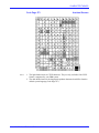
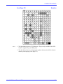
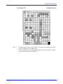
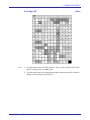
CHARACTER TABLES
115
Axis AX-7 Cobra+ Technical Reference
5
TABLE OF CONTENTS
APPENDIX A
IBM RPQs
Carriage Return at MPP+1
New Line at MPP+1
Form Feed within the Print Buffer
Null Suppression
Valid Form Feed Positions
Automatic Function at End of Job
Automatic Function at End of Operator Initiated Local Copy
136
136
136
137
137
137
138
138
APPENDIX B
THE FRONT PANEL
The POWER indicator
The SYSTEM indicator
The PC SHARE indicator
The Rotary Switch
139
139
139
139
140
APPENDIX C
COMPATIBILITY WITH OTHER PRODUCTS
Agile (6287 Ultra)
Andrew (Malibu)
Avatar (MainPrint CG)
I-Data (IDA 3270)
Memorex 2068
MPI (AT 02)
141
142
142
143
143
144
145
APPENDIX D
USING THE MD-GRAFTEXT SOFTWARE
146
APPENDIX E
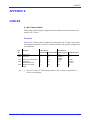
CABLES
Overview
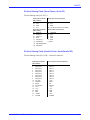
Centronics Parallel Printer Cable
RS-232 Serial Printer Cable
PC-Host Sharing Cable (Serial Printer, Serial PC)
PC-Host Sharing Cable (Parallel Printer, Serial/Parallel PC)
PC-Host Sharing Cable (Parallel Printer, Parallel PC)
Power Connector
147
147
148
148
149
149
151
155
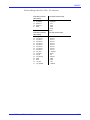
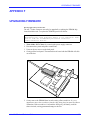
APPENDIX F
UPGRADING FIRMWARE
Dip Switch Positions
Updating the software
156
157
157
APPENDIX G
TECHNICAL SPECIFICATIONS
159
APPENDIX H
RELATED DOCUMENTATION
162
HOW TO CONTACT AXIS
Axis on-line service
163
163
APPENDIX I
Axis AX-7 Cobra+ Technical Reference
6
THE IBM 3270 ENVIRONMENT
SECTION 1
THE IBM 3270 ENVIRONMENT
This section describes the IBM environment in which the protocol converter is
intended to operate in. For further details, refer to the documents listed in Appendix H.
Copy Controls
There are three different operations that can cause the protocol converter to start a print
operation:
• Host Directed Copy: The host sends print data directly to the protocol converter
(normal print operation).
• Host Initiated Local Copy: The host sends the information displayed on a terminal
to the protocol converter. This operation is activated by pressing the ‘Print Screen’
function key set up by the application.
• Operator Initiated Local Copy: The display station operator sends the
information displayed on a terminal to the protocol converter by pressing the ‘Local
copy’ key (application independent).
Axis AX-7 Cobra+ Technical Reference
7
THE IBM 3270 ENVIRONMENT
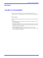
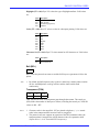
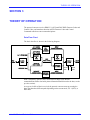
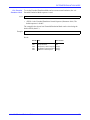
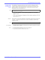
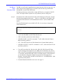
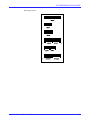
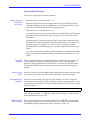
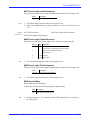
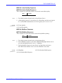
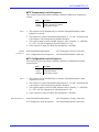
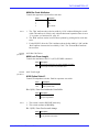
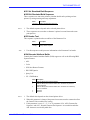
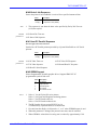
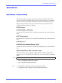
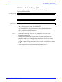
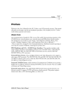
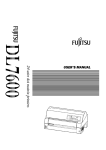
Communication Methods
The protocol converter communicates with the IBM 3270 environment through a 3x74
Control Unit using either SNA (System Network Architecture) or non-SNA (Binary
Synchronous Communication, BSC) as shown in the diagram below.
Host
Host
SNA
(SDLC or
channel)
3x74
Control Unit
3x74
Control Unit
LU-3
(DSE)
non-SNA
(BSC or
channel)
LU-1
(SCS)
AX-7 Cobra+ AX-7 Cobra+
LU-0
(DSC)
AX-7 Cobra+
System Network
Architecture
The two SNA modes of communication are LU-1 and LU-3. LU-1 is the SCS (SNA
Character String) mode, and uses EBCDIC Character Sets, 118 onwards. LU-3 is the
DSE (Data Stream Emulation) mode and uses DBC Character sets, see page 116 and
117. DSE is the SNA equivalent to the DSC mode described below.
Binary
Synchronous
Communication
BSC has only one communication mode, which is DSC (Data Stream Compatible)
mode. It uses DBC Character Sets, see page 116 and 117. In a BSC environment, all
copy control operations use the same mode of communication.
Axis AX-7 Cobra+ Technical Reference
8
THE IBM 3270 ENVIRONMENT
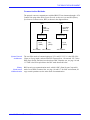
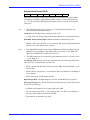
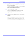
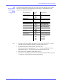
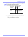
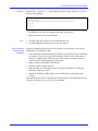
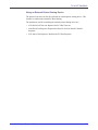
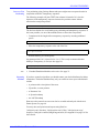
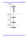
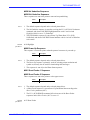
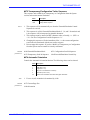
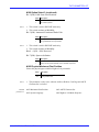
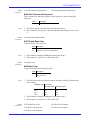
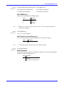
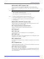
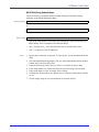
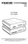
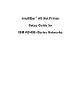
The Communications Buffer
The protocol converter has an 8K storage area called the communications buffer. This
buffer is a temporary storage for coax data, commands, and the controls necessary for
the protocol converter operation.
The communications buffer contains a character buffer (also called the base buffer),
and an extended attribute buffer (EAB) of 4K each. The first 80 bytes of the character
buffer is the Printer Control Information Area (PCIA), and the first 80 bytes of the
EAB is the extended PCIA.
The remainder of the character buffer is the message area, containing buffers of print
data. The EAB contains additional information about how each character should be
printed, see page 18
PCIA
Character Buffer
Ext. PCIA
Extended Attribute
Buffer (EAB)
The communications buffer.
Axis AX-7 Cobra+ Technical Reference
9
THE IBM 3270 ENVIRONMENT
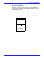
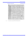
The Printer Control Information Area (PCIA)
The PCIA is the first 80 bytes of the character buffer. The first 16 bytes (addresses
$0000 to $000F) is the Printer Output Area, which informs the host about the printer
type and supported features.
The rest of the PCIA (addresses $0010 to $004F) is the Host Output Area, which
informs the printer about the character buffer and EAB print data.
The following tables list the PCIA addresses, their functions, and a description of each
bit or code. To view the contents of the PCIA, you can perform a system hex dump, see
page 60
Note:
1. The bits are numbered as in the IBM documentation, i.e. bit 0 is the most
significant, and bit 7 is the least significant.
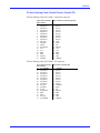
The Printer Output Area
Address
Function Bit/Code
Description
$0000
Status
Register
Bit 0
0 - Address $0006 is reserved
1 - Address $0006 contains extended status
Bit 1
Bit 2
Bit 3
Bit 4
Bit 5
Bit 6
Bit 7
Bit 0 - 2
Bit 3
Bit 4
Data check
Order complete
Equipment check (hardware or PCIA error)
Operator intervention required
Sense data available (see address $0003)
Input code available (see address $0002)
Valid switch transition (see address $0001)
Reserved
0
0
Bit 5
0 - Monocase
1 - Dual Case
Bit 6
0 - Single line spacing
1 - Double line spacing
Bit 7
0 - 6 lines per inch
1 - 8 lines per inch
Attention (PA1 or PA2 pressed in receive state)
PA1 key pressed
PA2 key pressed
No PA key pressed
Inbound data available
DSC/DSE query reply (partial)
DSC/DSE query reply (complete)
LU-1 inbound data without FM header
$0001
$0002
Axis AX-7 Cobra+ Technical Reference
Switch
Status
Switch
Input
Code
Code $50
Code $5F
Code $5E
Code $5D
Code $6B
Code $6C
Code $6D
Code $6F
10
THE IBM 3270 ENVIRONMENT
Address
Function
Bit/Code
Description
$0003
Sense
Data
$0004 to
$0005
Inbound
Message
Length
Extended
Status
Code $01
Code $02
Code $03
Code $04
Code $05
Code $06
Code $07
Code $08
-
Cancel key pressed (LU-1 mode)
Invalid control code parameter
Invalid LU-1 (SCS) Control code
Order reject
Invalid PS selection
Invalid LCID selection
Invalid FM header
Invalid structured field (DSC mode)
-
Bit 0 - 6
Reserved
Bit 7
0 - Order complete (not deferred)
1 - Order complete (deferred)
-
$0006
$0007 to
$0009
$000A
Reserved -
$000B
Printer
Type and
Character
Set
$000C
Features
$000D
Axis AX-7 Cobra+ Technical Reference
Features
Bit 0
Bit 1
Bit 2
Bit 3
Bit 4 - 5
Bit 6
Bit 7
Bit 0 - 3
Underline supported
Reverse video supported (not applicable)
Blink supported (not applicable)
Translate table required
Reserved
Save/Restore and Query List supported
DSC/DSE Query supported
0000 - Old Type (i.e. 4214)
0001 - ADII 3287 or equivalent
0010 - 4250 or equivalent
0100 - 3268 or equivalent
0101 - 3230 or equivalent
0111 - 3262 or equivalent
1001 - 5210 or equivalent
Bit 4 - 7
Bit 0
Bit 1
Bit 2
Bit 3
0000 - APL (All other codes are reserved)
Extended Attribute Buffer (EAB) installed
APL/Text installed (requires EAB)
PS installed (requires EAB)
SCS EBCDIC installed (always 1)
Bit 4 - 6
001 - Screen size = 960 bytes
010 - Screen size = 1920 bytes
011 - Screen size = 2560 bytes
110 - Screen size = 3564 bytes
111 - Screen size = 3440 bytes
Bit 7
Unit ID (always 1)
Character Code $08 2 K base buffer (not including EAB)
Buffer
Code $10 4 K base buffer (not including EAB)
Size
Code $20 8 K base buffer (not including EAB)
11
THE IBM 3270 ENVIRONMENT
Address
Function
Bit/Code
Description
$000E
Extended
ID
$000F
Prog.
Symbols
Bit 0 - 1
Bit 2
Bit 3
Bit 4
Bit 5
Bit 6-7
Bit 0 -1
Reserved
Color supported
LU-1 FM header supported (always 1)
Load Structured Field order supported
CECP supported
Reserved
00 - No PS installed
01 - 2 PS installed (2 - 3)
10 - 4 PS installed (2 - 5)
11 - 6 PS installed (2 - 7)
Bit 2 - 7
1xxxxx - triplane installed on PS no. 2
x1xxxx - triplane installed on PS no. 3
xx1xxx - triplane installed on PS no. 4
xxx1xx - triplane installed on PS no. 5
xxxx1x - triplane installed on PS no. 6
xxxxx1 - triplane installed on PS no. 7
The Host Output
Area
Address Function Bit/Code
Description
$0010
Reserved
Enable Set Attribute (SA) LU-1 control code
Mode (1) Bit 0 - 4
Bit 5
Bit 6 -7
$0011
$0012 to
$0013
Mode (2) Bit 0 - 2
Bit 3 - 4
00 - Host Directed Copy
01 - Host Initiated Local Copy
10 - Operator Initiated Local Copy
11 - Reserved
Bit 5 -7
000 - No mode
001 - Data stream Compatible Mode (DSC)
101 - Data stream Emulation Mode (SNA - DSE)
110 - LU-1 (SCS) mode
(All other codes are reserved)
These bytes define the character buffer address
where the current message begins.
$0014 to
$0015
Message (MSA)
Starting
Address
Message (ML)
Length
$0016
Order
Axis AX-7 Cobra+ Technical Reference
00 - Use the Base Color switch setting
01 - Disable Base Color (override switch setting)
10 - Enable Base Color (override switch setting)
11 - Reserved
Reserved
Code $01
Code $02
Code $03
Code $04
Code $05
Code $06
Code $07
These bytes define the length of the current
message. If the length is zero, nothing is printed.
In LU-1 mode, data will wrap from the end of the
character buffer to address $0050. In DSC/DSE
modes, no wrapping occurs.
Abort
System Status Available
Print/FM Header Processing
DSC/DSE Load PS
Load Translate Table
DSC/DSE Query
DSC Load Structured Field
12
THE IBM 3270 ENVIRONMENT
Address Function
$0017
Bit/Code
Description
LU-1 mode
Order
Parameters
Abort
Bit 0 - 7
System
Status
Available
Code $00 Mode change
Code $02 Enter send state
Code $03 Enter receive state
Print/FM
Header
Processing
Bit 0
0 -Extended Order parameter not used
1 -Extended Order parameter (see addr. $0022)
Bit 1
0 -Not first segment of first-in-chain
1 -First segment of first-in-chain
Bit 2
0 -Not last segment of first-in-chain
1 -Last segment of first-in-chain
Bit 3
0 -EBCDIC data code
1 -Reserved
Bit 4 - 6
Reserved
Bit 7
0 -SCS data stream
1 -FM Header data stream
Reserved
Load
Translate
Table
DSC/DSE
The bits have different meanings for different orders
Bit 0 - 7
The bits have different meanings for different
mode order
Parameters
Print
Reserved
orders:
Bit 0
Reserved
Bit 1
0 -Data is in DBC Base Character code
1 -Data is in DBC CECP Character code
Bit 2
Reserved
Bit 3
0 -Control Codes $01 - $07 are valid regardless
of the EAB byte value.
1 -Control Codes $01 - $07 are valid only if the
Bit 4
Axis AX-7 Cobra+ Technical Reference
EAB byte value equals xxxxx001 (APL).
0 -Print without the EAB
1 -Print with the EAB
Bit 5 - 6
00 - Use default for Mono/Dual case
01 - Monocase
10 - Dual case
11 - Reserved
Bit 7
0 - Unformatted mode (honor NL, EM, and CR)
1 - Formatted mode (ignore NL, EM, and CR)
13
THE IBM 3270 ENVIRONMENT
Address Function
Bit/Code
Load PS
$0017
Reserved
Bit 1
0 -Continuation of Load PS order
1 -Beginning of Load PS order
Bit 0
Load
Translate
Table
DSC/DSE
Query
Description
Bit 2 - 7
Bit 0 - 7
Reserved
Reserved
Bit 0
Reserved
Bit 1
0 -Continuation of query
1 -Beginning of query
Bit 2 - 7
Load Struct. Field Bit 0 - 7
Reserved
Reserved
Address Function Bit/Code
Description
$0018
This byte specifies the MPP for DSC/DSE
modes. If zero, the default MPP setting is used.
Maximum Print
Position
$0019 to Reserved $0021
$0022
Extended Bit 0
Order
Bit 1
Reserved
0 - Continue on error. Any unsupported LU-1
control code causes a hyphen to be printed.
1 - Stop on error. Any unsupported LU-1
control code causes a “Function not
Bit 2 - 7
$0023 to
$002F
$0030
$0031
$0032
$0033
$0034
$0035
$0036
$0037
$0038
$0039
$003A
$003B
$003C
$003D
$003E
$003F
$0040 to
$0049
$004A to
$004D
$004E to
$004F
Axis AX-7 Cobra+ Technical Reference
supported” to the host.
Reserved
Reserved
Code $00
Code $00
Code $F1
Code $00
Value
Value
Value
Value
Value
Value
Value
Value
Value
Value
Value
Value
Reserved -
Non-loadable character set (always $00)
Test
Message
Reserved -
Test message from the Control Unit:
e.g. $AA $32 $74 $AA (for 3274)
-
LCID
Table
APL character set (if installed)
LCID for PS 2
APA value for PS 2
LCID for PS 3
APA value for PS 3
LCID for PS 4
APA value for PS 4
LCID for PS 5
APA value for PS 5
LCID for PS 6
APA value for PS 6
LCID for PS 7
APA value for PS 7
-
14
THE IBM 3270 ENVIRONMENT
3270 Host Configuration
The protocol converter supports non-SNA (LU-0) 3270 DSC, SNA LU-3 3270 DSE,
and SNA LU-1 SCS data streams.
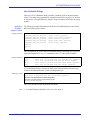
When printing in an SNA network, VTAM needs to be set up, depending on desired
LU type. The following VTAM logon-mode entries apply to MVS, VM, and VSE.
The logon-mode entries are the same for all emulated IBM printers (selected by the
protocol converter IBM Printer Emulation parameter).
SNA LU-1 SCS:
SCS
MODEENT LOGMODE=SCS,FMPROF=X'03',TSPROF=X'03',PRIPROT=X'B1',
SECPROT=X'90',COMPROT=X'3080',RUSIZES=X'87C6',
PSERVIC=X'01000000E100000000000000',
PSNDPAC=X'01',SRCVPAC=X'01'
SNA LU-3 3270 DSE:
DSC4K
MODEENT
Note:
LOGMODE=DSC4K,FMPROF=X'03’,TSPROF=X'03',PRIPROT=X'B1',
SECPROT=X'90',COMPROT=X'3080',RUSIZES=X'8787',
PSERVIC=X'03000000000018502B507F00'
1. Continuation characters in column 72 are not shown
You also need to match the Printer Emulation setting in protocol converter with the
setting of your 3270 printer driver software (JES/328x, VPS, CMA-Spool, RSCS, etc.).
Axis AX-7 Cobra+ Technical Reference
15
IBM 3270 CONTROL CODES
SECTION 2
IBM 3270 CONTROL CODES
This section describes the emulation of IBM control codes in DSC/DSE and LU-1
(SCS) communication modes.
Control codes are the IBM 3270 equivalent to ASCII escape sequences. The LU-1
(SCS) mode has a large number of control codes, but the DSC/DSE mode supports
only a few. Instead, print control is obtained by PCIA settings, base buffer attributes,
and extended attributes.
See page 10 for an explanation of the PCIA settings.
Base buffer attributes appear in the Character Buffer, see page 9. They apply to all subsequent character and control codes.
Extended attributes appear in the Extended Attribute Buffer. An extended attribute
applies only to the character or control code in the corresponding Character Buffer
position. Extended attributes can only be used when the EAB function is enabled.
Note:
1. The DSC/DSE data stream is created by the control unit from the 3270 data stream
sent from the host, see page 8.
Axis AX-7 Cobra+ Technical Reference
16
IBM 3270 CONTROL CODES
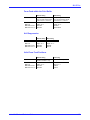
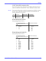
DSC/DSE Base Buffer Attributes
All codes from $C0 and above are base buffer attributes. A base buffer attribute controls the interpretation of all subsequent character and control codes until cancelled by
another base buffer attribute.
The attribute itself is treated as null, i.e. it prints as a space in unformatted mode.
The table below explains the meaning of the base buffer attribute bits (bit 7 is the most
significant, and bit 0 is the least significant):
Bit
Description
7
6
5
Always 1
Always 1
0 - Unprotected field
1 - Protected field
4
0 - Alphanumeric field
1 - Numeric field
3 - 2 00 - Normal (print) field
01 - Normal (print) field
10 - Intensified (print) field
11 - Invisible (non-print) field
1
Reserved
0
Reserved
• Protected/unprotected: This is a screen attribute. It affects printing in color mode
only, see Highlight (parameter #019), see page 71.
• Numeric/alphanumeric: This is a screen attribute, it does not affect printing.
• Normal: Cancels an Intensified or Invisible attribute.
• Intensified: Prints as highlighted as determined by Highlight (parameter #019) see
page 71.
• Invisible (non-print): Character and control codes are treated as nulls.
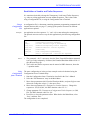
Base Buffer Attributes Printed color
Base Color: Black enabled Base Color: Green enabled
Unprotected, Normal
Unprotected, Intensified
Protected, Normal
Protected, Intensified
Black
Red
Blue
Green
Green
Red
Blue
Black
This table shows the resulting print color for different base buffer attribute and base
color combinations. See page 96, Base Color (parameter #128) for further details on
base color settings.
All colors are printed as black on monochrome printers. You may substitute color with
highlight features such as underscoring or bolding by programming the appropriate
color sequences.
The following example assumes that the Red Color Sequence (parameter #132) has
been programmed to Begin Underscore, and the Black Color Sequence (parameter
#129) has been programmed to End Underscore.
Axis AX-7 Cobra+ Technical Reference
17
IBM 3270 CONTROL CODES
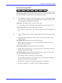
Example:
The following codes demonstrate the use of base buffer attributes ($B7 is the DBC
code for X, $B8 is Y, $C8 is an Intensified attribute, and $C0 is a Normal attribute):
$B7 $B7 $B7 $C8 $B8 $B8 $B8 $C0 $B7 $B7 $B7
Resulting printout:
XXXYYYXXX
(formatted mode)
or
XXX YYY XXX (unformatted mode)
DSC/DSE Extended Attributes
When the EAB feature is enabled, all base buffer characters and attributes have a corresponding attribute designation in the Extended Attribute Buffer (EAB).
If the EAB modifies a character byte in the base buffer, it is a character attribute (CA).
If the EAB modifies a field attribute in the base buffer, it is an extended field attribute
(EFA).
The format of the character attribute (CA) is:
Bit
Description
7 - 6 00 - Revert to the EFA
01 - Blink Character (ignored)
10 - Reverse Video Character (ignored)
11 - Underline Character (including spaces and nulls)
5 - 3 Ignored
2 - 0 000 - Revert to the EFA
001 - APL Character Set
The format of the extended field attribute (EFA) is:
Bit
Description
7 - 6 00 - Normal Mode
01 - Blink Character (ignored)
10 - Reverse Video Character (ignored)
11 - Underline Character (including spaces and nulls)
5 - 3 Ignored
2 - 0 000 - Base Character Set
001 - APL Character Set
Axis AX-7 Cobra+ Technical Reference
18
IBM 3270 CONTROL CODES
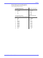
DSC/DSE Control Codes
The following control codes are valid in DSC/DSE mode:
Note:
Code Value Description
Page
NUL
EM
FF
NL
CR
19
19
19
20
20
00
01
02
03
05
Null
End of Message
Form Feed
New Line
Carriage return
1. These codes have different meanings in print and non-print fields in both formatted
and unformatted modes, as explained below.
Null (NUL)
$00
A NUL causes no action in formatted mode. The table below shows how NUL is
treated for different fields and modes:
Formatted mode Unformatted mode
Print field
NUL (see note)
Non-print field NUL (see note)
Note:
Space
Space
If True Screen Image (parameter #006) is set to ‘Yes’, NUL is treated as space in local
copy mode.
End of Message (EM)
$01
EM stops printing, and the remainder of the print buffer is ignored in a unformatted
print field. The table below shows how EM is treated for different fields and modes:
Formatted mode Unformatted mode
Print field
Space
Non-print field NUL
EM
Space
Form Feed (FF)
$02
FF moves the print position to the Top of Form position on the next page in formatted
and unformatted print and non-print fields:
Formatted mode Unformatted mode
Print field
FF
Non-print field FF
Axis AX-7 Cobra+ Technical Reference
FF
FF
19
IBM 3270 CONTROL CODES
New Line (NL)
$03
NL moves the print position to the left margin of the next line in an unformatted print
field. The table below shows how NL is treated for different fields and modes:
Formatted mode Unformatted mode
Print field
Space
Non-print field NUL
NL
Space
Carriage Return (CR)
$05
CR moves the print position to the left margin of the current line in an unformatted
print field. The table below shows how CR is treated for different fields and modes:
Print field
Non-print field
Axis AX-7 Cobra+ Technical Reference
Formatted mode
Unformatted mode
Space
NUL
CR
Space
20
IBM 3270 CONTROL CODES
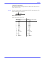
LU-1 (SCS) Control Codes
The following control codes are valid in LU-1 (SCS) mode:
Code Value
Description
Page
VCS
HT
GE
VT
FF
CR
ENP
NL
BS
IRS
INP
LF
ESC
SA
BEL
TRN
SHF
SVF
SLD
STO
SPD
PPM
Vertical Channel Select
Horizontal Tab
Graphic Escape
Vertical Tab
Form Feed
Carriage Return
Enable Presentation
New Line
Back Space
Interchange Record Separator
Inhibit Presentation
Line Feed
Escape
Set Attribute
Bell
Transparent
Set Horizontal Format
Set Vertical Format
Set Line Density
Set Text Orientation
Set Print Density
Print Presentation Media
21
22
22
22
22
20
22
23
23
23
23
23
23
23
24
24
25
26
27
27
27
28
04…
05
08
0B
0C
0D
14
15
16
1E
24
25
27
28…
2F
35…
2BC1…
2BC2…
2BC6…
2BD1…
2BD2NN29…
2BD2NN48…
Vertical Channel Select (VCS)
$04
VS
VCS moves the print position to a vertical tab position specified by the Set Vertical
Format (SVF) command. Vertical channels are defined by the Top Margin and the first
11 vertical tab stops.
The byte ‘VS’ selects the vertical channel. Valid values are:
Value Description
$81
$82
$83
$84
$85
$86
$87
$88
$89
$7A
$7B
$7C
Notes:
Vertical Channel 1
Vertical Channel 2
Vertical Channel 3
Vertical Channel 4
Vertical Channel 5
Vertical Channel 6
Vertical Channel 7
Vertical Channel 8
Vertical Channel 9
Vertical Channel 10
Vertical Channel 11
Vertical Channel 12
1. Vertical channels are supported when IBM Printer Emulation (parameter #045) is
set to ‘62’, ‘68’, or ‘24’. When set to ‘87’ or ‘14’, the VCS command is treated as a
Line Feed (LF).
2. Channel 1 is always set to the TM value.
Axis AX-7 Cobra+ Technical Reference
21
IBM 3270 CONTROL CODES
3. If no tab position is set for the selected channel number, the VCS command is
treated as a Line Feed (LF).
4. If the selected channel specifies a line number less than or equal to the current line,
the print position moves to the specified line on the next page.
Horizontal Tab (HT)
$05
HT moves the print position to the next higher tab stop specified by the Set Horizontal
Format (SHF).
Notes:
1. If the current print position is greater than or equal to the highest tab stop, HT is
treated as a space.
2. HT at MPP+1 moves the print position to Left Margin (LM) + 1 of the next line.
Graphic Escape (GE)
$08
GE indicates that the next byte represents an APL character.
Vertical Tab (VT)
$0B
VT moves the print position to the line specified by the next higher vertical tab stop.
Notes:
1. VT does not change the horizontal print position.
2. If the current line number is greater than or equal to the highest tab stop (or if no
tab stops are set), VT is treated as a Line Feed (LF).
Form Feed (FF)
$0C
FF moves the print position to the next Top of Form.
Carriage Return (CR)
$0D
CR moves the print position to Left Margin. If the current print position equals the Left
Margin, CR is ignored.
Enable Presentation (ENP)
$14
ENP has no effect on print operation.
Axis AX-7 Cobra+ Technical Reference
22
IBM 3270 CONTROL CODES
New Line (NL)
$15
NL causes a Carriage Return (CR) and a Line Feed (LF).
Back Space (BS)
$16
BS moves the print position one column to the left (even if the current print position is
equal to or less than Left Margin). BS in column 1 is ignored.
Interchange Record Separator (IRS)
$1E
IRS performs the same function as Line Feed (LF).
Inhibit Presentation (INP)
$24
INP has no effect on print operation.
Line Feed (LF)
$25
LF moves the print position to the next line without changing the horizontal print position.
Escape (ESC)
$27
Translates to ASCII $1B if parameter #40 (Extended Emulation Mode) =1 and parameter #41 (Escape Character) = 0.
Set Attribute (SA)
$28
TT
VV
SA specifies an attribute for all subsequent data. Each attribute is defined by two bytes
following the SA control code. An attribute remains valid until changed by a new SA
code, or a new SNA chain begins.
TT specifies the type of attribute. Valid values are:
Value Description
$00
$41
$42
$43
Reset
Highlight
Color
Character Set
Reset (TT = $00): All attributes are reset to normal. Byte VV must be ‘$00’.
Axis AX-7 Cobra+ Technical Reference
23
IBM 3270 CONTROL CODES
Highlight (TT = $41): Byte VV selects the type of highlight attribute. Valid values
are:
Value Description
$00
$F1
$F2
$F4
Normal
Blink (ignored)
Reverse image (ignored)
Underline
Color (TT = $42): Byte VV selects a color for subsequent printing. Valid values are:
Value Description
$00
$F1
$F2
$F3
$F4
$F5
$F6
$F7
Black
Blue
Red
Magenta
Green
Cyan
Yellow
Black
Character Set (TT = $43): Byte VV selects normal or APL character set. Valid values
are:
Value Description
$00
$F1
Normal character set
APL character set
Bell (BEL)
$2F
BEL causes the protocol converter to send the Bell Sequence (parameter #120) to the
printer.
Note:
1. By default, the Bell Sequence only results in a short beep, and the printer remains
on-line. An IBM printer would go off-line, and the alarm would sound
continuously.
Transparent (TRN)
$35
NN
D1...Dn
$36
NN
D1...Dn
TRN indicates the start of a transparent (pass-through) data stream. The count byte
(NN) defines the number of data bytes to follow (excluding the count byte). Valid NN
values are $01 - $FF.
Notes:
1. Character codes in the range $00 - $3F are printed as hyphens ( - ), i.e. control
codes in the transparent data stream will not be recognized.
2. The protocol converter supports an extension of the TRN command, where the
transparent data is interpreted as ASCII character codes. See parameter #042
(Option Select 1, bit 6: Extended SCS Transparency).
Axis AX-7 Cobra+ Technical Reference
24
IBM 3270 CONTROL CODES
Set Horizontal Format (SHF)
$2B
$C1
NN
MPP
LM
RM
T1...Tn
SHF sets the horizontal format control parameters: Maximum Print Position (MPP),
Left Margin (Left Margin), Right Margin (RM), and up to 128 horizontal tab stops
(T1...Tn). The count byte (NN) defines the number of bytes to follow (including the
count byte).
Note:
1. SHF should be followed by a New Line or Carriage Return to initialize the
horizontal format control parameters.
Count (NN): Valid range for the count byte is $01 - $83.
• A count of $01 sets all horizontal format control parameters to their default values.
Maximum Print Position (MPP): Defines the number of characters per line.
• If MPP is $00 (or not specified, i.e. the count byte NN is $01), the Maximum Print
Position is set to the default value, see note 1.
Notes:
1. The default MPP depends on the selected IBM Printer Emulation: IBM 3268 and
IBM 4224 use the parameter #004 (Maximum Print Position) value, IBM 3287,
IBM 3262 and IBM 4214 use the fixed value 132.
2. The MPP setting can be prevented by setting parameter #066, bit 3 (Option Select
2, Lock MPP) to 1.
Left Margin (LM): Defines the left-most print position. LM is the new print position
after New Line, Carriage Return, or Form Feed.
• If LM is greater than $00 and less than or equal to MPP, then Left Margin is set to
the LM value.
• If LM is $00, or not present (i.e. the count byte NN is less than $03), Left Margin is
set to column 1.
• LM is stored as the first horizontal tab stop.
Right Margin (RM): The Right Margin is not used, and the RM value is ignored.
Horizontal Tab Stops (T1...Tn): Defines the horizontal tab stops used by the Horizontal Tab (HT) control code.
• Valid tab stop columns are in the range from LM to MPP.
• If no tab stops are specified (i.e. the count byte NN is less than 5), the default is a
tab stop at each column between LM and MPP.
• Tab stops may be defined in any order.
Axis AX-7 Cobra+ Technical Reference
25
IBM 3270 CONTROL CODES
Set Vertical Format (SVF)
$2B
$C2
NN
FL
TM
BM
T1...Tn
SVF sets the vertical format control parameters: Form Length (FL), Top Margin (TM),
Bottom Margin (BM), and up to 128 vertical tab stops (T1...Tn). The count byte (NN)
specifies the number of bytes to follow (including the count byte).
Note:
1. SVF should be sent only in Top of Form position (i.e. after a Form Feed and before
any control code or character that would change the current print position). SVF in
any other position will generate a Form Feed.
Count (NN): Valid range for the count byte is $01 - $83.
• A count of $01 sets all vertical format control parameters to their default values.
Form Length (FL): Defines the number of lines per page.
• If FL is $00 (or not specified, i.e. the count byte NN is $01), the Form Length is set
to 1.
Note:
1. The FL setting can be prevented by setting parameter #099 (Lock Form Length) to
‘Yes’.
2. If parameter #44 (Option Select 1) bit 5 ($20) is set, then Form Length is set to
parameter #001.
Top Margin (TM): Defines the first print line on the page.
• If TM is $00 (or not specified, i.e. the count byte NN is less than $03), the Top
Margin defaults to print line 1.
Bottom Margin (BM): Defines the last print line on the page.
• If BM is $00 (or not specified, i.e. the count byte NN is less than $04), the Bottom
Margin is equal to Form Length.
Vertical Tab Stops (T1...Tn): Defines the vertical tab stops used by the Vertical Tab
(VT) and Vertical Channel Select (VCS) functions.
• Valid tab stop values are in the range from TM to BM.
• If no tab stops are specified (i.e. the count byte NN is less than $05), the default is a
tab stop at each line between TM and BM.
• The TM value is stored as the first tab stop and the Vertical Channel 1.
• Tab stops T1 through T11 are used for Vertical Channels 2 through 12.
Axis AX-7 Cobra+ Technical Reference
26
IBM 3270 CONTROL CODES
Set Line Density (SLD)
$2B
$C6
NN
LD
SLD sets the number of lines per inch (LPI). The count byte NN specifies the number
of bytes to follow (including the count byte).
Count (NN): Valid values are:
Value Description
$01
$02
LPI is determined by parameter #002 (Line Density)
LPI is determined by the byte LD value
Line Density (LD): Valid values are:
Value Description
$00
$18
$12
$0C
$09
Note:
6 Lines per Inch
3 Lines per Inch
4 Lines per Inch
6 Lines per Inch
8 Lines per Inch
1. Line Density setting can be prevented by setting parameter #111 (Lock LPI) to
‘Yes’.
Set Text Orientation (STO)
$2B
$D1
$06
$83
XX
$00
$2D
$00
STO sets the print direction.
Print Direction (XX): Valid values are:
Value Description
$00
$5A
Note:
Left-to-Right direction
Right-to-Left direction
1. STO is only used by Arabic and Hebrew languages.
Set Print Density (SPD)
$2B
$D2
NN
$29
$00
VV
SPD sets the number of characters per inch (CPI). The count byte NN specifies the
number of bytes to follow (including the count byte).
Notes:
1. The SPD becomes effective immediately after it is received. Data following for the
same print line will be printed with the new CPI setting,
2. A CPI change affects the current print position, the left margin (LM), the maximum
print position (MPP), and the horizontal tab (HT) stop positions.
3. If CPI changes within a print line, a CR and spaces will sent to the printer to
maintain the current print position.
4. The CPI setting can be prevented by setting parameter #110 (Lock CPI) to ‘Yes’.
Axis AX-7 Cobra+ Technical Reference
27
IBM 3270 CONTROL CODES
Count (NN): Valid values are:
Value Description
$02
$04
CPI is determined by parameter #004 (Character Density)
CPI is determined by the byte VV value
Character Density (VV): Valid values are:
Value Description
$00
$05
$0A
$0C
$0F
$10
Note:
10 Characters per Inch
5 Characters per Inch
10 Characters per Inch
12 Characters per Inch
15 Characters per Inch
17.1 Characters per Inch
1. 5 CPI is a non-IBM LU-1 (SCS) value.
Print Presentation Media (PPM)
$2B
$D2
NN
$48
$00 $00
FC
SD
$00 $00
PQ
$00 $00 $00
PPM selects a source drawer and also sets the print quality. The count byte NN specifies the number of bytes to follow (including the count byte).
Count (NN): Valid range is $02 through $0C.
Forms Mode (FC): Valid values are:
Value Description
$00
$01
$02
No change from current selection
Paper
Envelope (Envelope Feeder)
Source Drawer (SD): Valid values are:
Value
Description
$00
$01
$02
$03 - $FF
No change from current selection
Select primary cassette (Sheet Feeder 1)
Select secondary cassette (Sheet Feeder 2)
No change from current selection
Print Quality (PQ): Valid values are:
Value Description
$00
$01
$02
No change from current selection
Data Processing Quality (Draft)
Near Letter Quality (NLQ)
Axis AX-7 Cobra+ Technical Reference
28
THEORY OF OPERATION
SECTION 3
THEORY OF OPERATION
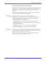
The protocol converter receives IBM LU-1 (SCS) and DSC/DSE Character Codes and
Control Codes, and translates them into ASCII Character Codes and Control
Commands which are sent to an attached printer.
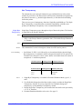
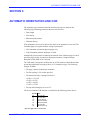
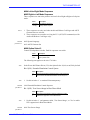
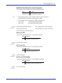
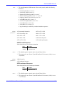
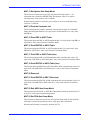
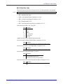
Data Flow Chart
The basic data flow is shown in the following diagram:
PC/LAN
Serial
PC/LAN
Parallel
Data is temporarily stored in the Communications Buffer (note that the
communications buffer also holds printer information data directed to the host, see the
previous section).
As soon as a buffer of data is received, the protocol converter starts processing the
data. The data takes different paths depending on the current mode, LU-1 (SCS), or
DSC/DSE.
Axis AX-7 Cobra+ Technical Reference
29
THEORY OF OPERATION
LU-1 (SCS) Data
Processing
The data is separated into LU-1 (SCS) Control Codes ($00 - $3F), and Character Codes
($40 - $FF).
The Control Codes are passed through the LU-1 (SCS) Emulation, which translates
them into ASCII Control Commands.
The Character Codes are translated into Device Buffer Code (DBC) using the EBCDIC
to DBC translation table for further processing. DBC is the protocol converter internal
character representation format, common to all print modes.
DSC/DSE Data
Processing
The data is separated into DSC/DSE Control Codes ($00 - $07), Character Codes ($08
- $BF), and Base Buffer Attributes ($C0 - $FF).
Control Codes and Base Buffer Attributes are passed through the DSC/DSE
Emulation, which translates them into ASCII Control Commands.
The Character Codes are translated into ASCII character codes using the DBC to
ASCII translation table.
Extended
Emulation
Output Driver
This module processes all non-IBM functions referenced in the data stream, such as
Hex Transparency and Configuration Commands. These functions are explained later
in this manual.
This module transfers the ASCII Character Codes and Control Commands to an
attached printer using either the parallel (Centronics), *or serial (RS-232) interface.
The interface type is automatically determined by the type of printer cable installed.
The Output Driver module also controls the PC-Host Sharing feature, described later in
this manual.*
* Does not apply to the AXIS 370 Cobra.
Axis AX-7 Cobra+ Technical Reference
30
THEORY OF OPERATION
Protocol Converters Data Processing Control
The function of the modules described here depends heavily on the protocol converter
configuration. i.e. changing the IBM Printer Emulation, the ASCII Printer Driver, or
utilizing some of the protocol converter internal functions will affect the data
processing.
This is the reason why the protocol converter is so flexible; it may be configured to
match virtually any host application and ASCII printer.
The Parameter
List
The Parameter List is the complete set of parameters making up the
protocol converter configuration. There are several different types of parameters:
• IBM System Parameters: e.g. IBM Printer Emulation, System Language,
Intervention Time, and Character Buffer Size.
• Front panel switches: e.g. Form Length, Line Density, and Left Margin.
• Internal function controls: e.g. Extended Emulation Mode, Bar Code Driver, and
PC-Host Sharing Time-out.
• ASCII Printer controls: e.g. True Form Feed and ASCII Character Set.
• ASCII Control Commands: e.g. LPI, CPI and Underline Sequences.
Printer Drivers
A Printer Driver is mainly a subset of the Parameter List, containing all parameters of
the groups ASCII Printer Controls and ASCII Control Commands, plus some of the
Front Panel Switches and Internal Function Controls.
This means that selecting a driver matching your printer will preset all relevant
parameters, so that no further configuration is necessary.
Axis AX-7 Cobra+ Technical Reference
31
EXTENDED EMULATION MODE
SECTION 4
EXTENDED EMULATION MODE
During normal mode of operation the protocol converter, together with your printer,
emulates the IBM printer selected in your configuration. In addition, the Extended
Emulation Mode gives you access to functions not available in standard IBM printers.
These functions are:
• Hex Transparency
• Configuration From the System
• Advanced Printer Control
• Modification of the Character Translation Tables
• User Definable Strings
• String Substitutions
• Bar Code printing
The following parameters control the Extended Emulation Mode:
#040 Extended Emulation Mode
#041 Escape Character
#070 Transparency Lead-in Sequence
#071 Configuration Lead-in Sequence
#072 Transparency/Configuration Trailer Sequence
#104 Extended Emulation Control Sequence
The parameters are described on page 64. There are also a number of internal functions
in the Extended Emulation Mode, page 106.
Axis AX-7 Cobra+ Technical Reference
32
EXTENDED EMULATION MODE
Using Extended Emulation Mode
To use the Extended Emulation Mode functions, the Extended Emulation Mode has to
be activated. This is done by inserting the enter Extended Emulation Mode sequence in
your document. Any number of extended emulation functions can then be used before
Extended Emulation Mode is deactivated using the exit Extended Emulation Mode
sequence.
Example:
Note:
&&??%%P
%P
=128,1
=207,10
%
%0C
(enter Extended Emulation Mode) Note 1
(Configuration Lead-In sequence, page 37)
(program parameter #128. page 37)
(internal function call. page 37)
(Transp./Config. Trailer Sequence, page 37)
(Single byte transparency (page 39) or User
Defined string. (page 49))
%%1B”&a8L”% (Multi-byte transparency. page 40)
&&??000
(exit Extended Emulation Mode) Note 2
1. This is the default enter Extended Emulation Mode sequence. The sequence can be
altered if needed. See also page 34.
2. This is the default exit Extended Emulation Mode sequence. The sequence can be
altered if needed. See also page 35.
Axis AX-7 Cobra+ Technical Reference
33
EXTENDED EMULATION MODE
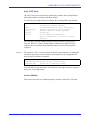
Enter Extended
Emulation Mode
Syntax:
The Extended Emulation Mode is entered by inserting the enter Extended Emulation
Mode sequence into your document.
<EECS><a><b><c>
• <EECS> is the Extended Emulation Control Sequence (Parameter #104). The
default sequence is ‘&&??’.
• <a>, <b> and <c> are three printable characters to be used for subsequent extended
emulation functions.
Result:
Note:
Example:
Number Title
New contents
#040
#041
#070
#071
#072
2
<a>
<a><b>
<a><c>
<a>
Extended Emulation Mode
Escape Character
Transparency Lead-in Sequence
Configuration Lead-in Sequence
TRN/Conf. Trailer Sequence
1. The characters <a>, <b> and <c> must be different from the characters in the
<EECS> sequence.
The example below shows how Extended Emulation Mode can be entered using the
default EECS (‘&&??’).
&&??%%P
Result:
Number Title
New contents
#040
#041
#070
#071
#072
2
$2E
$2E $2E
$2E $AF
$2E
Axis AX-7 Cobra+ Technical Reference
Extended Emulation Mode
Escape Character
Transparency Lead-in Sequence
Configuration Lead-in Sequence
TRN/Conf. Trailer Sequence
(%)
(%%)
(%P)
(%)
34
EXTENDED EMULATION MODE
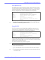
Exit Extended
Emulation Mode
Syntax
To exit the Extended Emulation Mode and to resume normal emulation, the exit
Extended Emulation Mode sequence is used.
<EECS>000
• <EECS> is the Extended Emulation Control Sequence (Parameter #104). The
default sequence is ‘&&??’.
The example below shows how Extended Emulation Mode can be exited using the
default EECS (‘&&??’).
Example:
&&??000
Result:
Number Title
New contents
#040
#041
#070
#071
#072
0
$00
<empty>
<empty>
<empty>
Axis AX-7 Cobra+ Technical Reference
Extended Emulation Mode
Escape Character
Transparency Lead-in Sequence
Configuration Lead-in Sequence
TRN/Conf. Trailer Sequence
35
EXTENDED EMULATION MODE
Extended Emulation Mode Types
There are six different Emulation Mode types. This subsection briefly describes the
main features of each type. More details will be given for each extended emulation
function.
Type 0 (No
Extended
Emulation Mode)
This is the default mode. No extended emulation functions are active. The Escape
character and the transparency and configuration lead-in sequences are printed as
normal characters when received.
If the Extended Emulation Control Sequence is received, mode type 2 is entered.
Type 1 (Escape
Character
translates to $1B
ASCII)
The Escape character is translated to the ASCII escape ($1B). The transparency and
configuration lead-in sequences are printed as normal characters when received.
If the Extended Emulation Control Sequence is received, mode type 2 is entered.
Type 2 (The
default Extended
Emulation Mode)
This mode is entered when the Extended Emulation Control Sequence is received. The
Escape character and the transparency and configuration lead-in sequences will start
extended emulation functions, and will not be printed. See the respective extended
emulation functions for details.
Type 3 (MPI
transparency
compatible mode)
This mode is used when replacing an existing MPI protocol converter, see page 145 for
details.
Type 4 (Memorex
2068
transparency
compatible mode)
This mode is used when replacing an existing Memorex Telex 2068 printer, see page
144 for details.
Type 5 (Maersk
Data
transparency
compatible mode)
This mode is used with the Maersk Data MD-GRAFTEXT software, see page 146 for
details.
Axis AX-7 Cobra+ Technical Reference
36
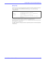
EXTENDED EMULATION MODE
Configuration from the System
This function enables you to configure the protocol converter without using the
Configuration from a Terminal (described in the User’s Manual). The configuration is
done by including parameter programming commands and internal function calls in
your document. To use these commands the Extended Emulation Mode has to be
invoked, page 33.
Syntax:
<CLI>=<Parameter/Funct.1>[=<Parameter/Funct.2>...=<Parameter/Funct.n>]<TCT>
• <CLI>is the configuration Lead-In sequence (parameter #071). The default
sequence is ‘%P’.
• <Parameter/Funct.n> are parameter programming commands or internal function
calls.
• <TCT> is the Transparency/Configuration Trailer Sequence (parameter #072). The
default sequence is ‘%’.
Parameter
Programming
Syntax:
The parameter programming command consists of an equal sign, a parameter number,
a comma, and a parameter value. The command is valid only within a configuration
sequence.
=<Parameter Number>,<Parameter Value or String>
Any number of parameters can be programmed before the TCT stop sequence.
Note:
Internal Function
Calls
Syntax:
1. Only decimal parameter numbers may be used.
The internal function call consists of an equal sign, a function number, a comma, and a
function parameter value. The command is valid only within a configuration sequence.
The internal functions are described in Section 10, page 106:
=<Function Number>,<Argument (not all functions)>
Any number of functions can be called before the TCT stop sequence.
Axis AX-7 Cobra+ Technical Reference
37
EXTENDED EMULATION MODE
Data
Representation
and Delimiters
during
Configuration
Parameter and function numbers must always be specified as decimal values. Other
data can use alternative representations but must, during Configuration from the
System, be separated by a delimiter.
Data Type/Delimiter
Character
Note 1
Example Of Use
Parameter Number
= ($11)
# ($2C)
§ ($2B)
Note 2
$ ($1A)
=120
#120
§120
12
$0C or $0c Note 3
Decimal Value
Hexadecimal Value
¤
*
'
"
Text String (EBCDIC char) /
%
‘Yes’ Value
y
Y
‘No’ Value
n
N
Comment (start)
(
Comment (stop)
)
Delimiter
SP
,
.
:
;
Binary Value
Text String (ASCII char)
Notes:
($1F)
($BF)
($12)
($13)
($14)
($2E)
($98)
($B8)
($8D)
($AD)
($0D)
($0C)
($10)
($33)
($32)
($34)
($BE)
¤0C or ¤0c
*00100111
'ASCII CODED TEXT'
"ASCII CODED TEXT"
/DBC CODED TEXT/
%DBC CODED TEXT%
y
Y
n
N
(comments will be ignored)
(comments will be ignored)
=120 "DATA" Note 4
=120,"DATA"
=120."DATA"
=120:"DATA"
=120;"DATA"
1. Character codes are the DBC codes that are valid. If you use SCS (LU-1) make
sure that a System Language matching your host settings is used.
2. No character should be used to denote a decimal value.
3. When programming string parameters ‘$’ or ‘¤’ is only needed before the first
hexadecimal value, e.g. $31,$32,$33,$34 is equivalent to $31323334.
4. Only valid if set in parameter #100 (option select 3).
5. Characters used in the parameters that control Extended Emulation Mode (see page
33) cannot be used as delimiters or data representation.
Axis AX-7 Cobra+ Technical Reference
38
EXTENDED EMULATION MODE
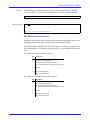
Hex Transparency
The transparency (pass through) function lets you send data directly to the printer
without any conversion. The data could be ASCII printer commands not supported by
the protocol converter (e.g. double height characters), or font data for downloading
fonts to the printer.
There are two types of transparency functions: Single Byte and Multibyte. The Single
Byte Transparency is included mainly to maintain compatibility with older Axis
products, the Multibyte Transparency is the recommended method.
Single Byte
Transparency
Syntax:
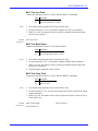
Single-Byte Transparency passes through one byte of data to the printer. The function
is controlled by the Escape Character.
<ESC><Hexadecimal Value (two digits)>
• <ESC> is the Escape Character, (parameter #041). The default Escape Character is
‘%’.Example:
Syntax:
Result:
Error handling:
%1B&a8L
This command will set the left margin to column 8 on HP LaserJet printers.
• Invalid data: If <ESC> isn’t followed by two hexadecimal digits, then the Single
Byte transparency is terminated, and the subsequent characters will be printed. The
first table below shows the correct syntax, and the second table shows the results of
a misplaced ‘x’ in different positions:
Intended sequence Resulting printout Character codes sent
%41
A
$41
Entered sequence Resulting printout Character codes sent
%x41
%4x1
%41x
Notes:
x41
x1
Ax
$78 $34 $31
$04 $78 $31
$41 $78
1. Single Byte Transparency is available in Extended Emulation Mode, types 2, 3,
and 5.
2. User Definable Strings (described later in this section) overrides the Single Byte
Transparency function. If you are using both User Definable Strings and
transparency, use the Multibyte Transparency instead.
3. During Single-Byte Transparency, the hexadecimal value shall not be preceded by
a ‘$’ or ‘¤’ character.
4. Extended Emulation Mode has to be active. See page 33.
Axis AX-7 Cobra+ Technical Reference
39
EXTENDED EMULATION MODE
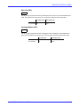
Multibyte
Transparency
Syntax:
Multi-Byte Transparency passes through any number of bytes to the printer. Once
Extended Emulation Mode has been entered (see page 33), the function is controlled by
the Transparency Lead-In Sequence and the Transparency/Configuration Trailer
Sequence.
<TLI><Hexadecimal Value1>[<Hexadecimal Value2>...
<Hexadecimal Valuen>]<TCT>
or
Syntax:
<TLI>"<sequence of ASCII characters>"<TCT>
• <TLI> is the Transparency Lead-In Sequence (parameter #070). The default
sequence is ‘%%’
• <TCT> is the Transparency/Configuration Trailer Sequence (parameter #072). The
default sequence is ‘%’
Any number of hexadecimal values and sequences of ASCII characters can be sent to
the printer before the <TCT> stop sequence.
Example:
The three sequences below perform the function, sending the command ‘EC& a 8 L’ to
the printer. (This is the HP LaserJet command to set the left margin to the 8th column).
%%1B2661384C%
or
%%1B"&a8L"%
or
%%1B%&a8L
Axis AX-7 Cobra+ Technical Reference
40
EXTENDED EMULATION MODE
The first sequence shows the hexadecimal format, where the ASCII character codes are
given by their hexadecimal representation.
The second sequence shows a mixed hexadecimal and literal format, giving an
improved readability.
In the third sequence, the printable characters are entered as normal text. This is
generally not recommended, since a buffer break may disrupt the command by
generating control codes.
Error handling:
• Invalid data: If the lead-in sequence isn’t followed by hexadecimal digits, then the
Multibyte transparency is terminated, and the subsequent characters will be printed.
The first table below shows the correct syntax, and the second table shows the
results of a misplaced ‘x’ in different positions:
Intended sequence Resulting printout Character codes sent
%%41%42
A42
$41 $34 $32
Entered sequence Resulting printout Character codes sent
%%x41%42
%%4x1%42
%%41x%42
Notes:
x41B
x1B
AxB
$78 $34 $31 $42
$04 $78 $31 $42
$41 $78 $42
1. Multibyte Transparency is available in Extended Emulation Mode, types 2, 3, and
5.
2. During Multi-Byte Transparency, the hexadecimal values shall not be preceded by
a ‘$’ or ‘¤’ character.
3. Extended Emulation Mode has to be active. See page 33.
Axis AX-7 Cobra+ Technical Reference
41
EXTENDED EMULATION MODE
Sending Control
Commands to the
printer
Syntax:
The Multi Byte Transparency function can also be used for sending any control
command sequences stored in the parameter list to the printer by referring to their
parameter numbers. This function provides a versatile method of printer control,
independent of the selected printer driver.
<TLI>=<Parameter Nr.1>[=<Parameter Nr.2>...
=<Parameter Nr.n>]<TCT>
• <TLI> is the Transparency Lead-In Sequence (parameter #070). The default
sequence is ‘%%’
• <TCT> is the Transparency/Configuration Trailer Sequence (parameter #072). The
default sequence is ‘%’
Example:
Syntax:
Error handling:
Notes:
The line below results in the Set Bold Face and Set Italic sequences being sent, the text
‘Example:’ is printed just as the title above, and the Exit Bold face and Exit Italic
sequences are sent.
%%=56=114%Example:%%=57=115%
• Invalid parameter number: Undefined and non-sequence parameters are ignored.
1. Extended Emulation Mode has to be active. See page 33.
2. Only decimal parameter numbers may be used.
Axis AX-7 Cobra+ Technical Reference
42
EXTENDED EMULATION MODE
Data
Representation
and Delimiters
during Multi-Byte
Transparency
Parameter numbers must always be specified as decimal values. Pass through data can
be specified as either hexadecimal values or as ASCII data. Delimiters can be used
during Multi-Byte Transparency but are not mandatory.
Data representation and delimiters during Multi-Byte Transparency:
Data Type/Delimiter
Parameter Number
Character Example Of Use
Note 1
= ($11)
# ($2C)
§ ($2B)
Hexadecimal Value
Note 2
Text String (ASCII char)
'
($12)
"
($13)
Delimiter
SP ($10)
, ($33)
.
($32)
: ($34)
;
($BE)
Suppress text & control codes + ($31)
Normal mode
- ($35)
Notes:
=120
#120
§120
0C or 0c
'ASCII CODED TEXT'
"ASCII CODED TEXT"
=120 "DATA"
Note 3
=120,"DATA"
=120."DATA"
=120:"DATA"
=120;"DATA"
+
Note 4
Note 4
1. Character codes are the DBC codes that are valid. If you use SCS (LU-1) make
sure that a System Language matching your host settings is used.
2. No character should be used to denote a hexadecimal value.
3. Only valid if set in parameter #100 (option select 3).
4. See page 145.
Axis AX-7 Cobra+ Technical Reference
43
EXTENDED EMULATION MODE
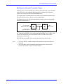
Redefinition of Lead-in and Trailer Sequences
It is sometimes desirable to change the Transparency Lead-in and Trailer Sequences,
e.g. when as existing application uses non-standard sequences. This is done either
using a Configuration File, or using the Configuration from a Terminal.
Using a
Configuration
File
A configuration file is a document containing parameter programming commands and
internal function calls (see page 37), setting up the protocol converter for different
applications or printers.
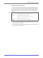
Example:
An application uses the sequences ‘!?<’ and ‘>&’ to start and stop hex transparency.
The protocol converter can be set up for this application by the following configuration
file:
&&??%%P
%P
=40,2
=70,/!?</
=72,/>&/
=207,10
=207,12
>&
Notes:
Using
Configuration
from a Terminal
(Enter Extended Emulation Mode)
(Configuration Lead-in Sequence)
(Set Ext. Emulation Type 2 permanently)
(Redefine Transparency Lead-in Sequence)
(Redefine TRN/Conf. Trailer Sequence)
(Initialize)
(Save configuration permanently)
(End of configuration - note the new sequence)
1. The command ‘=40,2’ is necessary since the Enter Extended Emulation command
sets Type 2 only temporarily. If omitted, the Extended Emulation Mode will be ‘0’
after the next Power up.
2. The Lead-in and Trailer sequences must be entered as DBC characters, hence the
‘/’ quotation marks.
The same configuration as in the previous example can also be obtained using the
Configuration from a Terminal utility:
1. Start the Configuration from a Terminal as described in the User’s Manual.
2. Select the ‘Edit Parameters’ entry in the Main Menu.
3. Move down to parameter #40 (Extended Emulation Mode), and press Right to enter
edit mode. Change the value to ‘2’, then press Enter.
4. Move down to parameter #70 (Transparency Lead-in Sequence). Change this
sequence to ‘$19, $18, $09’, the DBC character codes for ‘!?<’.
5. Change parameter #72 (Transparency/Configuration Trailer Sequence) to ‘$08,
$30’, the DBC character codes for ‘>&’.
6. Press Enter to leave the parameter editor. When back to the Main Menu, select
‘Save’, and then ‘Exit’.
The configuration is now completed.
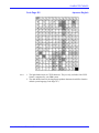
Axis AX-7 Cobra+ Technical Reference
44
EXTENDED EMULATION MODE
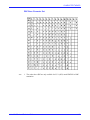
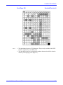
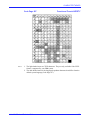
Modifying the Character Translation Tables
Normally, there is no need to modify the character translation tables, since the tables
activated by the System Language and Printer Driver selections are designed to
produce the same printouts as the emulated IBM printer.
If you should need to print characters not available in the standard translation tables,
this section describes how to do the necessary modifications.
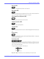
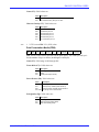
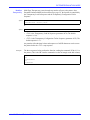
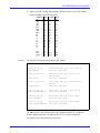
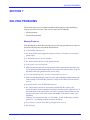
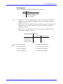
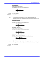
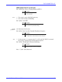
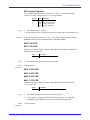
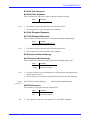
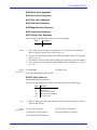
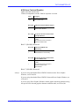
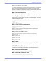
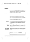
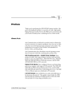
The diagram below is an excerpt from the data flow chart on page 29, showing the
character translation process:
LU-1 (SCS) data
(EBCDIC Char. Codes)
EBCDIC
to
DBC
DBC
Char. Codes
DBC
to
ASCII
ASCII
Char. Codes
DSC/DSE data
(DBC Char. Codes)
LU-1 data stream EBCDIC codes are first translated into DBC (Device Buffer Code),
which is the internal character representation format. The DBC codes are then
translated into ASCII codes.
DSC/DSE data stream DBC codes are translated directly into ASCII codes.
Notes:
1. The active EBCDIC to DBC translation table depends on the selected System
Language.
2. The active DBC to ASCII translation table depends on the selected ASCII
Character Set, which is a part of the Printer Driver.
Axis AX-7 Cobra+ Technical Reference
45
EXTENDED EMULATION MODE
The DBC to
ASCII
Translation Table
The DBC to ASCII table is modified by the internal function #205 (see page 107). All
table positions $00 trough $FF may be modified, but note that only positions $08
through $BF are used in DSC/DSE mode.
Each table position may contain either a single ASCII code, or a sequence of ASCII
codes. The length of these sequences are only limited by the Free String Area.
Example:
If the Printer Driver HP LaserJet III with the ASCII Character Set PC-850 is selected,
the following commands replaces the ‘~’ with a ‘♦’ in the DBC to ASCII table. This
will print the tilde character as a filled diamond in both LU-1 (SCS) and DSC/DSE
modes.
Since the filled diamond is not available in PC-850, it is necessary to temporarily
switch character sets:
%P
=205,$3B,$1B,$28,$36,$4D,$C1,$1B,$28,$31,$32,$55
=207,10
=207,12
%
• ‘=205’ is the Edit DBC to ASCII Table function call.
• ‘$3B’ is the table position for the tilde character.
• ‘$1B,$28,$36,$4D’ is the PCL 4 command ‘EC (6M’, which selects the Ventura
Math as primary symbol set.
• ‘$C1’ is the ASCII code for the filled diamond in the Ventura Math symbol set.
• ‘$1B,$28,$31,$32,$55’ is the PCL 4 command ‘EC (12U’, which selects the PC-850
as primary symbol set.
Note:
1. The ASCII codes $00, $03, $08, $0A, $0C, $0D, $0E, $1B, $20 and $5F have
special meanings to the output driver. If a DBC code is translated to any of these
codes, the ASCII code might be translated, buffered, or not sent to the printer at all.
To avoid this, translate these DBC codes to an ASCII sequence. ASCII sequences
are sent directly to the printer without any conversion by the output driver.
Example: To translate DBC code $BF to ASCII $03, use ‘=205,$BF,$00,$03’. ($00
is ignored by most printers)
2. Extended Emulation Mode has to be active. See page 33.
Axis AX-7 Cobra+ Technical Reference
46
EXTENDED EMULATION MODE
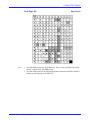
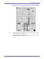
The EBCDIC to
DBC Translation
Table
Most translation table modification requirements are well taken care of by editing the
DBC to ASCII table. However, there are a few cases where the EBCDIC to DBC also
has to be modified:
• A System Language not supported by the protocol converter (e.g. Greek or Hebrew)
is used.
• Some characters should be translated differently in LU-1 and DSC/DSE modes.
The EBCDIC to DBC table is modified by the internal function #204 (see page 106).
The table positions available for editing are $40 through $FF. Each position contains
one DBC character code.
Example 1:
In this example, the ‘~’ prints as a‘♦’ in DSC/DSE mode (local copy), but still as a ‘~’
in LU-1 mode (system printouts):
%P
=204,$A1,$E5
=205,$E5,$7E
=205,$3B,$1B,$28,$36,$4D,$C1,$1B,$28,$31,$32,$55
=207,10
=207,12
%
• The first command remaps the EBCDIC tilde ($A1) to the previously unused DBC
position $E5.
• Next, the DBC position $E5 is defined as $7E, the PC-850 code for the tilde
character.
• Finally, the DBC position $3B is defined as the filled diamond, as in the previous
example.
Note:
1. Extended Emulation Mode has to be active. See page 33.
Axis AX-7 Cobra+ Technical Reference
47
EXTENDED EMULATION MODE
Example 2
This time the ‘~’ prints as a ‘~’ in DSC/DSE mode (local copy), and as a ‘♦’ in LU-1
mode (system printouts):
%P
=204,$A1,$E5
=205,$E5,$1B,$28,$36,$4D,$C1,$1B,$28,$31,$32,$55
=207,10
=207,12
%
• The EBCDIC tilde ($A1) is remapped to the DBC position $E5.
• $E5 is then defined as the filled diamond.
Notes:
How to create a
Custom System
Language
1. The DBC tilde does not have to be redefined in this case.
2. Extended Emulation Mode has to be active. See page 33.
Using the information given in the previous sections, you can create a new System
Language by following these steps:
1. Select the default System Language (US English), and the Printer Driver matching
your printer. If you are using an ASCII language different from a Printer Driver
default, you might need to modify the power-up sequence (parameter #060) to
select the correct ASCII language in your printer.
2. Make a printout of the DBC to ASCII table.
3. Modify the table positions required.
4. When the DBC to ASCII table is correct, print out the EBCDIC to ASCII and
EBCDIC to DBC (hex) tables.
5. Modify the EBCDIC to DBC table so that the EBCDIC to ASCII table prints
correctly.
This method applies both to Configuration from the System, and Configuration from a
Terminal. In the latter case, refer to the User’s Manual.
Axis AX-7 Cobra+ Technical Reference
48
EXTENDED EMULATION MODE
User Definable Strings
There are 255 User Definable String available, commonly used for advanced printer
control. The strings are programmed by internal function #209 (see page 111), and can
be activated in your applications by using the Escape Character followed by the string
number.
Application
Example Typeface Control
Configuration file::
The following example demonstrates how the User Definable Strings can be used for
HP LaserJet III typeface control:
%P
=209,$01,$28,$73,$33,$54
=209,$02,$28,$73,$30,$54
=209,$03,$28,$73,$34,$54
=209,$04,$28,$73,$35,$54
=209,$05,$28,$73,$37,$54
=207,10
=207,12
%
(Select
(Select
(Select
(Select
(Select
Courier typeface)
Line Printer typeface)
Helvetica typeface)
Times Roman typeface)
Script typeface)
This configuration file defines the User Definable Strings $01 through $05 as typeface
selection using the PCL4 ‘EC( s # T’ command, where ‘#’ is the typeface number.:
Example document:
%01
%02
%03
%04
%05
This
This
This
This
This
line
line
line
line
line
is
is
is
is
is
printed
printed
printed
printed
printed
with
with
with
with
with
the
the
the
the
the
Courier typeface
Line Printer typeface
Helvetica typeface
Times Roman typeface
Script typeface
A User Definable String is activated by the Escape Character followed by the string
number in hexadecimal format, without a leading dollar sign.
Resulting printout:
This line is printed with the Courier typeface
This line is printed with the LinePrinter typeface
This line is printed with the Helvetica typeface
This line is printed with the Times Roman typeface
This line is printed with the Script typeface
This is how the HP LaserJet III prints the document.
Note
1. Extended Emulation Mode has to be active. See page 33.
Axis AX-7 Cobra+ Technical Reference
49
EXTENDED EMULATION MODE
String Substitutions
The String Substitution function searches the output data stream for specified
sequences of ASCII characters (Match Strings), and substitutes them other sequences
(Substitute Strings).
This function is part of the Output Driver (see the flowchart on page 29), meaning that
all substitutions take place after the character and control code conversion.
The Match Strings and Substitute Strings are defined by the internal function #210, see
page 112.
Application
Example - Printer
Replacement
If your documents contain printer control commands, you will have to replace these
commands with new ones when the printer is replaced. Instead of changing the
documents, you can let the protocol converter substitute the commands prior to
printing.
The configuration file below makes the protocol converter substitute IBM Proprinter
commands for start and stop underlining with the corresponding HP LaserJet III
commands:
%P
=210,$01,$1B,$2D,$31
=210,$02,$1B,$26,$64,$44
=210,$03,$1B,$2D,$30
=210,$04,$1B,$26,$64,$40
=207,10
=207,12
%
Note:
(Start underline - IBM Proprinter)
(Start underline - HP LaserJet III)
(Stop underline - IBM Proprinter)
(Stop underline - HP LaserJet III)
1. Extended Emulation Mode has to be active. See page 33.
Axis AX-7 Cobra+ Technical Reference
50
EXTENDED EMULATION MODE
Bar Codes
The bar code function gives you access to a range of standard bar code types resident in
the protocol converter. Each bar code printout can be individually defined regarding
type, size, text below, and horizontal start position.
Bar codes are defined and printed by two internal functions:
• #211 Define Bar Code
• #212 Print Bar Code Data
These functions are described on page 113.
There are also two parameters controlling the bar code printouts:
• #093 Bar Code Driver: The graphics driver used for bar code printing.
• #094 Bar Code Attributes: Controls the appearance of the bar code printouts.
See page 90 for a description of these parameters.
The following bar code types are supported:
Type
Length (characters)
Valid characters
Check sum digit
1: Code 39
3: UPC-A
8: EAN8
9: EAN13
12: 2 of 5 Interleaved
13: Codabar Matrix
*17: Code 128
1 - 32
11
7
12
1 - 32
2 - 34 (incl. start/stop)
1-32
0 - 9,A - Z, Symbols
0-9
0-9
0-9
0-9
0 - 9, Symbols, A - D
Full 128 character
ASCII set, 4 Func
No
Yes
Yes
Yes
No
No
Yes
*Applies to the AX-7 Cobra+ and the AXIS 370 Cobra only.
Notes:
1. The symbols supported by Code 39 are plus (+), minus (-), period (.), slash (/),
percent (%), dollar ($), apostrophe (') and space(‘ ’). The space character must be
given in hex. Example: "Code", $20, "39".
2. The symbols supported by Codabar Matrix are plus (+), minus (-), period (.), slash
(/), dollar ($), and colon (:). A - D can only by used as start and stop characters.
3. Bar codes can only be printed vertically, and only one bar code per line. By using
page position commands on laser printers and reverse linefeeds on matrix printers
more than one barcode can be printed on the same line.
4. Normal text can be printed both before and after the bar code
5. The text below is always printed in 12 CPI, regardless of the CPI setting.
6. The protocol converter will lose track of the vertical print position when printing
bar codes. End bar code printouts with a Form Feed to maintain the page
formatting.
7. Extended Emulation Mode has to be active. See page 33.
8. Applies to Code 128 only. To get all characters correctly printed it is assumed that
Code Page 037 (English US) is used.
Axis AX-7 Cobra+ Technical Reference
51
EXTENDED EMULATION MODE
9. Applies to Code 128 only. Non printable characters must be entered in numeric
form, according to the following table:
Character ASCII Character ASCII
Example:
NUL
SOH
STX
ETX
EOT
ENQ
ACK
BEL
BS
HT
LF
VT
FF
CR
SO
SI
$00
$01
$02
$03
$04
$05
$06
$07
$08
$09
$0A
$0B
$0C
$0D
$0E
$0F
DLE
DC1
DC2
DC3
DC4
NAK
SYN
ETB
CAN
EM
SUB
ESC
FS
GS
RS
US
$10
$11
$12
$13
$14
$15
$16
$17
$18
$19
$1A
$1B
$1C
$1D
$1E
$1F
DEL
FNC 1
FNC 3
$7F
$F1
$FC
FNC 2
FNC 4
$FD
$EF
The following lines define and print bar code samples:
%P
=211,1,2,2,1,10
=212,"AXIS"
(Define bar code type & size; Code 39)
(Print bar code data)
=211,12,2,2,1,10
(Define bar code type & size; 2 of 5
Interleaved)
(Print bar code data)
=212,"1234"
=211,13,2,2,1,10
=212,"A12A"
(Define bar code type & size; Codabar
Matrix)
(Print bar code data)
=211,3,2,2,1,10
=212,"123456789012"
(Define bar code type & size; UPC-A)
(Print bar code data)
=211,8,2,2,1,10
=212,"1234567"
(Define bar code type & size; EAN8)
(Print bar code data)
=211,9,2,2,1,10
=212,"123456789012"
(Define bar code type & size; EAN13)
(Print bar code data)
%
The function #211 calls select bar code types, module width 2/120", height 2/6",
human readable text below, and start position 10/12" from the left margin.
The function #212 calls print the bar code data.
Axis AX-7 Cobra+ Technical Reference
52
EXTENDED EMULATION MODE
Resulting printout:
Axis AX-7 Cobra+ Technical Reference
53
PC-HOST SHARING
SECTION 5
PC-HOST SHARING
This section does not apply to the AXIS 370 Cobra.
The PC-Host Sharing function makes it possible to share the attached printer between
up to three sources: Host input, serial PC input, and parallel PC input.
There are six parameters controlling the PC-Host Sharing:
• #136 PC-Host Time-out, page 97
• #137 PC-Host Sequence, page 98
• #138 Host-PC Serial Sequence, page 98
• #141 Host-PC Parallel Sequence, page 99
• #152 PC-Host TOF Sequence, page 102
• #154 Resend PC-Host Sequence, page 103
See the above referenced page number for parameter descriptions.
This function requires an optional 2-way or 3-way printer cable. For order numbers and
configuration procedure, see appendix E and the User’s Manual.
Using the PC-Host and Host-PC Parameters
These parameters are used when the PC printouts requires a different configuration
(e.g. printer emulation or character set) than the Host printouts.
• The Host-PC Serial Sequence is sent before a serial PC printout. It may contain any
printer control commands required by the PC application.
• The Host-PC Parallel Sequence is sent before a parallel PC printout. It may contain
any printer control commands required by the PC application.
• The PC-Host Sequence is sent before a Host printout if the previous printout was
PC serial or parallel. It must restore all printer controls changed by the Host-PC
sequences.
• The PC-Host TOF sequence is sent before the PC-Host sequence if the PC printout
did not end with a Form Feed command ($0C).
The yes/no parameter Resend Host-PC sequence forces the Host-PC serial or Host-PC
parallel sequences to be sent between two PC printouts if the timer PC-Host Time-out
has expired.
Axis AX-7 Cobra+ Technical Reference
54
PC-HOST SHARING
Using an External Printer Sharing Device
The protocol converter can also be used with an external printer sharing device. This
function is similar to the internal PC-Host Sharing.
The parameters used for controlling the external printer sharing device are:
• #139 End of Job Time-out. Replaces the PC-Host Time-out.
• #140 End of Job Sequence. Replaces the Host-PC Serial or Host-PC Parallel
Sequence.
• #151 Start of Job Sequence. Replaces the PC-Host Sequence.
Axis AX-7 Cobra+ Technical Reference
55
AUTOMATIC ORIENTATION AND COR
SECTION 6
AUTOMATIC ORIENTATION AND COR
The automatic page orientation function calculates the page size based on the
following page formatting parameters that are set by the host.
• Form length
• Line density
• Maximum print position
• Character density
If the parameters are not set by the host the values in the parameter list are used. The
calculated page size together with the settings in parameters:
• #074 Automatic orientation (physical paper size)
• #148 Orientation (portrait, landscape or COR)
automatically select portrait or landscape orientation. If the calculated page size does
not fit the physical page in portrait or landscape orientation, Computer Output
Reduction (COR) mode is set if selected.
The COR mode is designed to facilitate the use of laser printers with traditional data
processing applications requiring 66 lines of 132 columns per page. The following
changes are made:
• The page is printed in landscape orientation.
• The line spacing is 70% of that specified.
• The character density is changed as follows:
10 CPI ⇒ 13.3 CPI
12 CPI ⇒15 CPI
15 CPI ⇒ 20 CPI
17 CPI ⇒ 27 CPI
• The top and left margins are set to 0.5"
The Auto orientation/COR function is available for the following printer drivers:
Number Title
48
49
*50
*51
*54
55
*56
HP LaserJet II
HP LaserJet III
Canon LBP-8 III
IBM 4019 (PPDS)
IBM 4029 (PPDS)
HP LaserJet 4
IBM 4039 (PCL-5)
* Does not apply to the Axis 370 Cobra.
Axis AX-7 Cobra+ Technical Reference
56
SOLVING PROBLEMS
SECTION 7
SOLVING PROBLEMS
This Section helps you solve common problems that might arise when installing or
using your protocol converter. There are two major areas of difficulty:
• Missing printouts
• Incorrect host printouts
Missing Printouts
If the installation has been done correctly and you still don't get printouts as expected,
check the following steps for problem determination.
Q: Is the POWER indicator on?
A: No: Your printer cannot supply the protocol converter. You must use an external
power supply.
Q: Is the attached printer on-line (Ready)?
A: No: Set the printer on-line (see the printer manual).
Q: Is the printer correctly attached?
A: Make sure that the protocol converter printer cable is connected to the proper port.
If your printer has both parallel and serial input ports, the printer must be set up for
the printer cable type (parallel/serial) you are using.
Q: For serial attached printers: Are the serial parameters correct?
A: Make sure that the baud rate, stop bits, parity and word length settings match your
printer settings. If XON/XOFF protocol is used #136, PC-Host Time-out must be
set to 0.
Q: System printouts: Is the SYSTEM indicator on?
A: No: The protocol converter is not correctly connected to the system, or the
power-up routine has been disturbed. Restart the interface (power-off/power-on). If
this doesn't help, make sure that the coax cable is properly connected between the
interface and system. If the cable works with another 3270 printer, contact your
distributor.
Flashing: The protocol converter is in Test Mode. To exit set the rotary switch to
position ‘9’, or switch the protocol converter off and on.
Q: PC printouts: Is the PC-Host Sharing Configuration correct?
A: See Section 5.
Axis AX-7 Cobra+ Technical Reference
57
SOLVING PROBLEMS
Incorrect Host Printouts
There are five major types of incorrect printouts:
Some characters
are printed
incorrectly
• Characters like ä ü Ä Ü are printed as { } [ ]
Most likely an incorrect System Language has been selected. Select the System
Language matching your system configuration, or 'Load Translate Table' to make
your Control Unit down-load the System Language for you.
• Characters like é ì ô ü are printed as e i o u
Your printer has not been set up for the character set matching the ASCII Character
Set selection in the Printer Driver. Make sure that you have selected the correct
Printer Driver.
If this doesn't help, your printer may not be able to print all the characters that the
system produces. Print out the DBC-to-ASCII translation table , and compare it to
the tables on page 116 and page 117. In some cases it is possible to edit the
translation table as described on page 45, or to select another character set in your
printer.
If you have created your own DBC-to-ASCII translation, you might need to modify
the power-up sequence (parameter #060) to select the correct ASCII table in your
printer.
Corrupted
printouts
This is generally caused by selecting a Printer Driver not matching your printer. The
control commands will then be misinterpreted by the printer, causing corrupted
printouts. If changing Printer Driver does not help, you can use the ASCII hexdump
function described later in this section to locate the control commands causing the
problem.
Incorrect page
breaks
Most likely an incorrect Form Length setting. Recommended values are shown on page
64, parameter #001. Make sure that you have selected the correct Printer Driver.
Lost characters at
end of line
Some laser printers cannot print a full line of 80 characters in 10 CPI. Change the
Characters per Inch setting to 12 CPI, or modify the 10 CPI sequence contents to select
a slightly higher CPI setting. For HP LaserJet II and III, select 10.266 CPI by using the
following sequence:
$1B,$28,$73,$31,$30,$48,$1B,$26,6B,$31,$31,$2E,$36,$38,$39,$48
These are the commands EC (s10H and
Horizontal Motion Index of 11.689 .
Additional empty
lines or spaces
EC
&k11.689H , selecting a 10 CPI font with
Your system application may assume the utilization of an IBM RPQ. Several empty
lines can be caused by an incorrect character buffer size setting, see parameter #026.
The IBM RPQ settings supported are listed in Appendix A, page 136.
Axis AX-7 Cobra+ Technical Reference
58
SOLVING PROBLEMS
Incorrect Text
Positioning
Text positioning using Carriage Return and spaces might cause unexpected results in
conjunction with Hex Transparency sequences.
The following example will print TEXT from column 16 instead of 10, since the
characters in the transparency sequence increases the position counter without
affection the actual print position:
%1B&dD<CR><10 spaces>TEXT
The obvious solution is to avoid mixing text positioning and transparency sequences. If
this is not possible, use one of the methods below to correct the text position:
• Compensate for the length of the transparency sequence by inserting additional
spaces
%1B&dD<CR><16 spaces>TEXT
• Move the transparency sequence to the end of the line:
<73 spaces>%1B&dD<CR>
<10 spaces>TEXT
• Disable buffering of CR and spaces:
Set parameter #066, bit 5 (Option Select 2) to 1. This is only recommended when
Multibyte Transparency is used (see also page 39):
%%1B,26,64,44%<CR><10 spaces>TEXT
Note:
Reporting
Problems
1. Extended Emulation Mode has to be active. See page 33.
If you have an unsolved problem, you should contact your dealer/distributor for further
instructions. The dealer/distributor may ask you to make an error report which should
include:
• A printout with a description of the errors
• If possible, a correct printout
• A Parameter List
• A System hexdump
• An ASCII hexdump
Data sent to the protocol converter can also be recorded and analyzed with the Axis
Emma System, see page 60.
You may also send questions and reports using Email to:
"[email protected]" (Sweden), "[email protected]" (USA), "[email protected]"
(Japan) or "[email protected] (Hong Kong and Asia). See Appendix I on page 163 for
more details.
Axis AX-7 Cobra+ Technical Reference
59
SOLVING PROBLEMS
Printing the
Parameter List
The Parameter List shows the complete configuration. The parameters are described in
Section 9, page 64. To print the Parameter List, do as follows:
Switch the protocol converter and printer off and on.
Make sure the printer is on line.
Set the rotary switch to '9', and wait for approx. 3 seconds until the SYSTEM
indicator starts to flash. You are now in the Test Mode.
Set the rotary switch to '8' to start the printout.
Set the rotary switch to '9' when the printout is completed. The SYSTEM indicator
will stop flashing.
Select position '0' to resume normal print operation.
Producing
Hexdumps
A hexdump is a printout where the input data stream is printed as hexadecimal byte
values rather than being interpreted as characters and control codes. The protocol
converter features two different types of hexdump modes:
• System hexdump
This mode will trap the input data before the character and control code conversion.
The data is printed as EBCDIC or DBC hexadecimal values.
• ASCII hexdump
The input data is converted to ASCII hexadecimal values before printing. This
mode is useful if you want to see what printer control command a certain IBM
control code corresponds to.
To produce a hexdump, do as follows:
Switch the printer and protocol converter off and on.
Set the rotary switch to '9', and wait for approx. 3 seconds until the SYSTEM
indicator starts to flash. You are now in the Test Mode.
Select position '4' for system hexdump, or position '3' for ASCII hexdump.
Repeat your print job. The data will now be printed in hexadecimal form.
Set the rotary switch to '9' when the printout is completed. The SYSTEM indicator
will stop flashing.
Select position '0' to resume normal print operation.
Example of ASCII
hexdump
AX-7 Cobra+ Ver 5.41 960311
Printer Driver #49 HP LaserJet III
0001 1B 26 61 33 36 30 48 1B 26 61 35 32 38 56 1B 26 "-&a360H-&a528V-&"
0002 61 33 36 30 48 1B 26 61 35 32 38 56 54 45 53 54 "a360H-&a528VTEST"
The Emma System
If your dealer/distributor has an Axis Emma system, you can record data sent between
the host and the protocol converter and send it for analysis. Contact your
dealer/distributor for more information.
Axis AX-7 Cobra+ Technical Reference
60
SOLVING PROBLEMS
Error Messages
There are four different error conditions that will cause the protocol converter to print
an error message on your printer:
BE-BAR CODE ERROR
Incorrect or insufficient bar code definition. The bar code must be specified with five
values, see page 113, function #211.
BF-GDDM SUPPORT NOT ENABLED:
NOT ENOUGH ROOM IN FREE STRING
AREA; NEEDS 13283 ($33E3) BYTES
An attempt has been made to enable GDDM (#142) with insufficient free memory.
You must remove some strings from your configuration (User Definable Strings,
String Substitutions or String parameters in the Parameter List). The size of the
available string area is printed in the Parameter List header, and is also displayed in all
string programming menus.
E2-PERMANENT MEMORY CHECKSUM ERROR, FACTORY DEFAULTS SET
This message indicates that the non-volatile memory has been corrupted. The interface
is automatically set to factory default state (your configuration is lost). If the message
does not re-appear after power-off/power-on, configure the protocol converter.
E6-MEMORY OVERFLOW: FREE STRING AREA EXHAUSTED
The available string area is exhausted. You must remove some strings from your
configuration (User Definable Strings, String Substitutions or String parameters in the
Parameter List). The size of the available string area is printed in the Parameter List
header, and is also displayed in all string programming menus.
Axis AX-7 Cobra+ Technical Reference
61
PRINTER DRIVERS
SECTION 8
PRINTER DRIVERS
A Printer Driver is a device driver containing all the parameters, including command
sequences and character sets, required to drive a particular range of printers. The
following printer drivers are available as standard:
Number Printer drivers in AX-7 Cobra+
*30
31
32
33
34
35
36
37
38
39
40
41
42
43
44
45
46
47
48
49
50
51
52
53
54
55
56
57
62
Notes:
Generic Printer
IBM Graphics
IBM Proprinter
Epson FX/EX/DFX
Epson LQ
Fujitsu DL (DPL24C)
Fujitsu DX (Epson FX)
OKI 320 (Epson FX)
OKI 390 (Epson LQ)
OKI 393 (Epson LQ)
OKI 2350/2410
Diablo 630
Philips GP300
Mannesmann MT660
IBM Matrix (PPDS)
IBM 5577 (Japan)
Epson ESC/P (Japan)
Brother M-4018
HP LaserJet II
HP LaserJet III
Canon LBP-8 III
IBM 4019 (PPDS)
Xerox 4045
HP 7475/7550
IBM 4029 (PPDS)
HP LaserJet 4
IBM 4039 (PCL-5)
HP Color LaserJet
HP PaintJet XL 300
Note 1
Note 1
Note 1
1. (AX-7 Cobra+ only) Optional firmware is available for IBM PPDS printers
supporting East European and Middle East countries and for XEROX printers,
supporting XEROX Printer Access Facility (XPAF) ver 2.2 host software. Please
contact your dealer/distributor.
Axis AX-7 Cobra+ Technical Reference
62
PRINTER DRIVERS
Number Printer drivers in Axis 370 Cobra
*30
31
32
33
34
35
44
48
49
52
55
Generic Printer
IBM Graphics
IBM Proprinter
Epson FX/EX/DFX
Epson LQ
Fujitsu DL (DPL24C)
IBM Matrix (PPDS)
HP LaserJet II
HP LaserJet III
Xerox 4045
HP LaserJet 4
Number Printer drivers in Axis OKI-HD
*30
31
32
33
34
35
36
OKI/OKIDATA 393/395 Epson LQ (default)
OKI/OKIDATA 3410 Epson FX
OKI 393/395 Proprinter
OKIDATA 393 Proprinter
OKIDATA 395 Proprinter
OKI/OKIDATA 3410 Proprinter
Generic Printer
Number Printer drivers in AX-4039/1
*30
Axis AX-7 Cobra+ Technical Reference
HP PCL
63
THE PARAMETER LIST
SECTION 9
THE PARAMETER LIST
This section describes the parameters available in the protocol converters. All
parameters can be edited either using the Configuration from the System, see page 37,
or from the Edit Parameters entry in the Main Menu, see the User’s Manual.
#001 Form Length
Selects the number of lines per page.
Notes:
Related
parameters:
Value
Description
1 - 255
0
48
64
* 66
* 72
Form Length value in number of lines
Inhibit Form Length setting
8.5" fan fold
Letter size cut sheet
A4 size cut sheet and 11" fan fold (default for laser printer drivers)
12" fan fold (default for matrix printer drivers)
1. When set to 0, line counting is inhibited, and no Form Length command will be
sent to the printer.
2. The Form Length setting is overridden by the SCS SVF command. To avoid this,
set Lock Form Feed (#099) to ‘Yes’.
3. This parameter emulates an IBM printer front panel switch.
4. Line Feeds are buffered until a printable character is received or the last line of
current form is reached, unless this parameter is set to ‘0’. At end of form, a Form
Feed will be sent instead of the buffered Line Feeds unless True Form Feed (#013)
is set to ‘No’.
#013 True Form Feed
#029 Form Length Tail
#027 Form Length Header
#099 Lock Form Length
#028 Form Length Format
Axis AX-7 Cobra+ Technical Reference
64
THE PARAMETER LIST
#002 Line Density
Selects the number of lines per inch (LPI).
Value Description
0
3
4
*6
8
Notes:
Related
parameters:
Inhibit Line Density setting
3 Lines per Inch
4 Lines per Inch
6 Lines per Inch (default)
8 Lines per Inch
1. When set to 0, no Line Density command will be sent to the printer.
2. The Line Density setting is overridden by the LU-1 (SCS) SLD command. To
avoid this, set Lock LPI (#111) to ‘Yes’.
3. 3 and 4 LPI are implemented as 6 and 8 LPI with double Line Feeds.
4. This parameter emulates an IBM printer front panel switch.
#046 6 LPI
#111 Lock LPI
#047 8 LPI
#003 Maximum Print Position
Selects the number of characters per line.
Value
Description
1 - 255 Number of characters per line
0
Inhibit print position counter
*132
Factory default value
Notes:
Related
parameters:
1. A New Line command is sent to the printer when the specified print position is
reached.
2. When set to ‘0’, character counting is inhibited, and no New Line command will be
generated.
3. The Maximum Print Position setting is overridden by the LU-1 (SCS) SHF
command. To avoid this, set Option Select 2 (#066), bit 3 to ‘1’ (Lock MPP).
4. This parameter emulates an IBM printer front panel switch.
#021 New Line
#066 Option Select 2 (bit 3, Lock MPP)
Axis AX-7 Cobra+ Technical Reference
65
THE PARAMETER LIST
#004 Character Density
Selects the number of characters per inch (CPI).
Value Description
0
5
*10
12
15
17
99
Notes:
Related
parameters:
Inhibit CPI setting
5 Characters per Inch
10 Characters per Inch
12 Characters per Inch
15 Characters per Inch
16.7 Characters per Inch
Proportional Character spacing
1. A Character Density command is sent to the printer at Power Up and Warm Start.
2. When set to ‘0’, no Character Density command is sent.
3. The Character Density setting is overridden by the LU-1 (SCS) SPD command. To
avoid this, set Lock CPI (#110) to ‘Yes’.
4. This parameter emulates an IBM printer front panel switch.
#048 5 CPI
#052 16.7 CPI
#049 10 CPI
#053 Proportional
#050 12 CPI
#110 Lock CPI
#051 15 CPI
Axis AX-7 Cobra+ Technical Reference
66
THE PARAMETER LIST
#005 System Language
This parameter makes the EBCDIC-to-DBC translation table match the System
Language configuration of your IBM system.
Value Code Page Description
*0
1
2
3
4
5
6
7
8
9
10
11
12
13
14
15
16
17
18
19
20
21
22
23
30
31
32
33
35
36
37
38
80
81
99
Notes:
037
037
037
037
260
273
275
277
278
280
281
284
284
285
286
287
288
289
297
297
500
500
500
290
420
424
423
1026
880
870
875
834
-------
English (US)
Netherlands
Portuguese
Canadian Bilingual
Canadian French
Austrian/German
Brazilian
Danish/Norwegian
Swedish/Finnish
Italian
Japanese English
Spanish
Spanish Speaking
English (UK)
Austrian/German alt
Danish/Norwegian alt
Swedish/Finnish alt
Spanish alt
French
French AZERTY
International Set 5
New Swiss French
Belgian
Japanese Katakana*
Arabic*
Hebrew*
Greek*
Turkish (Latin 5)*
Cyrillic*
East Europe*
Greek new*
Thai*
XBASIC (Arabic)*
XCOM2 (Arabic)*
Load Translate Table
1. When set to ‘99’, the translate table will be downloaded from the control unit at
Power Up.
2. US Language Group is only supported for Load Translate Table.
3. To use system languages marked * the matching ASCII Character Set, parameter
#063, must be selected.
Axis AX-7 Cobra+ Technical Reference
67
THE PARAMETER LIST
#006 True Screen Image
Controls NUL treatment in DSC/DSE mode print buffers.
Value Description
Yes
*No
Note:
NUL codes are replaced by Space characters
NUL codes are suppressed
1. This parameter emulates an IBM RPQ (Null Suppression), see Appendix A, page
136.
#007 Form Feed before Hardcopy
Enables an optional Form Feed before a Local Copy print buffer.
Value Description
Yes
*No
Note:
Send a Form Feed before Local Copy print buffer
Don’t send a Form Feed before Local Copy print buffer
1. This function is not available in the emulated IBM printers.
#008 Form Feed after Hardcopy
Enables an optional Form Feed after a Local Copy print buffer.
Value Description
*Yes
No
Note:
Send a Form Feed after Local Copy print buffer
Don’t send a Form Feed after Local Copy print buffer
1. This parameter emulates an IBM printer front panel switch.
#009 Monocase
Print all characters in upper case.
Value Description
Yes
*No
Note:
Convert lower case characters to upper case
Don’t convert lower case characters
1. This parameter emulates an IBM printer front panel switch.
#010 Suppress Control Codes
Enables suppression of all LU-1(SCS) and DSC/DSE Control Codes. Use this
parameter to lock out IBM 3270 commands when print formatting is controlled by
pass-through Escape sequences.
Value Description
Yes
*No
Suppress all LU-1(SCS) and DSC/DSE Control Codes
Don’t suppress Control Codes
Axis AX-7 Cobra+ Technical Reference
68
THE PARAMETER LIST
#011 True Line Feed
Controls the emulation of the LU-1 (SCS) and DSC/DSE LF commands.
Value Description
Yes
No
Notes:
Related
parameter:
Send Line Feed sequence only
Send Line Feed sequence + spaces
1. The default setting depends on the selected printer driver.
2. Set this parameter to ‘Yes’ if your printer supports the Line Feed command.
3. When set to ‘No’ the number of spaces required to maintain the horizontal print
position will be printed.
#023 Line Feed
#012 True Back Space
Controls the emulation of the LU-1 (SCS) BS command.
Value Description
Yes
No
Notes:
Send Back Space
Send Carriage Return sequence + spaces
1. The default setting depends on the selected printer driver.
2. Set this parameter to ‘Yes’ if your printer supports the Back Space command.
3. When set to ‘No’ the number of spaces required to maintain the horizontal print
position will be printed.
4. The Back Space command is ‘$08’ (ASCII)
#013 True Form Feed
Controls the emulation of the LU-1 (SCS) and DSC/DSE FF commands.
Value Description
Yes
No
Notes:
Related
parameters:
Send Form Feed sequence
Send Line Feeds
1. The default setting depends on the selected printer driver.
2. Set this parameter to ‘Yes’ if your printer supports the Form Feed and Form Length
setting commands.
3. When set to ‘No’ the number of Line Feeds required to advance to the next Top of
Form will be sent.
#001 Form Length
#023 Line Feed
#020 Form Feed
Axis AX-7 Cobra+ Technical Reference
69
THE PARAMETER LIST
#015 Letter Quality
Controls the default Print Quality.
Value Description
Yes
*No
Notes:
Related
parameters:
Set Letter Quality at Power Up and Warm Start
Set Draft at Power Up and Warm Start
1. The Letter Quality setting is overridden by the LU-1 (SCS) PPM command. To
avoid this, set Lock Print Quality (#112) to ‘Yes’.
2. This parameter emulates an IBM printer front panel switch.
#053 Set Letter Quality
#112 Lock Print Quality
#054 Exit Letter Quality
#016 Left Margin
Adds a Left Margin by inserting a specified number of spaces.
Value Description
0-255
*1
0
Notes:
Related
parameters:
Starting print position
Factory default value (no Left Margin)
Same as ‘1’
1. Setting a Left Margin greater than 1 might cause problems when using the
pass-through function. To avoid this, set the margin as described in note 2.
2. The Left Margin width depends on the current CPI setting. To set a fixed Left
Margin, adjust the paper path (matrix printers), or insert a Left Margin command in
the Power Up Sequence (laser printers).
3. This parameter emulates an IBM printer front panel switch.
#004 Character Density
#060 Power Up Sequence
#017 Sheet Feeder
Selects the default paper source.
Value Description
*0
1
2
3
Note:
Related
parameters:
Select paper source defined by #82 (Sheet Feeder 0)
Select paper source defined by #61 (Sheet Feeder 1)
Select paper source defined by #62 (Sheet Feeder 2)
Select paper source defined by #83 (Envelope Feeder)
1. The specified paper source sequence will be sent at Power Up and Warm Start.
#61 Sheet Feeder 1
#082 Sheet Feeder 0
#062 Sheet Feeder 2
#083 Envelope Feeder
Axis AX-7 Cobra+ Technical Reference
70
THE PARAMETER LIST
#019 Highlight
Controls the emulation of DSC/DSE Base Buffer Attributes.
Value Description
0
*1
2
3
Notes:
Ignore Base Buffer Attributes
Use Boldface as highlight (default)
Use Underline as highlight
Use Color as highlight
1. When set to ‘1’, the Set Boldface Sequence (#056) is sent when an ‘Intensified’
attribute is received, and the Exit Boldface Sequence (#057) when a ‘Normal’
attribute is received.
2. When set to ‘2’, the Set Underline Sequence (#058) is sent when an ‘Intensified’
attribute is received, and Exit Underline Sequence (#059) when a ‘Normal’
attribute is received.
3. When set to ‘3’, a Color Sequence (#129 - #132) is sent according to the table
below when an attribute is received.
Base Buffer Attribute
Printed color
Base Color: Black Base Color: Green
Unprotected Normal
Unprotected Intensified
Protected Normal
Protected Intensified
Related
parameters:
Black
Red
Blue
Green
Green
Red
Blue
Black
#056 Set Boldface
#129 Black Color Sequence
#057 Exit Boldface
#130 Green Color Sequence
#058 Set Underline
#131 Blue Color Sequence
#059 Exit UnderLine
#132 Red Color Sequence
Axis AX-7 Cobra+ Technical Reference
71
THE PARAMETER LIST
#020 Form Feed Sequence
This sequence is sent to the printer to generate a Form Feed.
Value
Description
<any seq.> Form Feed Sequence
<empty>
Suppress the FF command
*$0C
Factory default sequence
Notes:
Related
parameters:
1. This sequence is sent at receiving a LU-1 (SCS) or DSC/DSE FF command, and
after the last line on the current form unless Form Length ($001) is set to ‘0’.
2. If True Form Feed (#013) is set to ‘No’, Line Feeds will be used to emulate a Form
Feed.
3. To suppress the LU-1 (SCS) and DSC/DSE FF commands, empty the Form Feed
Sequence.
#001 Form Length
#013 True Form Feed
#021 New Line Sequence
This sequence is sent to the printer to generate a New Line.
Value
Description
<any seq.> New Line Sequence
<empty>
Suppress the NL command
*$0D $0A
Factory default sequence
Notes:
Related
parameter:
1. This sequence is sent at receiving a LU-1 (SCS) or DSC/DSE NL command, and
after printing at the Maximum Print Position unless Maximum Print Position
(#003) is set to ‘0’.
2. To suppress the LU-1 (SCS) and DSC/DSE commands, empty the New Line
Sequence.
#003 Maximum Print Position
Axis AX-7 Cobra+ Technical Reference
72
THE PARAMETER LIST
#022 Carriage Return Sequence
This sequence is sent to the printer to generate a Carriage Return.
Value
Description
<any seq.> Carriage Return Sequence
<empty>
Suppress the CR command
*$0D
Factory default sequence
Notes:
Related
parameter:
1. This sequence is sent after receiving a LU-1 (SCS) or DSC/DSE CR command.
2. CRs and spaces are buffered to minimize print data unless Option Select 2 (#066),
bit 5 (Disable CR and spaces buffering) is set to ‘1’.
3. To suppress the LU-1 (SCS) and DSC/DSE CR commands, empty the Carriage
Return Sequence.
#066 Option Select 2 (bit 5, Disable CR and spaces buffering)
#023 Line Feed Sequence
This sequence is sent to the printer to generate a Line Feed (advance to the next line
maintaining the horizontal print position).
Value
Description
<any seq.> Line Feed Sequence
<empty>
Suppress the LF command
*$0A
Factory default sequence
Notes:
Related
parameters:
1. This sequence is sent after receiving a LU-1 (SCS) LF command.
2. Line Feeds are buffered until a printable character is received or the last line of
current form is reached, unless Form Length (#001) is set to ‘0’. At end of form, a
Form Feed will be sent instead of the buffered Line Feeds unless True Form Feed
(#013) is set to ‘No’,.
3. If True Line Feed (#011) is set to ‘No’, CR, LF and spaces will be used to emulate
a Line Feed.
4. To suppress the LU-1 (SCS) LF command, empty the Line Feed Sequence.
#011 True Line Feed
#020 Form Feed Sequence
#013 True Form Feed
#022 Carriage Return Sequence
Axis AX-7 Cobra+ Technical Reference
73
THE PARAMETER LIST
#024 Intervention Time
Specifies the maximum allowed time for a print buffer to complete before an
Intervention Required status is reported to the Host.
Value Description
0
2
4
6
8
*10
Note:
Don’t report Intervention Required status
Allow 2 minutes for a print buffer to complete
Allow 4 minutes for a print buffer to complete
Allow 6 minutes for a print buffer to complete
Allow 8 minutes for a print buffer to complete
Allow 10 minutes for a print buffer to complete
1. Set to ‘0’ to allow more than 10 minutes for a print buffer to complete, e.g. when
using a plotter.
#025 Screen Size
Controls the Local Copy logical screen size, and the DSC mode buffer size.
Notes:
Value
Description
1
2
3
6
*7
960 bytes
1920 bytes
2560 bytes
3564 bytes
3440 bytes
1. This parameter has effect in DSC/DSE mode only.
2. VM users: The RSCS buffer size must not exceed the selected Screen Size (DSC
mode only).
3. When this parameter is changed, the protocol converters must be restarted to allow
the Control Unit to read the new Screen Size.
#026 Character Buffer Size
Selects the protocol converters character buffer size.
Notes:
Value
Description
2
*4
2 kbytes
4 kbytes
1. The selected size does not include EAB.
2. When this parameter is changed, the protocol converters must be restarted to allow
the Control Unit to read the new Character Buffer Size.
Axis AX-7 Cobra+ Technical Reference
74
THE PARAMETER LIST
#027 Form Length Lead-In Sequence
Specifies the part of the Form Length command that precedes the Form Length value.
Value
Description
<any seq.> Form Length Lead-In Sequence
Notes:
Related
parameters:
1. The default setting depends on the selected printer driver.
2. The Form Length Sequences are only used when True Form Feed (#013) is set to
‘Yes’.
#013 True Form Feed
#029 Form Length Trailer Sequence
#028 Form Length Format Sequence
#028 Form Length Format Sequence
Specifies the format of the Form Length value in the Form Length command.
Note:
Byte no. Value
Description
1
1
2
Set value as number of lines
Set value as (no.of lines)/(lines per inch)*constant
2
1
2
Binary format. Add offset from byte 4
Decimal format
3
4
0 - 255 Constant
0 - 255 Binary offset
1. The default setting depends on the selected printer driver.
#029 Form Length Trailer Sequence
Specifies the part of the Form Length command that succeeds the Form Length value.
Value
Description
<any seq.> Form Length Trailer Sequence
Note:
1. The default setting depends on the selected printer driver.
#030 Inverted Busy
Does not apply to the AXIS 370 Cobra.
Controls the serial interface DTR (Ready/Busy) signal polarity.
Value Description
Yes
*No
Note:
DTR is low when printer is busy
DTR is high when printer is busy
1. Set this parameter to ‘Yes’ when the printer’s DTR signal polarity is inverted, e.g.
for some plotters.
Axis AX-7 Cobra+ Technical Reference
75
THE PARAMETER LIST
#031 Baud Rate
Does not apply to the AXIS 370 Cobra.
Controls the serial port baud rate.
Note:
Value
Description
1
3
6
12
18
24
36
48
72
*96
192
100 baud
300 baud
600 baud
1200 baud
1800 baud
2400 baud
3600 baud
4800 baud
7200 baud
9600 baud
19200 baud
1. The value 192 (19200 baud) cannot be used with PC-Host Sharing.
#032 Word Size
Does not apply to the AXIS 370 Cobra.
Set the serial port word size (number of bits).
Value
Description
7
*8
7 bits
8 bits
#033 Parity
Does not apply to the AXIS 370 Cobra.
Set serial port parity.
Value
Description
*0
1
2
No parity
Odd parity
Even parity
#034 Stop Bits
Does not apply to the AXIS 370 Cobra.
Selects the number of stop bits for the serial communication.
Value
Description
1
*2
One stop bits
Two stop bits
Axis AX-7 Cobra+ Technical Reference
76
THE PARAMETER LIST
#035 XON/XOFF
Does not apply to the AXIS 370 Cobra.
Selects handshake protocol for serial communication.
Value Description
Yes
*No
Related
parameters:
Note:
XON/XOFF protocol
Ready/Busy protocol
#036 XON Character
#037 XOFF Character
1. If a serial cable is used from the AX-7 Cobra+ family to the printer and
XON/XOFF is set to ‘Yes’, parameter #136 (PC-Host Time-out) must be set to 0.
#036 XON Character
Does not apply to the AXIS 370 Cobra.
Selects the XON Character for serial communication.
Value
Description
$00 - $FF XON Character
*$11
Factory default value
#037 XOFF Character
Does not apply to the AXIS 370 Cobra.
Selects the XOFF Character for serial communication.
Value
Description
$00 - $FF XOFF Character
*$13
Factory default value
#038 Set Top of Form Sequence
This sequence is sent to the printer to set the Top of Form Position.
Value
Description
<any seq.> Set Top of Form Sequence
Notes:
Related
parameter:
1. The default sequence depends on the selected printer driver.
2. This sequence is sent at Power Up, and when the Form Length setting is changed.
#001 Form Length
Axis AX-7 Cobra+ Technical Reference
77
THE PARAMETER LIST
#039 Force Last Line Sequence
This sequence is sent to the printer to force out the line buffer.
Value
Description
<any seq.> Force Last Line Sequence
*<empty>
Factory default sequence
Notes:
1. This sequence is sent after DSC/DSE buffers and Last in Chain LU-1 (SCS)
buffers.
2. Use this sequence when the print job doesn’t end with a line terminating command.
3. If your printer doesn’t have a Print Line Buffer command, use a Carriage Return
($0D) instead.
#040 Extended Emulation Mode
Selects the default Extended Emulation Mode.
Value Description
*0
1
2
3
4
5
Notes:
Related
parameters:
No Extended Emulation Mode
Escape Char. translates to $1B ASCII
Default Extended Emulation Mode
MPI compatible mode
Memorex 2068 compatible
Maersk Data compatible mode
1. See Section 4 for a detailed description of the Extended Emulation Modes.
2. The Extended Emulation Mode is automatically set to ‘2’ when the Extended
Emulation Control Sequence is received, and the previous value was ‘0’ or ‘1’. If
the previous value was ‘2’ or higher, the Extended Emulation Mode is left
unchanged.
3. A new Extended Emulation Mode setting will not take effect until the next Warm
Start.
#041 Escape Character
#104 Extended Emulation Control Sequence
#041 Escape Character
Selects the DBC character code used for Single Byte Transparency, User Definable
Strings, and Extended Emulation Mode 1.
Value
Description
$10 - $BF Escape Character (DBC character code)
*$2E
Factory default value
$00
Disable Escape Character Note 3
Notes:
1. This parameter value must be entered as a DBC character code.
2. The Escape character is automatically set when the Extended Emulation Control
Sequence is received.
3. If parameter #040 (Extended Emulation Mode) is set to 1 and this parameter is set
to $00, SCS code $27 is translated to ASCII $1B.
Axis AX-7 Cobra+ Technical Reference
78
THE PARAMETER LIST
Related
parameters:
#040 Extended Emulation Mode
#104 Extended Emulation Control Sequence
#042 Option Select 1
Controls 8 independent switches. Each bit represents one switch.
Value
Description
$00 - $FF See switch descriptions below
*$02
Factory default value
Bit 0 ($01): Reserved
Bit 1 ($02): Form Feed valid in 1st line
Value Description
0
*1
Notes:
FF command not valid in 1st line
FF valid in 1st line
1. This switch is used in DSC/DSE mode only.
2. Set this switch to ‘1’ to suppress empty forms (default).
3. This switch emulates an IBM RPQ.
Bit 2 ($04): Reserved
Bit 3 ($08): SHF Maximum Print Position select.
Selects the Maximum Print Position to use after receiving a Set Horizontal Format
LU-1 (SCS) command (see section 2.4) with no arguments.
Value Description
*0
1
Use default Maximum Print Position
Use current Maximum Print Position
Bit 4 ($10): Reserved
Bit 5 ($20): SVF Maximum Page Length select.
Selects the Maximum Page Length to use after receiving a Set Vertical Format LU-1
(SCS) command (see section 2.4) with no arguments.
Value Description
*0
1
Use default Maximum Page Length
Use current Maximum Page Length
Bit 6 ($40): Extended SCS Transparency
Value Description
*0
1
SCS TRN data is interpreted as SCS character codes
SCS TRN data is interpreted as ASCII character codes
Bit 7 ($80): Action at coax communication loss
Value Description
*0
1
No action at communication loss
Power On Reset will be sent 60 seconds after communication loss
Axis AX-7 Cobra+ Technical Reference
79
THE PARAMETER LIST
Note:
1. This switch emulates an IBM printer front panel switch.
#045 IBM Printer Emulation
Selects the IBM Printer Emulation
Value Description
*87
68
14
62
24
30
Notes:
IBM 3287
IBM 3268
IBM 4214
IBM 3262
IBM 4224 non-IPDS mode
IBM 4230 (Applies to the AXIS 370 Cobra only)
1. Select ‘87’ if you intend to use the Programmable Symbols feature (GDDM
Support).
2. Select ‘68/14/62’ if you are replacing an IBM 3268/4214/3262 printer.
3. Select ‘4224’ if you intend to use CECP in DSC/DSE mode.
4. When this parameter is changed, the protocol converters must be restarted to allow
the Control Unit to read the new IBM Printer Emulation.
#046 6 Lines per Inch Sequence
#047 8 Lines per Inch Sequence
One of these sequences is sent to the printer to activate the current Lines per Inch
setting,
Value
Description
<any seq.> 6/8 Lines per Inch Sequence
Notes:
Related
parameters:
1. The default sequences depend on the selected printer driver.
2. The Lines per Inch sequence is sent at Power Up, Warm Start, and after receiving
the LU-1 (SCS) SLD command unless Lock LPI (#111) is set to ‘Yes’.
3. 3 and 4 Lines per Inch are emulated by sending an extra Line Feed.
#002 Line Density
#111 Lock LPI
#023 Line Feed Sequence
Axis AX-7 Cobra+ Technical Reference
80
THE PARAMETER LIST
#048 5 Characters per Inch Sequence
#049 10 Characters per Inch Sequence
#050 12 Characters per Inch Sequence
#051 15 Characters per Inch Sequence
#052 16.7 Characters per Inch Sequence
One of these sequences is sent to the printer to activate the current Characters per Inch
setting,
Value
Description
<any seq.>
Notes:
Related
parameters:
5/10/12/15/16.7 Characters per Inch Sequence
1. The default sequences depend on the selected printer driver.
2. The Characters per Inch sequence is sent at Power Up, Warm Start, and after
receiving the LU-1 (SCS) SPD command unless Lock CPI (#110) is set to ‘Yes’.
3. If your printer is equipped with different fixed pitch fonts, you might add
commands to select default fonts to the Character per Inch sequences.
#004 Character Density
#110 Lock CPI
#053 Proportional Sequence
#053 Proportional Pitch Sequence
This sequence is sent to the printer to activate proportional pitch characters.
Value
Description
<any seq.> Proportional Pitch Sequence
Notes:
Related
parameter:
1. The default sequence depends on the selected printer driver.
2. This sequence is sent at Power Up and Warm Start when Character Density (#004)
is set to ‘99’ (Proportional).
#004 Character Density
Axis AX-7 Cobra+ Technical Reference
81
THE PARAMETER LIST
#054 Set Letter Quality Sequence
#055 Exit Letter Quality Sequence
These sequences are sent to the printer to activate the current Print Quality.
Value
Description
<any seq.> Print Quality Sequence
Notes:
Related
parameters:
1. The default sequences depend on the selected Printer Driver.
2. A Print Quality sequence is sent at Power Up, Warm Start, and after receiving the
LU-1 (SCS) PPM command unless Lock Print Quality (#112) is set to ‘Yes’.
#015 Letter Quality
#112 Lock Print Quality
#056 Set Boldface Sequence
#057 Exit Boldface Sequence
These sequences are sent to the printer to start and stop boldface printing.
Value
Description
<any seq.> Set/Exit Boldface Sequence
Notes:
Related
parameters:
1. The default sequences depend on the selected printer driver.
2. The Set Boldface sequence is sent when a DSC/DSE Highlight attribute code is
received and Highlight (#019) is set to ‘1’ (Boldface).
3. The Exit Boldface sequence is sent at Power Up, Warm Start, and when a
DSC/DSE Normal attribute code is received in Boldface active mode.
#019 Highlight
#122 Exit Simulated Bold Sequence
#121 Set Simulated Bold Sequence
Axis AX-7 Cobra+ Technical Reference
82
THE PARAMETER LIST
#058 Set Underline Sequence
#059 Exit Underline Sequence
These sequences are sent to the printer to start and stop underlining.
Value
Description
<any seq.> Set/Exit Underline Sequence
Notes:
Related
parameter:
1. The default sequences depend on the selected printer driver.
2. The Set Underline sequence is sent after receiving the LU-1 (SCS) SA/ Underscore
command, and when a DSC/DSE Highlight attribute code is received and
Highlight (#019) is set to ‘2’ (Underline).
3. The Exit Boldface sequence is sent at Power Up, Warm Start, LU-1 (SCS)
SA/Default, and when a DSC/DSE Normal attribute code is received in Underline
active mode.
#019 Highlight
#060 Power Up Sequence
This sequence is sent to the printer when the protocol converters is powered up.
Value
Description
<any seq.> Power Up Sequence
Notes:
1. The default sequence depends on the selected printer driver.
2. The Power Up sequence is primarily used for selecting printer emulation and
symbol set, but may also be used for downloading fonts and logos.
3. This sequence is sent before the Warm Start sequences.
#061 Sheet Feeder 1 Sequence
#062 Sheet Feeder 2 Sequence
These sequences are sent to the printer to select paper source.
Value
Description
<any seq.> Sheet Feeder 1/2 Sequence
Notes:
Related
parameter:
1. The default sequences depend on the selected printer driver.
2. A Sheet Feeder sequence is sent at Power Up and Warm Start according to the
Sheet Feeder parameter (#017).
3. The LU-1 (SCS) PPM/SD command will activate one of the Sheet Feeder
sequences unless Sheet Feeder (#017) is set to ‘0’.
#017 Sheet Feeder
Axis AX-7 Cobra+ Technical Reference
83
THE PARAMETER LIST
#063 ASCII Character Set
Selects the DBC to ASCII translation table.
Value Description
0
1
2
3
4
5
6
7
8
9
10
11
12
13
14
15
16
20
21
22
23
25
26
27
28
Notes:
Related
parameter:
US English
Swedish/Finnish
Danish/Norwegian
German
UK English
Italian
French/Belgian
Spanish
Japanese
XBASIC (Arabic)
XCOM2 (Arabic)
PC Set 2
Roman-8
PC-850
ISO/ECMA94
PC-942 Shift JIS*
JIS X0201
PC-864 Arabic
PC-862 Hebrew
PC-869 Greek
PC-857 Turkish
PC-855 Cyrillic
PC-852 PC Latin 2
PC-851 Greek
PC-874 Thai
(7-bit symbol set)
(7-bit symbol set)
(7-bit symbol set)
(7-bit symbol set)
(7-bit symbol set)
(7-bit symbol set)
(7-bit symbol set)
(7-bit symbol set)
(7-bit symbol set)
(8-bit symbol set)
(8-bit symbol set)
(8-bit symbol set)
(8-bit symbol set)
(8-bit symbol set)
(8-bit symbol set)
(8-bit symbol set)
(8-bit symbol set)
(8-bit symbol set)
(8-bit symbol set)
(8-bit symbol set)
(8-bit symbol set)
(8-bit symbol set)
(8-bit symbol set)
(8-bit symbol set)
(8-bit symbol set)
1. The default setting depends on the selected printer driver.
2. The selected Character Set must match the printer’s symbol set. If this parameter is
changed, the Power Up Sequence (#060) must be edited to select the corresponding
symbol set.
3. The ASCII character set used must be supported by the printer.
#060 Power Up Sequence
Axis AX-7 Cobra+ Technical Reference
84
THE PARAMETER LIST
#064 Left-to-Right Mode Sequence
#065 Right-to-Left Mode Sequence
These sequences are sent to the printer to activate Left-to-Right or Right-to-Left print
mode.
Value
Description
<any seq.> Print Direction Sequence
*<empty>
Factory default sequence
Notes:
Related
parameters:
1. These sequences are only used when Arabic and Hebrew Code Pages and ASCII
Character Sets are selected.
2. These sequences are sent after receiving the LU-1 (SCS) STO command (used for
Arabic and Hebrew Code Pages only).
#005 System Language
#063 ASCII Character Set
#066 Option Select 2
Controls 8 independent switches. Each bit represents one switch.
Value
Description
$00 - $FF See switch descriptions below
*$10
Factory default value
The following note applies to the Axis 370 Cobra:
Note:
In the Xerox 4045 Printer Driver (52) is the Option Select 2 (#66) set to $30 by default.
Bit 0 ($01): Extended Emulation Control Syntax
Value Description
*0
1
Note:
Related
parameter:
Three characters after Extended Emulation Control Sequence
One character after Extended Emulation Control Sequence
1. Set this switch to ‘1’ to emulate I-Data transparency.
#104 Extended Emulation Control Sequence
Bit 1 ($02): True Screen Image in Host Direct Mode
Value Description
*0
1
Note:
Related
parameter:
True Screen Image setting is valid for all Hardcopy modes.
Enable NUL suppression in Host Direct Mode.
1. Set this switch to ‘1’ and parameter #006, ‘True Screen Image’, to ‘Yes’ to enable
NUL suppression in Host Direct Mode.
#006 True Screen Image
Axis AX-7 Cobra+ Technical Reference
85
THE PARAMETER LIST
#066 Option Select 2 (continued)
Bit 2 ($04):New Line or Carriage Return at MPP+1
Value Description
*0
1
Notes:
An additional NL is generated
No NL is generated
1. This switch is used in DSC/DSE mode only.
2. This switch emulates an IBM RPQ.
Bit 3 ($08): Lock MPP
Value Description
*0
1
Related
parameter:
MPP will be set by the LU-1 (SCS) SHF command
MPP is locked to the parameter setting
#003 Maximum Print Position
Bit 4 ($10): New Line after Extended Emulation Sequence
Value Description
0
*1
Note:
Suppress NL command after Ext. Emulation Sequence
Don’t suppress NL command after Ext. Emul. Sequence
1. Set this switch to ‘0’ so suppress the LU-1 (SCS) and DSC/DSE NL command
after all lines containing Extended Emulation Sequences.
Bit 5 ($20): CR and Space Character Buffering
Value Description
*0
1
Buffer CR and space characters
Print CR and space characters immediately
Bit 6 - 7 ($40 - $80): Reserved
Axis AX-7 Cobra+ Technical Reference
86
THE PARAMETER LIST
#070 Transparency Lead-In Sequence
This sequence bypasses the normal emulation, and starts a Multi-byte Transparency
session.
Value
Description
<any seq.> Multi-byte Transparency start sequence
<empty>
Multi-byte Transparency disabled
*$2E $2E
Factory default sequence
Notes:
Related
parameters:
1. This sequence will be automatically set when the Extended Emulation Control
Sequence is received.
2. This sequence is valid in Extended Emulation Modes 2, 3, 4, and 5. In modes 0 and
1 the sequence will be interpreted as printable characters.
3. This sequence must be entered in DBC character codes or literally, i.e. <$2E,$2E>
or </%%/> sets The Transparency Lead-In Sequence to ‘%%’.
4. If this sequence is empty, the Multi-byte transparency is disabled.
#040 Extended Emulation Mode
#072 Transparency/Config. Trailer Seq.
#071 Configuration Lead-In Sequence
#104 Extended Emulation Control Seq.
#071 Configuration Lead-In Sequence
This sequence bypasses the normal emulation, and starts a Configuration from the
System session.
Value
Description
<any seq.> Configuration Lead-in Sequence
<empty>
Configuration disabled
*$2E $AF
Factory default sequence
Notes:
Related parameters:
1. This sequence will be automatically set when the Extended Emulation Control
Sequence is received.
2. This sequence is valid in Extended Emulation Modes 2, 3, 4, and 5. In modes 0 and
1 the sequence will be interpreted as printable characters.
3. This sequence must be entered in DBC character codes or literally, i.e. <$2E,$AF>
or </%P/> sets The Transparency Lead-In Sequence to ‘%P’.
4. If this sequence is empty, the Multi-byte transparency is disabled.
#040 Extended Emulation Mode
#072 Transparency/Config. Trailer Seq.
#070 Transparency Lead-In Sequence
#104 Extended Emulation Control Seq.
Axis AX-7 Cobra+ Technical Reference
87
THE PARAMETER LIST
#072 Transparency/Configuration Trailer Sequence
This sequence ends a Multi-byte Transparency or Configuration from the System
session, and resumes normal emulation.
Value
Description
<any seq.> Configuration Trailer Sequence
*$2E
Factory default sequence
Notes:
Related
parameters:
1. This sequence will be automatically set when the Extended Emulation Control
Sequence is received.
2. This sequence is valid in Extended Emulation Modes 2, 3, 4, and 5. In modes 0 and
1 the sequence will be interpreted as printable characters.
3. This sequence must be entered in DBC character codes or literally, i.e. <$2E> or
</%/> sets The Configuration Lead-In Sequence to ‘%’.
4. Changing this sequence will take immediate effect, i.e. the current configuration
session must be terminated with the new trailer sequence.
5. Do not empty this sequence. If you do, a Multi-byte Transparency or Configuration
from the System session cannot be correctly terminated.
#040 Extended Emulation Mode
#071 Configuration Lead-In Sequence
#070 Transparency Lead-In Sequence
#104 Extended Emulation Control Seq.
#074 Automatic Orientation
Controls the Automatic Orientation function. The following values can be selected:
Value Description
*0
1
2
3
4
99
Note:
Related
parameters:
Automatic orientation off
Letter (8.5" ¥ 11")
Legal (8.5" 1 14")
A4 (8.27" ¥ 11.69"/297mm 2 210mm)
Executive (7.25" 3 10.5")
Custom. Auto orientation for Custom size paper. See #075.
1. If set to 0 (off) orientation is determined by #148.
#075 Custom Page Size
#148 Orientation
Axis AX-7 Cobra+ Technical Reference
88
THE PARAMETER LIST
#075 Custom Page Size
User definable paper size used by selection ‘99’ above. A 4-byte hexadecimal
sequence is used to set the paper size in 1/300" increments.
Byte no. Value Description
1
2
3
4
Notes:
Example:
0-255
0-255
0-255
0-255
High byte, horizontal size
Low byte, horizontal size
High byte, vertical size
Low byte, vertical size
1. The default setting is <empty>.
2. If the sequence doesn’t contain four bytes, the custom page size defaults to 0 * 0.
To set the custom paper size to 8.5" 10" = 2550 3000 (1/300") decimal = $09F6
$0BB8 hexadecimal, the sequence should be: $09,$F6,$0B,$B8.
#076 6 LPI-COR
#077 8 LPI-COR
Sequences used by the COR (Computer Output Reduction) function to obtain 70%
compression of 6 and 8 LPI.
Value
Description
<any seq.> 6/8 COR Lines per Inch sequence
Note:
Related
parameter:
1. The default value depends on the selected printer.
#148 Orientation
#078 10 CPI-COR
#079 12 CPI-COR
#080 15 CPI-COR
#081 17 CPI-COR
Sequences used by the COR (Computer Output Reduction) function to obtain
13.3/15/20/27 CPI.
Value
Description
<any seq.> 13.3/15/20/27 COR Characters per Inch sequence
Notes:
Related
parameter:
1. The default value depends on the selected printer driver.
2. If your printer is equipped with different fixed pitch fonts, you might add
commands to select default fonts to the Character per Inch sequences.
#148 Orientation
Axis AX-7 Cobra+ Technical Reference
89
THE PARAMETER LIST
#082 Sheet Feeder 0 Sequence
This sequence is sent to the printer to select paper source.
Value
Description
<any seq.> Sheet Feeder 0 sequence
Notes:
Related
parameters:
1. The default sequence depends on the selected printer driver.
2. The Sheet Feeder 0 sequence is sent at power Up and Warm Start if parameter
#017, ‘Sheet Feeder’, is set to ‘0’.
#017 Sheet Feeder
#062 Sheet Feeder 2 Sequence
#061 Sheet Feeder 1 Sequence
#083 Envelope Feeder
This sequence is sent to the printer when Envelope Feeder is selected by the LU-1
(SCS) PPM command.
Value
Description
<any seq.> Envelope sequence
Note:
Related
parameter:
1. The default sequence depends on the selected printer driver.
#017 Sheet Feeder
#093 Bar Code Driver
Selects the driver used for bar code printing.
Value Description
0
1
2
8
Notes:
Related
parameter:
Off
IBM Proprinter/Epson FX
Epson LQ/Fujitsu DPL24C
HP-PCL
1. The default value depends on the selected printer driver.
2. If this parameter is set to ‘0’ (Off), an attempt to print bar code data will result in an
error message (ERROR NO: BE - BAR CODE ERROR).
#094 Bar Code Attributes
Axis AX-7 Cobra+ Technical Reference
90
THE PARAMETER LIST
#094 Bar Code Attributes
Controls the appearance of printed bar code data.
Notes:
Related
parameter:
Value
Description
*0
1
2
3
Normal
Thin
Bold
Thin and Bold
1. The ‘Thin’ attribute reduces the bar width by 1/120" without affecting the overall
width. This attribute is effective only when the horizontal expansion factor is set to
‘2’ or greater, see function #211, page 113.
2. The ‘Bold’ attribute results in a more dense printout by printing the bar code data
twice.
3. For the HP-PLC driver the ‘Thin’ attribute reduces the bar width by 1/240" and the
‘Bold’ attribute increases the bar width by 1/360". The ‘Thin and Bold’ attribute
has no effect.
#093 Bar Code Driver
#099 Lock Form Length
Controls the emulation of the LU-1 (SCS) SVF/MPL command.
Value Description
*No
Yes
Related
parameter:
Form Length is set by the LU-1 (SCS) SVF/MPL command
Form Length is locked to the parameter value.
#001 Form Length
#100 Option Select 3
Controls 8 independent switches. Each bit represents one switch.
Value
Description
$00 - $FF See switch descriptions below
*$02
Factory default value
Bit 0 ($01): Form Feed within the Print Buffer
Value Description
*0
1
Notes:
FF generates a space
No space is generated
1. This switch is used in DSC/DSE mode only.
2. This switch emulates an IBM RPQ.
Bit 1 ($02): Form Feed at mode change
Value Description
0
*1
Generate a Form Feed between DSC/DSE and LU-1 (SCS) buffers
Do not generate a Form Feed
Axis AX-7 Cobra+ Technical Reference
91
THE PARAMETER LIST
#100 Option Select 3 (continued)
Bit 2 ($04):Valid Form Feed Positions
Value Description
*0
1
Notes:
FF is valid at 1st print position and MPP+1
FF is valid anywhere
1. This switch is used in DSC/DSE mode only.
2. This switch emulates an IBM RPQ.
Bit 3 ($08): Automatic Function at End of Job
Value Description
*0
1
Notes:
NL is generated at end of print buffer
FF is generated at end of print buffer
1. This switch is used in DSC/DSE mode only.
2. This switch emulates an IBM RPQ.
Bits 4 - 6 ($10 - $40): Reserved
Bit 7 ($80): Space as delimiter
Value Description
*0
1
Spaces can not be used as delimiter in ext. emulation sequences
Spaces can be used as delimiter in ext. emulation sequences
#102 Physical Maximum Print Position
Selects the physical paper width for Right-to-Left print mode.
Value
Description
0 - 255 Physical paper width (max. print position)
*132
Factory default value
Notes:
Related
parameters:
1. This parameter is only active when an Arabic or Hebrew Code Page and ASCII
Character Set is selected.
#003 Maximum Print Position
#063 ASCII Character Set
#005 System Language
#065 Right-to-Left Mode Sequence
Axis AX-7 Cobra+ Technical Reference
92
THE PARAMETER LIST
#104 Extended Emulation Control Sequence
This sequence starts and stops the Extended Emulation Mode.
Value
Description
<any seq.>
Extended Emulation Control Sequence
*$30 $30 $18 $18 Factory default sequence (&&??)
Notes:
Related
parameters:
1. This sequence must be entered in DBC character codes or literally i.e.
$30,$30,$18,$18 corresponds to the characters ‘&&??’.
2. This sequence must be followed by 3 DBC character codes:
‘&&??%%P’ start Extended Emulation Mode
‘&&??000’ stop Extended Emulation Mode
#040 Extended Emulation Mode
#071 Configuration Lead-In Sequence
#041 Escape Character
#072 Transparency/Config. Trailer Seq.
#070 Transparency Lead-In Sequence
#110 Lock CPI
Controls the emulation of the LU-1 (SCS) SPD command.
Value Description
*0
1
Related
parameter:
CPI is set by LU-1 (SCS) SPD command
CPI is locked to the parameter value
#004 Character Density
#111 Lock LPI
Controls the emulation of the LU-1 (SCS) SLD command.
Value Description
*0
1
Related
parameter:
LPI is set by LU-1 (SCS) SLD command
LPI is locked to the parameter value
#002 Line Density
#112 Lock Print Quality
Controls the emulation of the LU-1 (SCS) PPM/Q command.
Value Description
*0
1
Related
parameter:
Print Quality is set by LU-1 (SCS) PPM/Q command
Print Quality is locked to the parameter value
#015 Letter Quality
Axis AX-7 Cobra+ Technical Reference
93
THE PARAMETER LIST
#114 Set Italic Sequence
#115 Exit Italic Sequence
These sequences are sent to the printer to start and stop italic printing.
Value
Description
<any seq.> Set/Exit Italic Sequence
Notes:
1. The default sequences depend on the selected printer driver.
2. These sequences are not activated by host command.
#116 Set Elongated Sequence
#117 Exit Elongated Sequence
These sequences are sent to the printer to start and stop double width printing.
Value
Description
<any seq.> Set/Exit Elongated Sequence
Notes:
1. The default sequences depend on the selected printer driver.
2. These sequences are not activated by host command.
#118 Sequence before Hardcopy
#119 Sequence after Hardcopy
These sequences are sent to the printer before/after a Hardcopy print buffer.
Value
Description
<any seq.> Sequence before/after Hardcopy
*<empty>
Factory default sequence
Notes:
Related
parameters:
1. Use these sequences to print Hardcopies in a different pitch orientationor from
another paper source etc.
2. These sequences are sent before an optional Form Feed before/after Hardcopy.
#007 Form Feed before Hardcopy
#008 Form Feed after Hardcopy
#120 Bell Sequence
This sequence is sent to the printer to sound the bell.
Value
Description
<any seq.> Bell Sequence
*$07
Factory default sequence
Note:
1. This sequence is sent after receiving the LU-1 (SCS) BEL command.
Axis AX-7 Cobra+ Technical Reference
94
THE PARAMETER LIST
#121 Set Simulated Bold Sequence
#122 Exit Simulated Bold Sequence
These sequences are sent to the printer to simulate double strike printing on laser
printers by setting/resetting microstep adjustment.
Value
Description
<any seq.> Set/Exit Simulated Bold Sequence
Notes:
1. The default sequences depend on the selected printer driver.
2. These sequences are sent when a character is printed a second time at the same
print position.
#123 Header Text
This sequence is printed on the second line of the Parameter List.
Value
Description
<any seq.> Header Text
*<empty>
Factory default sequence
Note:
1. Use this sequence to add your own information to the Parameter List header.
#124 Extended Attribute Buffer
Controls the Extended Attribute Buffer (EAB) support as well as the following IBM
System Features:
• APL
• Color
• SCS Save/Restore Formats
• DSC/DSE Queries
• Query List
• LU-1 FM Headers
Value Description
0
1
2
3
4
Notes:
EAB and IBM System Features disabled
EAB and IBM System Features enabled, APL characters are printed as
normal characters.
EAB and IBM System Features enabled, APL characters are emulated by
PC Set 2 characters.
Reserved
Reserved
1. The default value depends on the selected printer driver.
2. When this parameter is changed, the protocol converters must be restarted to allow
the Control Unit to read the new setting.
3. If this parameter is set to '1', ‘2’, '3' or '4', parameter #126, ‘APL Character Set
Sequence’ and #125, ‘Normal Character Set Sequence’ are sent before and after
APL characters to switch Symbol Sets.
Axis AX-7 Cobra+ Technical Reference
95
THE PARAMETER LIST
Related
parameters:
#126 APL Character Set Sequence
#125 Normal Character Set Sequence
#126 APL Character Set Sequence
These sequences are sent to the printer to switch symbol sets when printing APL
characters.
Value
Description
<any seq.> Normal/APL Character Set Sequence
Notes:
Related
parameter:
1. The default sequences depend on the selected printer driver.
2. These sequences are only active when Extended Attribute Buffer (#124) is set to
‘2’.
#124 Extended Attribute Buffer
#127 Enable Base Color
Controls the Base Color selection.
Value Description
*Yes
No
Notes:
Related
parameter:
Base Color is set by the Base Color parameter.
Base Color is set by the Host application.
1. This parameter emulates an IBM printer front panel switch.
2. This parameter is valid in LU-1 (SCS) mode only.
#128 Base Color
#128 Base Color
Controls the interpretation of display colors.
Value Description
*0
1
Notes:
Base Color Black (default)
Base Color Green
1. The table below shows the printout result of the display colors for different Base
Color settings:
Displayed color Printed color
Base Color: Black Base Color: Green
Green
Red
Blue
White
Black
Red
Blue
Green
Green
Red
Blue
Black
2. This parameter emulates an IBM printer front panel switch.
3. This parameter is valid in LU-1 (SCS) mode only.
Related
parameters:
#127 Enable Base Color
#131 Blue Color Sequence
#129 Black Color Sequence
#132 Red Color Sequence
#130 Green Color Sequence
Axis AX-7 Cobra+ Technical Reference
96
THE PARAMETER LIST
#129 Black Color Sequence
#130 Green Color Sequence
#131 Blue Color Sequence
#132 Red Color Sequence
#133 Magenta Color Sequence
#134 Cyan Color Sequence
#135 Yellow Color Sequence
These sequences are sent to the printer to select color printing.
Value
Description
<any seq.> Color Sequence
*<empty>
Factory default
Notes:
Related
parameters:
1. These sequences are sent after receiving the LU-1 (SCS) SA/Color command
unless Extended Attribute Buffer (#124) is set to ‘0’.
2. They are also sent after receiving a DSC/DSE Base Buffer Attribute if Highlight
(#019) is set to ‘3’.
3. The printed colors may differ from the IBM colors depending on the color ribbon.
4. These sequences are sent when printing GDDM in color. (GDDM Color #143 set
to 1 or 2).
#019 Highlight
#128 Base Color
#124 Extended Attribute Buffer (EAB)
#136 PC-Host Time-out
Does not apply to the AXIS 370 Cobra.
A timer value controlling the automatic switching between PC and Host input.
Note:
Related
parameters:
Value
Description
0 - 255
0
*10
254
255
Valid range
Host input only
10 seconds delay (default)
254 seconds delay (maximum)
PC serial input only
1. When an input gains control the other inputs will be held busy until the PC-Host
Time-out has expired.
#137 PC-Host Sequence
#152 PC-Host TOF Sequence
#138 Host-PC Serial Sequence
#154 Resend Host-PC Sequence
#141 Host-PC Parallel Sequence
Axis AX-7 Cobra+ Technical Reference
97
THE PARAMETER LIST
#137 PC-Host Sequence
Does not apply to the AXIS 370 Cobra.
Sent before a System Print Buffer preceded by a PC Serial or PC Parallel printout.
Value
Description
*<empty>
No sequence is sent (default)
<any seq.> Printer control commands
Related
parameters:
#136 PC-Host Time-out
#141 Host-PC Parallel Sequence
#138 Host-PC Serial Sequence
#152 PC-Host TOF Sequence
#154 Resend Host-PC Sequence
#138 Host - PC Serial Sequence
Does not apply to the AXIS 370 Cobra.
Sent before a PC Serial printout preceded by a System Print Buffer or PC Parallel
printout.
Value
Description
*<empty>
No sequence is sent (default)
<any seq.> Printer control commands
Related
parameters:
#136 PC-Host Time-out
#152 PC-Host TOF Sequence
#137 PC-Host Sequence
#154 Resend Host-PC Sequence
#141 Host-PC Parallel Sequence
#139 End of Job Time-out
Controls the End of Job function.
Value
Description
*0
End of Job function disabled (default)
1 - 255 Time-out value in seconds
Notes:
Related
parameters:
1. Parameter #140 (End of Job Sequence) is sent if no Print Buffer is received within
the specified time.
2. Parameter #151 (Start of Job Sequence) is sent when a Print Buffer is received after
the End of Job Time-out has expired.
#140 End of Job Sequence
#151 Start of Job Sequence
Axis AX-7 Cobra+ Technical Reference
98
THE PARAMETER LIST
#140 End of Job Sequence
Sent to the printer if no Print Buffer is received for a specified amount of time.
Value
Description
<any seq.> Printer control commands
*<empty>
No sequence is sent (default)
Note:
Related
parameters:
1. This sequence is sent when the timer value specified by End of Job Time-out
(#139) has expired.
#139 End of Job Time-out
#151 Start of Job Sequence
#141 Host-PC Parallel Sequence
Does not apply to the AXIS 370 Cobra.
Sent before a PC Parallel printout preceded by a System Print Buffer or a PC Serial
printout.
Value
Description
<any seq.> Printer control commands
*<empty>
No sequence is sent (default)
Related
parameters:
#136 PC-Host Time-out
#152 PC-Host TOF Sequence
#137 PC-Host Sequence
#154 Resend Host-PC Sequence
#138 Host-PC Serial Sequence
#142 GDDM Support
Selects Programmable Symbols graphics driver. Supports IBM 3287-2C
programmable symbols and color.
Value Description
*0
1
2
3
4
Notes:
Off (default)
Fujitsu DPL24C
Epson/Proprinter
HP LaserJet
HP LaserJet 2/3 size
1. Select ‘1’ for the Fujitsu DL series printers.
Select ‘2’ for Epson and Proprinter emulating printers.
Select ‘3’ for HP LaserJet full size.
Select ‘4’ for HP LaserJet reduced size.
2. The HP LaserJet drivers require HP PCL level 4.
A 2 MB memory expansion board is recommended.
3. Extended Attribute Buffer (#124) must be ‘1’ or ‘2’ when GDDM Support is used.
4. When this parameter is changed, the protocol converters must be restarted.
5. When GDDM is selected the free string area is reduced by approximately 13kb
Axis AX-7 Cobra+ Technical Reference
99
THE PARAMETER LIST
Related
parameters:
#124 Extended Attribute Buffer (EAB)
#143 GDDM Color
#147 Graphic Line Feed Sequence
#153 Graphics Orientation
#155 String before GDDM
#156 String after GDDM
#143 GDDM Color
Selects Color or Monochrome GDDM graphics.
Value
Description
*0
Monochrome
(default)
Four colors
Seven colors
1
2
Note:
Related
parameters:
1. When set to 1 or 2, the Color Sequences (#129 - #135) are sent to the printer to
produce color graphics.
#142 GDDM Driver
#129 - #135 Color Sequences
#147 Graphic Line Feed Sequence
Used by the Programmable Symbols graphics driver to advance the paper.
Value
Description
<any seq.> Printer control commands
Note:
Related
parameter:
1. The default sequence depends on the selected Printer Driver.
#142 GDDM Support
#148 Orientation
Controls the orientation when auto orientation is disabled, or when the calculated page
size doesn’t fit the calculated page size.
Value Description
*0
1
2
Portrait (default)
Landscape
COR (Computer Output Reduction)
Axis AX-7 Cobra+ Technical Reference
100
THE PARAMETER LIST
Note:
Related
parameters:
1. The Auto Orientation/COR function will not work properly under the following
conditions:
• Form Length (#001) is set to ‘0’
• Line Density (#002) is set to ‘0’
• Maximum Print Position (#003) is set to ‘0’
• Character Density (#004) is set to ‘0’, ‘5’, or ‘99’
• Suppress Control Codes (#010) is set to ‘Yes’
• Lock MPP (#066, bit 3) is set to ‘1’
• Lock Form Length (#099) is set to ‘Yes’
• Lock CPI (#110) is set to ‘Yes’
• Lock LPI (#111) is set to ‘Yes’
• Page formatting is modified by extended emulation sequences
#074 Automatic Orientation
#079 12 CPI - COR
#075 Custom Page Size
#080 15 CPI - COR
#076 6 LPI - COR
#081 17 CPI - COR
#077 8 LPI - COR
#149 Portrait Sequence
#078 10 CPI -COR
#150 Landscape Sequence
#149 Portrait Sequence
Sent to the printer to select Portrait orientation.
Value
Description
<any seq.> Printer control commands
<empty>
No sequence is sent
Notes:
Related
parameters:
1. The default sequence depends on the selected Printer Driver.
2. This sequence is sent at Power Up and Warm Start if Orientation (#148) is set to
‘0’ (Portrait).
#148 Orientation
#150 Landscape Sequence
#150 Landscape Sequence
Sent to the printer to select Landscape orientation.
Value
Description
<any seq.> Printer control commands
<empty>
No sequence is sent
Notes:
1. The default sequence depends on the selected Printer Driver.
2. This sequence is sent at Power Up and Warm Start if Orientation (#148) is set to
‘1’ (Landscape).
Axis AX-7 Cobra+ Technical Reference
101
THE PARAMETER LIST
Related
parameters:
#148 Orientation
#149 Portrait Sequence
#151 Start of Job Sequence
Sent to the printer when a Print Buffer is received after a specified amount of time.
Value
Description
<any seq.> Printer control commands
*<empty>
No sequence is sent (default)
Note:
Related
parameters:
1. This sequence is sent when a Print Buffer is received after the timer value specified
by End of Job Time-out (#139) has expired.
#139 End of Job Time-out
#140 End of Job Sequence
#152 PC-Host TOF Sequence
Does not apply to the AXIS 370 Cobra.
The PC-Host TOF String is sent when the PC printout did not finish with a Form Feed.
Value
Description
<any seq.> Printer control commands
*$0C
Factory default
Note:
Related
Parameters:
1. If your PC-printout ends with an other command (e.g. Printer Reset), you can
empty this sequence to avoid empty forms
#136 PC-Host Time-out
#137 PC-Host Sequence
#138 Host-PC Serial Sequence
#141 Host-PC Parallel Sequence
#154 Resend Host_PC Strings
#153 Graphics Orientation
Controls the orientation of GDDM graphics.
Related
Parameters:
Value
Description
*0
1
2
Same as text (default)
Portrait
Landscape
#148 Orientation
#149 Portrait Sequence
#150 Landscape Sequence
Axis AX-7 Cobra+ Technical Reference
102
THE PARAMETER LIST
#154 Resend Host_PC Strings
Does not apply to the AXIS 370 Cobra.
Controls the resending of the Host-PC Serial/Parallel string after the PC-Host Time-out
has elapsed, even if the data comes from the same PC input. Used to make sure the
printer is correctly set before the next PC printout begins.
Note:
Related
parameters
Value
Description
*No
Yes
Don’t resend Host-PC string (default)
Resend Host-PC Serial or Parallel string
The string is not sent before new data is present.
#136 PC-Host Time-out
#138 Host-PC Serial Sequence
#137 PC-Host Sequence
#141 Host-PC Parallel Sequence
#152 PC-Host TOF Sequence
#155 String before GDDM
String sent to the printer before GDDM printouts.
Value
Description
<any seq.> Printer control commands
Related
parameters
#142 GDDM Support
#156 String after GDDM
String sent to the printer after GDDM printouts.
Value
Description
<any seq.> Printer control commands
Related
parameters
#142 GDDM Support
#157 Disconn. if Power off
Applies to AXIS 370 Cobra only.
Controls the disconnection of the AXIS 370 if the printer is turned off. This is only
valid when an external power supply is used. This function may not work with some
printers.
Value
Description
*No
Yes
Keep host connected (default)
Disconnect if printer is off
Axis AX-7 Cobra+ Technical Reference
103
THE PARAMETER LIST
#158 Xerox Font and Graphics
Applies to the AXIS 370 Cobra only.
Controls 8 independent switches. Each bit represents on switch.
Value
Description
$00 - $FF See switch description below
*$00
Factory default value
Bit 0 ($01): Enable Xerox Graphic Window Support
*0
1
Don’t handle Graphic Windows
Handle Graphic Windows
Bit 1 ($02): Use special character translation table
for Graphic Window
*0
1
Use character translation table selected
by #063
Use special Xerox font and graphics
character translation table.
Bits 2-3 ($04-$08): Reserved
Bit 4 ($10): Enable Xerox EBCDIC font
Downloading
*0
1
Don’t handle EBCDIC font downloading
Handle EBCDIC font downloading
Bit 5 ($20): Use special character translation table
foe Xerox EBCDIC-fonts
*0
1
Use character translation table selected
by #063
Use special Xerox font and graphics
character translation table.
Recommended.
Bits 6-7 ($40-$80): Reserved
Example
If you are using downloaded Xerox EBCDIC fonts but not the Xerox Graphic
Windows, set #158 to $30.
If you are using downloaded Xerox EBCDIC fonts and Xerox Graphic Windows, set
#158 to $33.
If you are using Xerox Graphic Windows without graphic data being translated using
the special Xerox font and graphics character translation table, set #158 to $01.
Axis AX-7 Cobra+ Technical Reference
104
THE PARAMETER LIST
Axis AX-7 Cobra+ Technical Reference
105
INTERNAL FUNCTIONS
SECTION 10
INTERNAL FUNCTIONS
This section contains a summary of the internal functions available in the protocol
converter. The general syntax for function calls is described on page 37. An internal
function call is only valid within a configuration sequence, as described on page 37.
Many of the internal functions are also accessible from the ‘Configuration from a
Terminal’ described in the User’s Manual.
#105 Reserved
#106 Edit DBC to ASCII table
See function #205. Function #106 is available for compatibility only, and should not be
used.
#107 Test functions
See function #207. Function #107 is available for compatibility only, and should not be
used.
#108 Reserved
#109 Edit User Definable Strings (UDS)
See function #209. Function #109 is available for compatibility only, and should not be
used.
#204 Edit EBCDIC to DBC Translation Table
This function allows you to modify the current EBCDIC to DBC translation table,
analogous to the ‘View/Edit EBCDIC to DBC table’ entry in the Character Translation
Menu.
Syntax:
=204,<EP>,<DV>
• <EP> is the EBCDIC to DBC table position.
• <DV> is the DBC Character Code value.
Notes:
1. The EBCDIC to DBC table positions range from $40 to $FF.
2. Changing the System Language overrides all table modifications.
Axis AX-7 Cobra+Technical Reference
106
INTERNAL FUNCTIONS
#205 Edit DBC to ASCII Translation Table
This function allows you to modify the current DBC to ASCII translation table,
analogous to the ‘View/Edit DBC to ASCII table’ entry in the Character Translation
Menu.
Syntax:
=<DP>,<AV1>[,<AV2>,...<AVn>]
• <DP> is the DBC to ASCII table position.
• <AV1> through <AVn> are ASCII Character Code values.
Notes:
1.
2.
3.
4.
The DBC to ASCII table positions range from $00 to $FF.
Positions $C0 through $FF are available in LU-1 (SCS) mode only.
Changing the System Language overrides all table modifications.
See also page 46.
#206 Edit DBC to ASCII APL Translation Table
This function allows you to modify the DBC to ASCII APL translation table. Syntax
and notes are the same as for function #205.
#207,1 Print test functions and Printer Drivers
Produces a list of the available test functions and Printer Drivers.
#207,6 Reserved
#207,7 HPGL Line
Line sent to HP 7475/7550 compatible plotters to test communication.
#207,8 HPGL Loop
Repeated lines sent to HP 7475/7550 compatible plotters to test communication. Exited
by turning the rotary switch to ‘9’ and back.
#207,9 Initialize Printer
See function #207,10. Function #207,9 is available for compatibility only, and should
not be used.
#207,10 Initialize Printer
This function performs a Warm Start, i.e. all current Control Commands, such as Form
Length, CPI, and LPI, are sent to the printer.
#207,12 Save Current Configuration
This function saves the current configuration (i.e. the complete parameter list plus all
User Definable Strings and String Substitutions) permanently. It is equal to the ‘Save’
entry in the Main Menu.
Axis AX-7 Cobra+Technical Reference
107
INTERNAL FUNCTIONS
#207,13 Set System Hex Dump Mode
This function sets the protocol converter in System Hex Dump mode, i.e. all
subsequent data is printed as EBCDIC/DBC hexadecimal values. It is equal to
selecting rotary switch position 4 in Test Mode.
Normal print operation is resumed by power off/power on or by turning the rotary
switch to ‘9’ and back.
#207,14 Print the Parameter List
This function prints the complete parameter list plus all non-empty User Definable
Strings and String Substitutions. It is equal to the ‘Print Parameter List’ entry in the
Main Menu.
#207,15 Print DBC to ASCII Table
This function prints the DBC to ASCII translation table. It is equal to the ‘Print DBC to
ASCII table’ entry in the Character Translation Menu.
#207,16 Print EBCDIC to ASCII Table
This function prints the EBCDIC to ASCII translation table. It is equal to the ‘Print
EBCDIC to ASCII table’ entry in the Character Translation Menu.
#207,17 Print DBC to ASCII Table (hex)
This function prints the DBC to ASCII translation table as hexadecimal values. It is
equal to the ‘Print DBC to ASCII table (hex)’ entry in the Character Translation Menu.
#207,18 Print EBCDIC to ASCII Table (hex)
This function prints the EBCDIC to ASCII translation table as hexadecimal values. It is
equal to the ‘Print EBCDIC to ASCII table (hex)’ entry in the Character Translation
Menu.
#207,20 Reserved
#207,21 Print EBCDIC to DBC Table (hex)
This function prints the EBCDIC to DBC translation table as hexadecimal values. It is
equal to the ‘Print EBCDIC to DBC table (hex)’ entry in the Character Translation
Menu.
#207,22 Exit ASCII Hex Dump Mode
This function resets the PCIA or ASCII Hex Dump Mode started by function #207,23
or #207,25 and resumes normal print operation.
#207,23 Set PCIA Hex Dump Mode
This function sets the protocol converter in PCIA Hex Dump mode. In this mode the
PCIA data is printed as hexadecimal values, while print data is unaffected.
Normal print operation is resumed by function #207,22.
Axis AX-7 Cobra+Technical Reference
108
INTERNAL FUNCTIONS
#207,25 Set ASCII Hex Dump Mode
This function sets the protocol converter in ASCII Hex Dump mode, i.e. all subsequent
data is printed as ASCII hexadecimal values. It is equal to selecting rotary switch
position 3 in Test Mode. PC-Host sharing is disabled when in ASCII Hex Dump mode.
Normal print operation is resumed by function #207,22.
#207,30 - 69 Load Printer Driver
This function loads a new printer driver, overriding the current configuration. It is
equal to selecting a new entry in the Basic Configuration, Printer Driver Menu. See
section 8 for a list of available drivers.
Selecting driver 30 ,Generic Printer, is the same as ‘Set Factory Defaults’ in the Main
Menu or using the rotary switch.
If an undefined Printer Driver is specified, the Generic Printer Driver (30) will be
loaded.
#207,70 - 81 Reserved
#207,82 Dump contents of RAM to printer
Advanced problem-solving.
#207,83 Dump contents of the permanent memory to printer
Advanced problem-solving.
#207,85 Dump Coax RAM to printer
Dumps the contents of the 4k coax buffer including the PCIA. Advanced
problem-solving.
#207,86 Reserved
#207,87 Reserved
#207,90 Reserved
#207,99 Reset
Soft reset of the protocol converter. Equivalent to power on/off of the protocol
converter. Note that host communication will be temporarily lost.
#207,108 Set Factory Defaults
Function #207,108 is available for compatibility only, and should not be used.
#207,109 Print User Defined Strings
Prints the user defined strings (as defined by function #209).
#207,115 Print DBC to ASCII APL Table
This function prints the DBC to ASCII APL translation table.
Axis AX-7 Cobra+Technical Reference
109
INTERNAL FUNCTIONS
#207,116 Print EBCDIC to ASCII APL Table
This function prints the EBCDIC to ASCII APL translation table.
#207,117 Print DBC to ASCII APL Table (hex)
This function prints the DBC to ASCII APL translation table as hexadecimal values.
#207,118 Print EBCDIC to ASCII APL Table (hex)
This function prints the EBCDIC to ASCII APL translation table as hexadecimal
values.
#207,121 Print EBCDIC to DBC APL Table (hex)
This function prints the EBCDIC to DBC APL translation table as hexadecimal values.
#207,200 Reserved
#207,210 Reserved
#207,215 Print DBC to ASCII CECP Table
This function prints the DBC to ASCII CECP translation table.
#207,217 Print DBC to ASCII CECP Table (hex)
This function prints the DBC to ASCII CECP translation table as hexadecimal values.
#207,220 Reserved
#207,221 Reserved
#207,230 Reserved
#207,231 Print firmware header
This function prints firmware revision information.
#207,232 Print current Printer Driver
This function prints name and number of current printer driver.
#207,238 Print Test Page
This function prints the test page. (Same as rotary switch position 8.)
#207,254 Wait until printer is ready
This function waits until the printer is ready. This can be useful with some printers
before making internal test printouts.
Axis AX-7 Cobra+Technical Reference
110
INTERNAL FUNCTIONS
#209 Edit User Definable Strings (UDS)
This function lets you program and delete the User Definable Strings, analogous to the
User Definable Strings Menu.
Syntax, program
=209,$<SN>,<HV1>[<HV2>...<HVn>]
or
=209,$<SN>,"<AS>"
Syntax, delete:
=209,$<SN>
• <SN>is the string number, range $01 through $FF.
• <HV1> through <HVn> are ASCII character codes in hexadecimal format.
• <AS> is a sequence of ASCII characters.
Notes:
1. Quoted space characters are ignored. To insert spaces in a UDS, use the
hexadecimal format ($20).
2. If the specified UDS already exists, it will be overwritten by the new data.
3. If the string number isn’t followed by data, the specified UDS will be deleted.
4. If the string number is zero, all UDS will be deleted.
5. All UDS are deleted when a new printer driver is loaded, or when factory defaults
are set.
6. All non-empty UDS are saved permanently by function #207,12.
Axis AX-7 Cobra+Technical Reference
111
INTERNAL FUNCTIONS
#210 Edit String Substitutions
This function lets you program and delete Match Strings and Substitute Strings,
analogous to the String Substitution Menu.
Syntax, program:
=210,$<SN>,<HV1>[<HV2>...<HVn>]
or
=210,$<SN>,"<AS>">
Syntax, delete
=210,$<SN>
• <SN>is the string number, in the range $01 through $FF, where odd numbers are
Match Strings, and even numbers are Substitute Strings.
• <HV1> through <HVn> are ASCII character codes in hexadecimal format.
• <AS> is a sequence of ASCII characters.
Notes:
1. Quoted space characters are ignored. To insert spaces, use the hexadecimal format
($20).
2. The maximum Match String length is 50 bytes, while the Substitute String length is
limited only by the Free String Area.
3. If the specified string already exists, it will be overwritten by the new data.
4. If the string number isn’t followed by data, the specified string will be deleted.
5. If the string number is zero, all strings will be deleted.
6. All strings are deleted when a new printer driver is loaded, or when factory defaults
are set.
7. All non-empty strings are saved permanently by function #207,12.
Axis AX-7 Cobra+Technical Reference
112
INTERNAL FUNCTIONS
#211 Define Bar Code
This function specifies the Bar Code type and size for subsequent Bar Code printouts.
Syntax:
=211,<BT>,<MW>,<BH>,<RT>,<HP>
• <BT> is the Bar Code Type.
• <MW> is the Module Width in multiples of 1/120".
• <BH> is the Bar Code Height in multiples of 1/6".
• <RT> Human Readable Text.
• <HP> is the Horizontal Start Position in multiples of 1/12".
Valid selections for Bar Code Type (BT):
Value Description
1
3
8
9
12
13
*17
Code 39
UPC-A
EAN 8
EAN 13
2 of 5 Interleaved
Codabar Matrix
Code 128
*Applies to the AX-7 Cobra + and the Axis 370 Cobra only.
Valid selections for Module Width (MW) in multiples of 1/120":
Value Description
1 - 32
Minimum Module Width 1/120", maximum Module Width 32/120"
Valid selections for Bar Code Height (BH) in multiples of 1/6":
Value Description
1 - 32
Minimum Bar Code Height 1/6", maximum Bar Code Height 32/6"
Valid selections for Human Readable Text (RT):
Value Description
0
1
2
No text
Text immediately below bar code
Text below bar code with a blank line between
Valid selections for Horizontal Start Position (HP) in multiples of 1/12":
Value
Description
1 - 255 Leftmost Start Position 1/12", rightmost Start Position 255/12"
Axis AX-7 Cobra+Technical Reference
113
INTERNAL FUNCTIONS
#212 Print Bar Code Data
This function prints bar code data as specified by function #211.
Syntax:
=212,"LS"
• <LS> is a sequence of ASCII characters containing the bar code data.
Note:
1. Quoted space characters are ignored. To insert spaces, use the hexadecimal format
($20). Example: =212,"AXIS",$20,"INC" gives the bar code data for "AXIS INC".
Axis AX-7 Cobra+Technical Reference
114
CHARACTER TABLES
SECTION 11
CHARACTER TABLES
This section contains the following character tables:
DBC to ASCII:
Base Character Set
CECP Character Set
Page
116
117
EBCDIC to ASCII Code Pages
37
(US), Netherlands, Portuguese, and Canadian Bilingual
260
Canadian French
273
Austrian/German
275
Brazilian
277
Danish/Norwegian
278
Finnish/Swedish
280
Italian
281
Japanese English
284
Spanish Speaking
285
UK English
286
Austrian/German alt
287
Danish/Norwegian alt
288
Swedish/Finnish alt
289
Spanish alt
297
French and French AZERTY
500
International Set 5, New Swiss French, and Belgian
Page
118
119
120
121
122
123
124
125
126
127
128
129
130
131
132
133
ASCII Symbol Sets:
ASCII Symbol Set Character Tables
PC Set 2 (Code Page 437)
PC-850 (Code Page 850)
Axis AX-7 Cobra+ Technical Reference
Page
134
135
115
CHARACTER TABLES
DBC Base Character Set
Note:
1. The codes above $BF are only available for LU-1 (SCS) mode EBCDIC to DBC
translation.
Axis AX-7 Cobra+ Technical Reference
116
CHARACTER TABLES
DBC CECP Character Set
Notes:
1. This table is only available for the IBM 4224 emulation.
2. The light shaded areas are DSC/DSE CECP characters.
3. The codes above $BF are only available for LU-1 (SCS) mode EBCDIC to DBC
translation.
Axis AX-7 Cobra+ Technical Reference
117
CHARACTER TABLES
Code Page number 037
Notes:
English (US), Netherlands,
Portuguese, and Canadian Bilingual
1. This is the default system language.
2. The light shaded areas are CECP characters. They are only available if the CECP
feature is supported by your IBM system.
3. The dark shaded areas are the language dependent characters that differs from the
default system language (Code Page 037).
Axis AX-7 Cobra+ Technical Reference
118
CHARACTER TABLES
Code Page 260
Notes:
Canadian French
1. The light shaded areas are CECP characters. They are only available if the CECP
feature is supported by your IBM system.
2. The dark shaded areas are the language dependent characters that differs from the
default system language (Code Page 037).
Axis AX-7 Cobra+ Technical Reference
119
CHARACTER TABLES
Code Page 273
Notes:
Austrian/German
1. The light shaded areas are CECP characters. They are only available if the CECP
feature is supported by your IBM system.
2. The dark shaded areas are the language dependent characters that differs from the
default system language (Code Page 037).
Axis AX-7 Cobra+ Technical Reference
120
CHARACTER TABLES
Code Page 275
Notes:
Brazilian
1. The light shaded areas are CECP characters. They are only available if the CECP
feature is supported by your IBM system.
2. The dark shaded areas are the language dependent characters that differs from the
default system language (Code Page 037).
Axis AX-7 Cobra+ Technical Reference
121
CHARACTER TABLES
Code Page 277
Notes:
Danish/Norwegian
1. The light shaded areas are CECP characters. They are only available if the CECP
feature is supported by your IBM system.
2. The dark shaded areas are the language dependent characters that differs from the
default system language (Code Page 037).
Axis AX-7 Cobra+ Technical Reference
122
CHARACTER TABLES
Code Page 278
Notes:
Swedish/Finnish
1. The light shaded areas are CECP characters. They are only available if the CECP
feature is supported by your IBM system.
2. The dark shaded areas are the language dependent characters that differs from the
default system language (Code Page 037).
Axis AX-7 Cobra+ Technical Reference
123
CHARACTER TABLES
Code Page 280
Notes:
Italian
1. The light shaded areas are CECP characters. They are only available if the CECP
feature is supported by your IBM system.
2. The dark shaded areas are the language dependent characters that differs from the
default system language (Code Page 037).
Axis AX-7 Cobra+ Technical Reference
124
CHARACTER TABLES
Code Page 281
Notes:
Japanese English
1. The light shaded areas are CECP characters. They are only available if the CECP
feature is supported by your IBM system.
2. The dark shaded areas are the language dependent characters that differs from the
default system language (Code Page 037).
Axis AX-7 Cobra+ Technical Reference
125
CHARACTER TABLES
Code Page 284
Notes:
Spanish and Spanish Speaking
1. The light shaded areas are CECP characters. They are only available if the CECP
feature is supported by your IBM system.
2. The dark shaded areas are the language dependent characters that differs from the
default system language (Code Page 037).
Axis AX-7 Cobra+ Technical Reference
126
CHARACTER TABLES
Code Page 285
Notes:
English (UK)
1. The light shaded areas are CECP characters. They are only available if the CECP
feature is supported by your IBM system.
2. The dark shaded areas are the language dependent characters that differs from the
default system language (Code Page 037).
Axis AX-7 Cobra+ Technical Reference
127
CHARACTER TABLES
Code Page 286
Notes:
Austrian/German alt
1. The light shaded areas are CECP characters. They are only available if the CECP
feature is supported by your IBM system.
2. The dark shaded areas are the language dependent characters that differs from the
default system language (Code Page 037).
Axis AX-7 Cobra+ Technical Reference
128
CHARACTER TABLES
Code Page 287
Notes:
Danish/Norwegian alt
1. The light shaded areas are CECP characters. They are only available if the CECP
feature is supported by your IBM system.
2. The dark shaded areas are the language dependent characters that differs from the
default system language (Code Page 037).
Axis AX-7 Cobra+ Technical Reference
129
CHARACTER TABLES
Code Page 288
Notes:
Swedish/Finnish alt
1. The light shaded areas are CECP characters. They are only available if the CECP
feature is supported by your IBM system.
2. The dark shaded areas are the language dependent characters that differs from the
default system language (Code Page 037).
Axis AX-7 Cobra+ Technical Reference
130
CHARACTER TABLES
Code Page 289
Notes:
Spanish alt
1. The light shaded areas are CECP characters. They are only available if the CECP
feature is supported by your IBM system.
2. The dark shaded areas are the language dependent characters that differs from the
default system language (Code Page 037).
Axis AX-7 Cobra+ Technical Reference
131
CHARACTER TABLES
Code Page 297
Notes:
French and French AZERTY
1. The light shaded areas are CECP characters. They are only available if the CECP
feature is supported by your IBM system.
2. The dark shaded areas are the language dependent characters that differs from the
default system language (Code Page 037).
Axis AX-7 Cobra+ Technical Reference
132
CHARACTER TABLES
Code Page 500 International Set 5, New Swiss French, and Belgian
Notes:
1. The light shaded areas are CECP characters. They are only available if the CECP
feature is supported by your IBM system.
2. The dark shaded areas are the language dependent characters that differs from the
default system language (Code Page 037).
Axis AX-7 Cobra+ Technical Reference
133
CHARACTER TABLES
PC Set 2 (Code Page 437)
Note:
ASCII Symbol Set
1. This is the most common 8 bit symbol set.
Axis AX-7 Cobra+ Technical Reference
134
CHARACTER TABLES
PC-850 (Code Page 850)
Note:
ASCII Symbol Set
1. This symbol set is used by the HP LaserJet III printer driver.
Axis AX-7 Cobra+ Technical Reference
135
IBM RPQs
APPENDIX A
IBM RPQs
This Appendix describes the IBM RPQs supported by the protocol converter, how to
activate them, and the corresponding IBM printer RPQ numbers.
Note:
1. The RPQs are used in DSC/DSE mode only.
Carriage Return at MPP+1
Protocol converter
IBM 4214
IBM 3268 mod. 2C
IBM 3287 mod. 1, 2
Default setting
RPQ setting
An additional NL is generated.
The next print position will be
current line+1, column 1.
#066, bit 2 = 0
Option 15 = 2
Standard
Standard
No NL is generated.
The next print position will be
current line, column 1.
#066, bit 2 = 1
Option 15 = 1
SC9501
RPQ S30219
New Line at MPP+1
Protocol converter
IBM 4214
IBM 3268 mod. 2C
IBM 3287 mod. 1, 2
Default setting
RPQ setting
An additional NL is generated.
The next print position will be
current line+2, column 1.
#066, bit 2 = 0
Option 15 = 2
Standard
Standard
No NL is generated.
The next print position will be
current line+1, column 1.
#066, bit 2 = 1
Option 15 = 1
SC9502
RPQ S30219
Axis AX-7 Cobra+ Technical Reference
136
IBM RPQs
Form Feed within the Print Buffer
Protocol converter
IBM 4214
IBM 3268 mod. 2C
IBM 3287 mod. 1, 2
Default setting
RPQ setting
FF generates a space.
The next print position will be
next form, line 1, column 2.
#100, bit 0 = 0
Option 16 = 1
Standard
Standard
No space is generated.
The next print position will be
next form, line 1, column 1.
#100, bit 0 = 1
Option 16 = 2
SC9503
Not available
Null Suppression
Protocol converter
IBM 4214
IBM 3268 mod. 2C
IBM 3287 mod. 1, 2
Default setting
RPQ setting
Suppress Nulls.
#006 =‘No’
Option 18 = 1
Standard
Standard
Print Nulls as spaces.
#006 = ‘Yes’
Option 18 = 2
SC9505
SC3741
Valid Form Feed Positions
Protocol converter
IBM 4214
IBM 3268 mod. 2C
IBM 3287 mod. 1, 2
Default setting
RPQ setting
Form Feed valid at 1st Print
Position and MPP+1 only.
#100, bit 2 = 0
Option 19 = 2
Standard
Standard
Form Feed valid anywhere.
Axis AX-7 Cobra+ Technical Reference
#100, bit 2 = 1
Option 19 = 1
SC9506
SC3739
137
IBM RPQs
Automatic Function at End of Job
Protocol converter
IBM 4214
IBM 3268 mod. 2C
IBM 3287 mod. 1, 2
Default setting
RPQ setting
An additional NL is generated.
The next print position will be
current line+1, column 1.
#008 = ‘No’, #100, bit 3 = 0
Option 20 = 1
Standard
Standard
An additional FF is generated.
The next print position will be
next form, line 1, column 1.
#008 = ‘No’, #100, bit 3 = 1
Option 20 = 2
SC9507
SC3740
Automatic Function at End of Operator Initiated Local Copy
Protocol converter
IBM 4214
IBM 3268 mod. 2C
IBM 3287 mod. 1, 2
Default setting
RPQ setting
No FF is generated.
An additional FF is generated.
The next print position will be
next form, line 1, column 1.
#008 = ‘Yes’
Option 20 = 3
SC9508
SC3750
#008 = ‘No’, #100, bit 3 = 0
Option 20 = 1
Standard
Standard
Axis AX-7 Cobra+ Technical Reference
138
THE FRONT PANEL
APPENDIX B
THE FRONT PANEL
The front panel of the AX-7 Cobra+ family of protocol converters has three indicators
(POWER, SYSTEM and PC SHARE) and a rotary switch.
The front panel of the Axis 370 Cobra protocol converter has two indicators (POWER
and SYSTEM) and a rotary switch.
The switch is used for accessing certain functions. In normal print operation it should
be set to the device address.
The POWER indicator
This indicator (green) is lit when the protocol converter is switched on.
The SYSTEM indicator
This indicator (green) is lit when the protocol converter is connected to your IBM
system. It can also flash under the following conditions:
• Flash during six seconds at power up.
• Flash in Test Mode (see below).
• Rapid flash during test function execution.
Note:
1. If the power up flashing continues, a hardware error has occurred. Contact your
dealer/distributor.
The PC SHARE indicator
Does not apply to the Axis 370 Cobra.
This indicator (yellow) is lit during a PC printout. Any print job from host will be put
on wait during the PC printout and for a subsequent delay time set by parameter #136
(PC-Host Time-out).
Axis AX-7 Cobra+ Technical Reference
139
THE FRONT PANEL
The Rotary Switch
The ten-position rotary switch is used to set start conditions for the protocol converter.
It is also used to select and execute test functions during operation.
Start Conditions
The action when the protocol converter is switched on will be determined by the
setting of the rotary switch, as follows:
Pos.
Description
0
Normal print operation. If a terminal is connected, the Terminal Set-up is started
automatically.
Reserved.
Perform a test printout, then start normal print operation.
Perform a test printout ending with a Form Feed, then start normal print operation.
1-7
8
9
Test Mode
Test Mode is reached from normal print operation. It is used to access a number of
internal functions. Normal print operation is inhibited.
Set the rotary switch to position ‘9’. When the SYSTEM indicator starts to flash, you
can select one of the following Test Mode functions:
Pos.
Test Mode Function
0
1
2
3
Restart - same as power off/power on.
Set Factory Default - abandon the current configuration. See note.
Print Character Translation Tables - all active tables are printed.
ASCII Hex Dump Mode - trap the outgoing data stream and print characters and control
commands as hexadecimal values.
System Hex Dump Mode - trap the incoming data stream and print characters and control
codes as hexadecimal values.
Reserved
Configuration Mode - run the Configuration Utility using a directly attached 3270 terminal,
see the User’s Manual.
Print Parameter List - print the complete configuration.
Exit Test Mode - resume normal print operation.
4
5, 6
7
8
9
Do not forget to set the rotary switch to position ‘0’ again for normal print operation.
Note:
(Applies to the AXIS 370 Cobra only) To set factory default configuration requires a two
step operation to avoid accidental activation and loss of configuration settings:
1. Set the rotary switch to position ‘1’
2. Within 2 seconds, set the rotary switch to position ‘2’
Axis AX-7 Cobra+ Technical Reference
140
COMPATIBILITY WITH OTHER PRODUCTS
APPENDIX C
COMPATIBILITY WITH OTHER PRODUCTS
The protocol converter is designed to directly replace one of the emulated IBM
printers. When replacing other printers or protocol converters, problems will often
arise when these products diverge from the IBM specifications.
If the protocol converter to be replaced utilizes non-standard command code
interpretation, the printout from the protocol converter will look different. The only
way to solve this problem is to modify the host applications to fit the IBM
specifications.
Another area of difficulties is when configuration commands are included in the
applications. Since all protocol converter manufacturers use their own configuration
method, the applications need to be modified also in this case. (This is a good cause for
using configuration files separated from your applications).
However, in most cases it is possible to replace other protocol converters. The protocol
converter can emulate many different hex transparency formats, which is the most
common non-IBM function. You can also filter out configuration commands by using
the string substitution function.
The following pages shows configuration file examples on how to achieve hex
transparency compatibility with a number of different protocol converters.
Axis AX-7 Cobra+ Technical Reference
141
COMPATIBILITY WITH OTHER PRODUCTS
Agile (6287 Ultra)
The 6287 Ultra uses two different hex transparency methods; the Cent Sign/Dollar
Sign method and the Cent Sign/Count Byte method.
Use the following configuration file to emulate the Cent Sign/Dollar Sign method:
&&??%%P
%P
=40,2
=70,/<155>$/
=72,/;/
=207,10
=207,12
;
(Enter Extended Emulation Mode)
(Configuration Lead-in Sequence)
(Set Extended Emulation type 2 permanently)
(Redefine Transparency Lead-in Sequence)
(Redefine TRN/Conf. Trailer Sequence)
(Initialize)
(Save configuration permanently)
(End of configuration - note the new trailer
sequence)
The Cent Sign/Count byte method cannot be directly emulated by the protocol
converter. However, if only a limited number of different Cent Sign/Count byte
sequences are used, then the String Substitute function can be used to trap these
sequences.
Example:
The sequence ‘011B’ is used to generate the ASCII escape character. To emulate this
function in the protocol converter, add the following lines to the configuration file
above (before the Initialize command):
=41,$1B
(Redefine the Escape Character as the Cent sign)
=210,$01,$01,$1B (Define $01,$1B as Match String)
=210,$02,$1B
(Define $1B as Substitute String)
You must define string substitutions for all different Cent Sign/Count byte sequences
that occurs in your applications.
Andrew (Malibu)
This protocol converter uses I-Data transparency formats, see the IDA 3270 below.
Axis AX-7 Cobra+ Technical Reference
142
COMPATIBILITY WITH OTHER PRODUCTS
Avatar (MainPrint CG)
The MainPrint CG has one hex transparency method, which is similar to the protocol
converter multibyte transparency. The default lead-in sequence is | ‘ (split vertical bar
and backward apostrophe), and the default trailer sequence is $ (dollar sign). Use the
following configuration file to emulate the MainPrint CG hex transparency:
&&??%%P
%P
=40,2
=70,/ |`/
=72,/$/
=207,10
=207,12
$
Note:
(Enter Extended Emulation Mode)
(Configuration Lead-in Sequence)
(Set Extended Emulation type 2 permanently)
(Redefine Transparency Lead-in Sequence)
(Redefine TRN/Conf. Trailer Sequence)
(Initialize)
(Save configuration permanently)
(End of configuration - note the new trailer
sequence)
1. MainPrint CG supports different sequences in LU-1 (SCS) and DSC/DSE modes.
This can not be emulated by the protocol converter.
I-Data (IDA 3270)
IDA 3270 uses the same syntax for Single Byte and Multibyte transparency as the
protocol converter. Assuming that the I-Data Escape Character is set to # (currency
sign), the following configuration file will enable I-Data transparency:
&&??##P
#P
=40,2
=207,10
=207,12
#
(Enter Extended Emulation Mode)
(Configuration Lead-in Sequence)
(Set Extended Emulation type 2 permanently)
(Initialize)
(Save configuration permanently)
(End of configuration )
If only the Single Byte transparency is used, then the I-Data command for Defining a
Temporary Escape Character (&&??#) can be used. This function is enabled by setting
parameter #066, bit 0 (Option Select 2) to 1.
The I-Data User Defined String command is supported:
Syntax:
<ESC>Z<SN>
• <ESC> is the Escape Character.
• <SN> is the string number, given as a hexadecimal digit in the range 0 through C.
Note:
1. The string number 0 corresponds to the protocol converter string number $01, and
C corresponds to $0D.
Axis AX-7 Cobra+ Technical Reference
143
COMPATIBILITY WITH OTHER PRODUCTS
Memorex 2068
To activate the 2068 compatible mode, the Extended Emulation Mode, type 4, must be
entered. Use the following configuration file:
&&??%%P
%P
=40,4
=207,10
=207,12
%
(Enter Extended Emulation Mode)
(Configuration Lead-in Sequence)
(Set Extended Emulation type 4 permanently)
(Initialize)
(Save configuration permanently)
(End of configuration )
The Memorex 2068 printer uses special commands for printer control:
Syntax:
<ESC><FC>
• <ESC> is the Escape Character (parameter #041).
• <FC> is the Function Code, see the table below.
Code
10
1C
1D
1E
1F
80
81
82
83
84 - 87
88
Note:
Function
Set Italic (toggle)
Set Boldface (toggle)
Set Underline (toggle)
Set Elongated (toggle)
Reset attributes 10 - 1E
Set draft (fixed pitch)
Set NLQ (fixed pitch)
Set draft (proportional)
Set NLQ (proportional)
Reserved
Set 10 CPI
Code
89
8A
8B
8C
8D
8E
8F
91
92
93
94
Function
Set 12 CPI
Set 15 CPI
Set 17 CPI
Set 2 LPI
Set 4 LPI
Set 6 LPI
Set 8 LPI
Select Sheet Feeder 1
Send UDS 12
Select Sheet Feeder 2
Send UDS 13
1. All other codes below 80 will be sent transparently to the printer.
Axis AX-7 Cobra+ Technical Reference
144
COMPATIBILITY WITH OTHER PRODUCTS
MPI (AT 02)
AT 02 uses %% (two percent signs) both as transparency lead-in and trailer sequences.
This is supported by Extended Emulation Mode, type 3, set by the following
configuration file:
&&??%%P
%P
=40,3
=207,10
=207,12
%%
(Enter Extended Emulation Mode)
(Configuration Lead-in Sequence)
(Set Extended Emulation type 3 permanently)
(Initialize)
(Save configuration permanently)
(End of configuration - note the new trailer
sequence)
AT 02 uses two special sequences, which are also supported by the
protocol converter : %%-%% and %%+%% . All character and control codes between
these sequences are suppressed.
The MPI ‘Simple Pass Through’ function is equal to the protocol converter Single Byte
Transparency.
Axis AX-7 Cobra+ Technical Reference
145
USING THE MD-GRAFTEXT SOFTWARE
APPENDIX D
USING THE MD-GRAFTEXT SOFTWARE
MD-GRAFTEXT© is a software package from Maersk Data A/S, offering
DCF/SCRIPT users font selection and graphics capabilities.
The Extended Emulation Mode type 5 is designed for printing MD-GRAFTEXT
applications. Use the following configuration file, assuming that the Escape Character
is ` (backward apostrophe):
&&??``P
`P
=107,48
=40,5
=41,/`/
=121
=122
=207,10
=207,12
`
Note:
(Enter Extended Emulation Mode)
(Configuration Lead-in Sequence)
(Select the HP LaserJet II printer driver)
(Set Extended Emulation type 5 permanently)
(Redefine the Escape Character permanently)
(Empty the Set Simulated Bold sequence)
(Empty the Exit Simulated Bold sequence)
(Initialize)
(Save configuration permanently)
(End of configuration)
1. The protocol converter configuration can also be made from within
MD-GRAFTEXT using the FIRSTL and LASTL entries in PRTGEN. Refer to the
MD-GRAFTEXT documentation for further details.
Axis AX-7 Cobra+ Technical Reference
146
CABLES
APPENDIX E
CABLES
C.1 AX-7 Cobra+ Cables
This Section describes the pin-configuration for the different cables that can be used
with the AX-7 Cobra+.
Overview
There are five different cables available for connecting the AX-7 Cobra+ to the printer
and optionally to parallel or serial PC or LAN connections. The possible configurations
are listed below:
Part
Description
PC-Host Sharing
Serial Protocol
No.
Serial PC/LAN Parallel PC/LAN Cobra+ to Printer PC/LAN to Cobra+
12755 Parallel Printer
12756 Serial Printer
No
No
No
No
12757 Serial Printer, Serial PC/LAN
12758 Parallel Printer,
Serial/Parallel PC/LAN
12998 Parallel Printer, Parallel
PC/LAN
Yes
Yes
No
Yes
N/A
Rdy/Bsy or
Xon/Xoff
Rdy/Bsy
N/A
No
Yes
N/A
Note:
N/A
N/A
Rdy/Bsy
Rdy/Bsy or
Xon/Xoff
N/A
1. The AX-7 Cobra+ PC-Host sharing cannot be used to connect a parallel PC or
LAN to a serial printer.
Axis AX-7 Cobra+ Technical Reference
147
CABLES
Centronics Parallel Printer Cable
Centronics parallel printer cable (P/N 12755):
44 pin male connector
(AX-7 Cobra+)
36 pin centronics connector (printer)
1
2
3
4
5
6
7
8
9
10
11
12
13
18
19
20
21
42
41
1
2
3
4
5
6
7
8
9
10
11
12
13
18
18
19
20
31
32
-PR_STB
PR_DATA 0
PR_DATA 1
PR_DATA 2
PR_DATA 3
PR_DATA 4
PR_DATA 5
PR_DATA 6
PR_DATA 7
-PR_ACK
PR_BUSY
PR_PE
PR_SELECT
+5 V
+5 V
GND
GND
-PR.INIT
-PR.ERR
-STROBE
DATA 0
DATA 1
DATA 2
DATA 3
DATA 4
DATA 5
DATA 6
DATA 7
-ACK
BUSY
PE
SELECT
+5 V
+5 V
GND
GND
-INIT
-ERROR
RS-232 Serial Printer Cable
RS-232 Serial printer cable (P/N 12756):
44 pin male connector
(AX-7 Cobra+)
25 pin male connector (printer)
22
23
25
20
18
9
2 TRANSMIT
3 RECEIVE
20 CTS
7 GND
N/C (can be connected to +5V,200mA)
RECEIVE
TRANSMIT
CTS
GND
+5 V
PR_DATA 7
13 PR_SELECT
12 PR_PE/SER_BUSY
26 SER_BUSY
Axis AX-7 Cobra+ Technical Reference
148
CABLES
PC-Host Sharing Cable (Serial Printer, Serial PC)
PC-Host Sharing cable (P/N 12757):
44 pin male connector
(AX-7 Cobra+)
25 pin male connector (printer)
23
25
20
18
3
20
7
N/C
TRANSMIT
CTS
GND
+5 V
RECEIVE
CTS
GND
(can be connected to +5V, 200mA)
44 pin male connector
(AX-7 Cobra+)
25 pin female connector (PC)
22
24
24
21
9
2
5
6
7
RECEIVE
DTR OUT
DTR OUT
GND
PR_DATA 7
13 PR_SELECT
12 PR_PE/SER_BUSY
TRANSMIT
CTS
DSR
GND
DCD
8
20 DTR
26 SER_BUSY
PC-Host Sharing Cable (Parallel Printer, Serial/Parallel PC)
PC-Host Sharing Cable (P/N 12758) - Centronics connector:
44 pin male connector
(AX-7 Cobra+)
36 pin centronics connector (printer)
1
2
3
4
5
6
7
8
9
10
11
12
13
18
19
20
21
42
41
1
2
3
4
5
6
7
8
9
10
11
12
13
18
18
19
20
31
32
-PR_STB
PR_DATA 0
PR_DATA 1
PR_DATA 2
PR_DATA 3
PR_DATA 4
PR_DATA 5
PR_DATA 6
PR_DATA 7
-PR_ACK
PR_BUSY
PR_PE
PR_SELECT
+5 V
+5 V
GND
GND
-PR.INIT
-PR.ERR
Axis AX-7 Cobra+ Technical Reference
-STROBE
DATA 0
DATA 1
DATA 2
DATA 3
DATA 4
DATA 5
DATA 6
DATA 7
-ACK
BUSY
PE
SELECT
+5 V
+5 V
GND
GND
-INIT
-ERROR
149
CABLES
PC-Host Sharing Cable (P/N 12758) - PC connectors:
44 pin male connector
(AX-7 Cobra+)
25 pin female connector (PC)
22
23
24
24
21
2
3
5
6
7
RECEIVE
TRANSMIT
DTR OUT
DTR OUT
GND
TRANSMIT
RECEIVE
CTS
DSR
GND
8 DCD
20 DTR
44 pin male connector
(AX-7 Cobra+)
25 pin male connector (PC)
27
28
29
30
31
32
33
34
35
36
37
38
39
20
21
40
41
1
2
3
4
5
6
7
8
9
10
11
12
13
19
20
16
15
-PC_STROBE
PC_DATA 0
PC_DATA 1
PC_DATA 2
PC_DATA 3
PC_DATA 4
PC_DATA 5
PC_DATA 6
PC_DATA 7
-PC_ACK
PC_BUSY
PC_PE
PC_SELECT
GND
GND
-PC_INIT
-PC_ERROR
Axis AX-7 Cobra+ Technical Reference
-STROBE
DATA 0
DATA 1
DATA 2
DATA 3
DATA 3
DATA 5
DATA 6
DATA 7
-ACKNLG
BUSY
PE
SELECT
GND
GND
-INIT
-ERROR
150
CABLES
PC-Host Sharing Cable (Parallel Printer, Parallel PC)
PC-Host Sharing Cable (P/N 12998) - Centronics connector:
44 pin male connector
(AX-7 Cobra+)
36 pin centronics connector (printer)
1
2
3
4
5
6
7
8
9
10
11
12
13
18
19
20
21
42
41
1
2
3
4
5
6
7
8
9
10
11
12
13
18
18
19
20
31
32
-PR_STB
PR_DATA 0
PR_DATA 1
PR_DATA 2
PR_DATA 3
PR_DATA 4
PR_DATA 5
PR_DATA 6
PR_DATA 7
-PR_ACK
PR_BUSY
PR_PE
PR_SELECT
+5 V
+5 V
GND
GND
-PR.INIT
-PR.ERR
-STROBE
DATA 0
DATA 1
DATA 2
DATA 3
DATA 4
DATA 5
DATA 6
DATA 7
-ACK
BUSY
PE
SELECT
+5 V
+5 V
GND
GND
-INIT
-ERROR
PC-Host Sharing Cable (P/N 12998) - PC connector:
44 pin male connector
(AX-7 Cobra+)
25 pin male connector (PC)
27
28
29
30
31
32
33
34
35
36
37
38
39
20
21
40
41
1
2
3
4
5
6
7
8
9
10
11
12
13
19
20
16
15
-PC_STROBE
PC_DATA 0
PC_DATA 1
PC_DATA 2
PC_DATA 3
PC_DATA 4
PC_DATA 5
PC_DATA 6
PC_DATA 7
-PC_ACK
PC_BUSY
PC_PE
PC_SELECT
GND
GND
-PC_INIT
-PC_ERROR
Axis AX-7 Cobra+ Technical Reference
-STROBE
DATA 0
DATA 1
DATA 2
DATA 3
DATA 3
DATA 5
DATA 6
DATA 7
-ACKNLG
BUSY
PE
SELECT
GND
GND
-INIT
-ERROR
151
CABLES
C.2 AX-7 Cobra+ Built in connector cables
This section describes the pin-configuration for the different cables that can be used
with the Axis OKI HD, AX-4039 and AX-7 Cobra+ OEM built in connector cables.
Overview
There are three different cables available for connecting the Axis OKI HD-, AX-4039and AX-7 Cobra+ OEM cables to parallel or serial PC or LAN connections. The
possible configurations are listed below:
Part No.
Description
PC-Host Sharing
Serial PC/LAN
PC-Host Sharing
Parallel PC/LAN
12513
12514
12516
Serial PC/LAN
Parallel PC/LAN
Serial/Parallel PC/LAN
Yes
No
Yes
No
Yes
Yes
PC-Host Sharing cable (Serial PC)
PC-Host Sharing cable (P/N 12513):
20 pin high density connector
(Axis OKI HD, AX-4039/1 and AX-7 Cobra+
OEM)
25 pin female connector (PC)
1
2
3
RECEIVE
TRANSMIT
DTR
4
GND
2
3
5
6
7
8
20
TRANSMIT
RECEIVE
CTS
DSR
GND
DCD
DTR
PC-Host Sharing cable (Parallel PC)
PC-Host Sharing cable (P/N 12514):
20 pin high density connector
(Axis OKI HD, AX-4039/1 and AX-7 Cobra+
OEM)
25 pin male connector (PC)
4
5
6
7
8
9
10
11
12
13
14
15
16
20
18-25
1
11
12
2
3
4
5
6
7
8
9
13
10
GND
-STB
BUSY
PE
INDATA0
INDATA1
INDATA2
INDATA3
INDATA4
INDATA5
INDATA6
INDATA7
SELECT
-ACK
Axis AX-7 Cobra+ Technical Reference
GND
-STROBE
BUSY
PE
DATA 0
DATA 1
DATA 2
DATA 3
DATA 4
DATA 5
DATA 6
DATA 7
SELECT
-ACK
152
CABLES
PC-Host Sharing cable (Serial/Parallel PC)
PC-Host Sharing cable (P/N 12516):
20 pin high density connector
(Axis OKI HD, AX-4039/1 and AX-7 Cobra+ OEM)
25 pin female connector (PC)
1
2
3
RECEIVE
TRANSMIT
DTR
4
GND
2
3
5
6
7
8
20
TRANSMIT
RECEIVE
CTS
DSR
GND
DCD
DTR
20 pin high density connector
(Axis OKI HD, AX-4039/1 and AX-7 Cobra+ OEM)
25 pin male connector (PC)
4
5
6
7
8
9
10
11
12
13
14
15
16
20
18-25
1
11
12
2
3
4
5
6
7
8
9
13
10
GND
-STB
BUSY
PE
INDATA0
INDATA1
INDATA2
INDATA3
INDATA4
INDATA5
INDATA6
INDATA7
SELECT
-ACK
Axis AX-7 Cobra+ Technical Reference
GND
-STROBE
BUSY
PE
DATA 0
DATA 1
DATA 2
DATA 3
DATA 4
DATA 5
DATA 6
DATA 7
SELECT
-ACK
153
CABLES
C.3 AXIS 370 Cobra Cables
This section describes the pin-configuration for the different cables that can be used
with the AXIS 370 Cobra.
Overview
There are one cable available for connecting the AXIS 370 Cobra to the printer. The
possible configuration are listed below:
Part No. Description
13522
Printer Cable extension
Printer Cable Extension
Printer Cable Extension (P/N 13522):
36 pin centronics female connector
(AXIS 370 Cobra)
36 pin centronics male connector
(printer)
1
2
3
4
5
6
7
8
9
10
11
12
13
14
18
19-30
31
32
36
1
-STROBE
2
DATA 0
3
DATA 1
4
DATA 2
5
DATA 3
6
DATA 4
7
DATA 5
8
DATA 6
9
DATA 7
10
-ACK
11
BUSY
12
PE
13
SELECT
14
-AUTO FEED
18
+5V
19-30 GND
31
-INIT
32
-ERROR
36
-SELECT IN
-STROBE
DATA 0
DATA 1
DATA 2
DATA 3
DATA 4
DATA 5
DATA 6
DATA 7
-ACK
BUSY
PE
SELECT
-AUTO FEED
+5V
GND
-INIT
-ERROR
-SELECT IN
Axis AX-7 Cobra+ Technical Reference
154
CABLES
Power Connector
If power is supplied from an external source, a Japanese power plug with dimensions
according to the illustration below should be used.
Axis AX-7 Cobra+ Technical Reference
155
UPGRADING FIRMWARE
APPENDIX F
UPGRADING FIRMWARE
Does not apply to the Axis 370 Cobra.
The AX-7 Cobra+ firmware can easily be upgraded by replacing the EPROM chip
located inside the unit. To replace the EPROM, proceed as follows:
Caution, The AX-7 Cobra+ circuit board is static-sensitive.
Mishandling may cause permanent damage to its components. Make
sure to take all recommended precautions related to
static-sensitive devices.
1.
2.
3.
4.
Turn off the AX-7 Cobra+ by removing the power supply connector.
Disconnect the system and printer connections.
Unscrew the two screws on the back panel.
Gently pull the back panel. The attached circuit board with the EPROM will slide
out of the box.
5. Gently remove the EPROM from its socket using a flat screwdriver. It is very
important to insert the screwdriver from the edge facing the front panel. See above
illustration. If the screwdriver is inserted the wrong way, the battery could be
short-circuited, causing permanent damage to the unit.
Axis AX-7 Cobra+ Technical Reference
156
UPGRADING FIRMWARE
6. Carefully insert the new EPROM chip into the socket. The notch on the top of the
chip should face the front panel. Make sure that all of the EPROM pins align with
the socket and gently press the chip down.
7. Push the circuit board back into position inside the box.
8. Tighten the two screws on the back panel.
9. Attach the AX-7 Cobra+ to the printer and make a test printout. (See User’s
manual, section 2.2.) Please note that all user configurations will be lost and that
the following error message will be printed as a normal consequence of a firmware
upgrade:
E2-PERMANENT MEMORY CHECKSUM ERROR, FACTORY DEFAULTS SET
10. Attach the AX-7 Cobra+ to the system. (See User’s manual, section 2.3)
Dip Switch Positions
The switch positions of the DIP switch located on the circuit board should not be
altered. The correct positions are:
Switch no. Position
1
2
3
4
5
6
off
on
on
on
off
off
Updating the software
Applies to the Axis 370 Cobra only.
Software that can
be updated
Checking if an
update is available
• The Axis 370 Cobra software held in Flash ROM.
All software updates are free of charge.
Contact your dealer to check if there has been any new issues of the software. You
should have your present version numbers ready to compare against the latest software
issues from Axis.
Alternatively go to the Axis WWW Home Page at http://www.axisinc.com/ or
http://www.axis.com/, where you can download the latest version of the software
utilities. You can also get files and information through anonymous ftp: log in to the
ftp.axisinc.com or ftp.axis.com and go to the /pub/axis directory.
Axis AX-7 Cobra+ Technical Reference
157
UPGRADING FIRMWARE
Updating the Axis
370 Cobra Flash
ROM
You can carry out an update to your Flash ROM
• through the parallel printer port of the Axis 370 Cobra, a special cable is needed.
Full instructions on how to carry out the update will be supplied with the software
update kit: Part Number 14518.
Flash ROM:
This is a special type of memory chip in the Axis 370 Cobra that controls the printing
operations. Just like a normal ROM its contents are unaffected when the power is
turned off. What makes it special is that its memory contents can be replaced during an
update sequence; this will upgrade your Axis 370 Cobra’s performance without having
to replace any physical components.
Axis AX-7 Cobra+ Technical Reference
158
TECHNICAL SPECIFICATIONS
APPENDIX G
TECHNICAL SPECIFICATIONS
Host Environments
• IBM S/370, S/390
• IBM 303x, 308x, 309x
• IBM 81xx
• IBM 47xx
• IBM 43xx
• IBM 937x
Attachments
• IBM 3174 Control Unit
• IBM 3274 type A Control Unit
• IBM 3276 Control Unit
• IBM 8775 Display Terminal
• IBM 4701/4702 Device Cluster Adapter
• IBM 4300 Printer Adapter
• IBM 9370 Subsystem Controller
• IBM 4361 Work Station Adapter
• IBM 4321 Display/Printer Adapter
• IBM 4331 Display/Printer Adapter
• IBM 4361 Display/Printer Adapter
• IBM ES/9370 Work Station Subsystem Controller
• IBM ES/9370 3270 Adapter
• IBM 3299 Multiplexer
• Equivalent PCM controllers
Axis AX-7 Cobra+ Technical Reference
159
TECHNICAL SPECIFICATIONS
IBM Printer Emulations
• IBM 3287 mod. 1 and 2C
• IBM 3268 mod. 1 and 2
• IBM 4214 mod. 1
• IBM 3262 mod. 3 and 13
• IBM 4224 mod. 2 (non-IPDS mode)
• *IBM 4230 mod. 201
* Applies to the Axis 370 Cobra only.
IBM System Features
• SNA LU-1 (SCS), SNA DSE and BSC 3270/DSC data streams
• APL2/Text Feature
• LU-1 FM Headers Subset 1
• SCS Local/Remote Save/Restore Formats
• Extended Attribute Buffer (EAB)
• 3270/DSC/DSE Query Reply and LU-1 Query List
• IBM RPQs
• Load Translate Table
• Country Extended Code Pages (CECP)
• IBM 3287 mod. 2C Programmable Symbols (PS) and color
• Page Presentation Media
• Cut Sheet Feeder Command
Axis AX-7 Cobra+ Technical Reference
160
TECHNICAL SPECIFICATIONS
AX-7 Cobra+ Additional Features
• Configuration from a Terminal or from the System
• 26 predefined Printer Drivers, fully editable
• Fully editable Character Translation Tables
• Intelligent 3-way PC-Host Sharing (parallel or serial PC)
• 255 User Definable Strings
• 127 String Substitutions
• Programmable Transparency Function (data pass-through)
• Bar Codes
• Start/End of Job Strings
• Automatic Orientation/COR
• XEROX XPAF support. (Optional)
Hardware Specifications
AX-7 Cobra+ family only:
• Size:
100x25x90 mm / 4.0"x1.0"x3.5"
• Weight:
0.25 kg/ 0.55 lb
• Power:
Max 170mA at 5V DC supplied via Centronics printer cable, or
200mA at 9V AC/12V DC via optional External Power Supply
Axis 370 Cobra only:
• Size:
29x55x100 mm / 1.2"x2.2"x4.0"
• Weight:
0.15 kg/ 0.3 lb
• Power:
5 VDC, min 170 mA from printer parallel port or Axis power supply
PS-A, 9 VAC, min 300 mA
Approvals
• EMI:
FCC 15B class A, and CE: EN 50081-1, EN 50082-1
• Safety:
EN 60950, UL, CSA. Approved power supply for all countries.
Environments
• Temp.:
5-40˚C/ 40-105˚F
• Humidity:
20-80% non-condensing
All specifications are subject to change without prior notice
Axis AX-7 Cobra+ Technical Reference
161
RELATED DOCUMENTATION
APPENDIX H
RELATED DOCUMENTATION
Title
Part No.
AX-7 Cobra+ User’s Manual
IBM 3274 Control Unit Customizing Guide
IBM 3174 Subsystem Control Unit Customizing Guide
IBM 3174 Character Set Reference
IBM 3287 Printer Models 1C and 2C Components Description
IBM 3268 Printer Models 2 and 2C Description
IBM 4214 Printer Model 1 Product Description
IBM 3262 Printer Models 3 and 13 Components Description
IBM 4224 Printer Models 1xx and 2xx Product and
Programming Description Manual
Axis 370 Cobra User’s Manual
12821
GA23-0065-6
GA23-0214-1
GA27-3831-04
GA27-3229-2
GA27-3268-2
GC31-2563-1
GA24-3741-1
GC31-2551-4
Axis AX-7 Cobra+ Technical Reference
14368
162
HOW TO CONTACT AXIS
APPENDIX I
HOW TO CONTACT AXIS
Technical Support
If you need technical support, please contact your dealer. If they can’t help you, they
will forward your request through the appropriate channels.
Axis on-line service
Use the Axis on-line service at any time to retrieve electronically distributed items. The
material available includes the AX-7 Cobra+ Technical Reference, the Adobe Acrobat
Reader (required for all Axis on-line documentation), company and product
presentations, etc. All items are available on Internet by a WWW browser or FTP file
transfer.
Internet and
World Wide Web
If you are connected to Internet, have a look at the Axis WWW Home Page at
http://www.axisinc.com/ or http://www.axis.com. Here you can find information
about the company and our products. You can also down-load on-line manuals, tools
such as the Acrobat Reader for different platforms, and the latest versions of the
software utilities. You can also get files and information through anonymous ftp: log in
to ftp.axisinc.com or ftp.axis.com and go to the /pub/axis directory, or enter
ftp://ftp.axisinc.com/pub/axis or ftp://ftp.axis.com/pub/axis in your WWW browser.
If you want to receive regular information about new products and product updates by
e-mail, send and e-mail to [email protected] with SUBSCRIBE AXIS-NEWS in
the message body.
Axis AX-7 Cobra+ Technical Reference
163
HOW TO CONTACT AXIS
The Axis Offices
To contact an Axis office, choose the one nearest to your region:
Europe,
Middle East,
South America,
Africa, Australia
Axis Communications AB
Scheelevägen 16
S-223 70 Lund, Sweden
Phone: +46 46 270 18 00
Fax: +46 46 13 61 30
Email: [email protected]
URL: http://www.axis.com/
North &
Central America
Axis Communications Inc.
4 Constitution Way, Suite G,
Woburn, MA 01801-1030, USA
Phone: 1-800-444-AXIS, (617) 938-1188
Fax: (617) 938-6161
Email: [email protected]
URL: http://www.axisinc.com/
France
Japan
Singapore,
Southeast Asia,
The pacific
Hong Kong, Asia
(except Japan &
Middle East)
Axis Communications SA
191 avenue Aristide Briand
94230 Cachan, France
Phone: +33 1 49 69 15 50
Fax: +33 1 49 69 15 59
Axis Communications K.K.
8th Center Plaza 5F,
1-10-16 Nihombashi Horidome-cho,
Chuo-ku, Tokyo 103, Japan
Phone: +81 3 3663 8801
Fax: +81 3 3663 8802
Email: [email protected]
Axis Communications Pte Ltd.
51 Thomson Road
187B Goldhill Centre
Singapore 307630
Phone: +65 250 8077
Fax: +65 352 1655
Email: [email protected]
Axis Communications Ltd.
Room 602, Asian House, 1 Hennessy Road,
Wanchai, Hong Kong
Phone: +852 2836 0813
Fax: +852 2573 5935
Email: [email protected]
Axis AX-7 Cobra+ Technical Reference
164
HOW TO CONTACT AXIS
China
Axis Communications Ltd. Beijing Office
Room 2203, 22/F, Everbright Building
6 Fu Xing Men Wai Street
Beijing 100045, China
Phone: +86 - 10 6856 1350
Fax: +86 - 10 6856 1359
Axis Communications Ltd. Shanghai Office
Room J, 6/F, World Trade Building
NO 1590 Yan An West Road
Shanghai 200052, China
Phone: +86 - 21 6280 8527
Fax: +86 - 21 6280 6892
Axis AX-7 Cobra+ Technical Reference
165
GLOSSARY
3270
The IBM mainframe environment.
APL
A Programming Language. Requires special characters that can be
emulated by the AX-7 Cobra+ by using the PC Set 2 Symbol Set.
APL2/Text
The IBM mainframe environment for MVS and VM.
ASCII
American Standard Code for Information Interchange. Originally a
7-bit character set, but also a common term for the various 8-bit
character sets used in the IBM PC environment (as opposed to e.g.
EBCDIC)
Attributes
Used is DSC/DSE mode to modify subsequent character and control
codes (making up for the lack of LU-1 control codes). Base buffer
attributes are the DBC codes $C0 - $FF, extended attributes are
found in the EAB.
Base Buffer Attributes
See Attributes.
BSC
Binary Synchronous Communication. An old communications protocol. Widely used, but superseded by the SNA protocols.
CECP
Country Extended Code Page. The new IBM EBCDIC character tables, supported by IBM 4224 and other modern IBM printers. CECP
tables are backward compatible with the old EBCDIC tables, the
difference is that all previously undefined are now assigned. The
AX-7 Cobra+ supports LU-1 (SCS) CECP for all IBM printer emulations, but DSC/DSE CECP is only available in the IBM 4224 emulation.
Character Buffer
The first half of the communications buffer.
Character Codes
The codes representing printable characters. LU-1 (SCS) character
codes are $40 - $FF, DSC/DSE character codes are $08 - $BF.
Coax
Coaxial cable. The standard medium for connecting 3270 devices.
Code Page
The IBM term for character table. See also CECP.
Cold Start
The Power-up Sequence (#060) is sent to the printer, followed by
the page formatting commands. A cold start occurs only at power
up. See also Warm Start.
Communications Buffer
A buffer for temporary storage of print data. The first half is the
character (or base) buffer, the second half is the extended attribute
buffer (EAB)
Control Codes
Codes used for printer control, e.g. Carriage Return and Form Feed.
LU-1 (SCS) control codes are $00 - $3F, DSC/DSE control codes
are $00 - $07. The limited number of DSC/DSE control codes are
partly compensated for by using Attributes for additional printer
control.
COR
Computer output Reduction. Printout in landscape orientation with
reduced horizontal and vertical spacing.
DBC
Device Buffer Code. The internal character representation in the
AX-7 Cobra+, and also the character table used in DSC/DSE mode.
DSC
Data Stream Compatibility. The communication mode under the
BSC protocol.
DSE
Data Stream Emulation, LU-3. The SNA equivalent to the DSC
communication mode under the BSC protocol.
Axis AX-7 Cobra+ Technical Reference
166
EAB
Extended Attribute Buffer. The second half of the communications buffer,
used for printer control in DSC/DSE mode.
EBCDIC
Extended Binary Coded Decimal Interchange Code. This is the code
used in LU-1 (SCS) mode.
Extended Emulation
A method of accessing AX-7 Cobra+ functions not available in the
standard IBM environment.
Field Attributes
Same as Base Buffer Attributes.
FM Header
Function Management. An FM header data stream contains
host-to-printer or printer-to-host information in structured fields
rather than print data. See also Structured Fields.
GDDM
Graphical Data Display Manager. Widely used IBM mainframe
package for creating, displaying, and printing graphic data. Requires
Programmable Symbols (PS) support.
IBM
International Business Machines. A computer company.
Load Translate Table
When requested, the control unit will download the EBCDIC to
DBC translation table to the AX-7 Cobra+, thus eliminating the
need to select system language.
LU-1
See SCS.
LU-3
See DSE.
MVS
Multiple Virtual Storage. IBM’s standard operating system for the
mainframe environment.
PCIA
Printer Control Information Area. The first 80 bytes of the character
buffer, used for exchanging information between host and printer.
PS
Programmable Symbols. A printer feature required for printing
GDDM documents. PS is only available for the IBM 3287 emulation.
Query
At power up, the control unit exchanges information with the printer/AX-7 Cobra+ to determine which features that are supported. The
Query/Query Reply handling is part of the FM Header processing.
RPQ
Request for Price Quotation. An IBM upgrade system, involving
PROM or disk replacements for printers and control units. Most
IBM printer RPQs are supported by the AX-7 Cobra+.
SCS
SNA Character String, LU-1. The main communication mode under
the SNA protocol. Supports a large number of control codes for
printer control.
SNA
System Network Architecture. A communications protocol, more
modern than BSC, supporting the LU-1 (SCS) and DSE modes of
communications.
Structured Fields
The format for exchanging information between the host and printer
in LU-1 mode. A structured field may contain Queries/Query Lists,
Query Replies, SCS Data, or Save/Restore Formats.
Transparency
Passing data from the application to the printer without any processing. The AX-7 Cobra+ supports two types: Hex Transparency,
through Extended Emulation commands, and SCS Transparency, an
IBM control code.
VM
Virtual Machine. An IBM mainframe operating system.
Warm Start
All page formatting commands are sent to the printer. A warm start
occurs at communication mode changes, and when the Initialize
(#207,10) command is executed.
Axis AX-7 Cobra+ Technical Reference
167
INDEX
A
Agile, 142
Andrew, 142
Anonymous FTP 163
APL, 166
ASCII Character Set
- Select default, 84
ASCII, 166
Attributes, 166
Automatic Function
- at End of Job, 92, 138
- at End of Operator Initiated Local Copy, 138
Automatic Orientation
- Select, 88
Automatic Orientation, 56
Avatar, 143
Axis Offices 164
Axis WWW Home Page 163
B
Back Space
- LU-1 (SCS) Control Code, 23
- True, 69
Bar Code
- Attributes, 91
- Define, 113
- Driver, 90
- Print, 114
Bar Code, 51
Base Buffer Attributes, 17
Base Color
- Enable, 96
- Select, 96
Baud Rate
- Select, 76
Bell
- LU-1 (SCS) Control Code, 24
- Sequence, 94
Binary Synchronous Communication, 8
Boldface
- DSC/DSE Highlight attribute, 71
- Exit simulated, sequence, 95
- Exit, Sequence, 82
- Set Simulated, sequence, 95
- Set, Sequence, 82
BS, See Back Space
BSC, See Binary Synchronous Communication
Buffer", See Character Buffer
AX-7 Cobra+Technical Reference
C
Carriage Return
- at MPP+1, 86, 136
- buffering, 59, 86
- DSC/DSE Control Code, 20
- LU-1 (SCS) Control Code, 22
- Sequence, 73
CECP, 166
Character Buffer Size
- Select, 74
Character Buffer, 9
Character Codes, 166
Character Density
- Select default, 66
Character Set
- Select APL, sequence, 96
- Select normal, sequence, 96
Character Translation Tables
- modifying, 45, 106
- printing, 108
Characters per Inch
- Lock, 93
- Sequence, 81
Coax communication
- loss, action at, 79
Color
- Black, sequence, 97
- Cyan, sequence, 97
- Green, sequence, 97
- Magenta, sequence, 97
- Red, sequence, 97
- Yellow, sequence, 97
Communication Methods, 8
Communications Buffer, 9
Computer Output Reduction
- 10 CPI Select, 89
- 12 CPI Select, 89
- 15 CPI Select, 89
- 17 CPI Select, 89
- 6 LPI Select, 89
- 8 LPI Select, 89
Computer Output Reduction, 56
Configuration
- from the System, 37
- Lead-In Sequence, 87
- Save, internal function, 107
- Trailer Sequence, 88
Configuration File, 44, 142
Control Codes, 16, 166
Control Commands
- sending to the printer, 42
Copy Controls, 7
CR, see Carriage Return
168
D
F
Data Flow Chart, 29
Data Processing
- Control, 31
- DSC/DSE, 30
- LU-1 (SCS), 30
Data Representation
- during Configuration,
- during transparency,
DBC, 166
Delimiters
- during configuration,
- during transparency,
Dip Switch Positions, 157
DSC, 166
DSE, 166
FF, See Form Feed
Field Attributes, 167
Firmware upgrade, 156
FM Header, 167
Force Last Line
- Sequence, 78
Form Feed
- at mode change, 91
- DSC/DSE Control Code, 19
- LU-1 (SCS) Control Code, 22
- Sequence, 72
- True, 69
- valid in 1st line, 79
- Valid positions, 92, 137
- within the Print Buffer, 91, 137
Form Length
- Format Sequence, 75
- Lead-In Sequence, 75
- Lock, 91
- Select default, 64
- Trailer Sequence, 75
Front Panel, 139
38
43
38
43
E
EAB, 167
EBCDIC, 167
Elongated
- Exit, sequence, 94
- Set, sequence, 94
EM, See End of Message
Emma System, 60
Enable Presentation
- LU-1 (SCS) Control Code, 22
End of Job
- Sequence, 99
- Timeout, 98
End of Message
- DSC/DSE Control Code, 19
ENP, See Enable Presentation
Envelope Feeder
- sequence, 90
Error Messages, 61
Escape Character
- Select default, 78
Extended Attribute Buffer
- Select, 95
Extended Attribute Buffer, 9
Extended Attributes, 18
Extended Emulation Mode
- Control sequence syntax, 85
- Control Sequence, 93
- Enter command, 34
- Select default, 78
- Types, 36
AX-7 Cobra+Technical Reference
G
GDDM
- Color, 100
- Support, 99
GDDM, 167
GE, See Graphic Escape
Graphic Escape
- LU-1 (SCS) Control Code, 22
H
Hardcopy
- Form Feed after, 68
- Form Feed before, 68
- Sequence after, 94
- Sequence before, 94
Header Text, 95
Hex Dump Mode, 108, 140
Hex Dumps, 60
Highlight
- Select default, 71
Horizontal Tab
- LU-1 (SCS) Control Code, 22
Host Configuration, 15
Host Directed Copy, 7
Host Initiated Local Copy, 7
Host-PC
- Parallel, sequence, 99
- Serial, sequence, 98
HT, See Horizontal Tab
169
I
M
IBM Control Codes, 16
IBM Printer Emulation
- Select, 80
I-Data, 143
Inhibit Presentation
- LU-1 (SCS) Control Code, 23
Initialize Printer
- Internal function, 107
INP, See Inhibit Presentation
Interchange Record Separator
- LU-1 (SCS) Control Code, 23
Internal Functions, 37, 106
Internet 163
Internet Axis Home Page 163
Intervention Time
- Select, 74
Inverted Busy
- Select, 75
IRS, See Interchange Record Separator
Italic
- Set, sequence, 94
Maximum Print Position
- Lock, 86
- Select default, 65
MD-GRAFTEXT, 36, 146
Memorex, 36, 144
Monocase, 68
MPI, 36, 145
MVS, 167
L
Landscape
- Sequence, 101
Left Margin
- Select default, 70
Left-to-Right Mode
- Sequence, 85
Letter Quality
- Exit, sequence, 82
- Lock, 93
- Select default, 70
- Set, sequence, 82
Line Density
- Select default, 65
Line Feed
- Graphic, sequence, 100
- LU-1 (SCS) Control Code, 23
- Sequence, 73
- True, 69
Lines per Inch
- Lock, 93
- Sequence, 80
AX-7 Cobra+Technical Reference
N
New Line
- after Ext. Emulation Sequence, 86
- at MPP+1, 86, 136
- DSC/DSE Control Code, 20
- LU-1 (SCS) Control Code, 23
- Sequence, 72
NL, See New Line
NUL, See Null
Null
- DSC/DSE Control Codes, 19
Null Suppression, 137
O
Operator Initiated Local Copy, 7
Option Select 1, 79
Option Select 2, 85
Option Select 3, 91
Orientation, 100
Orientation, Automatic, 56
170
P
R
Page Size
- Custom Select
- 89
Parameter List
- printing, 60, 108
Parameter List, 64
Parameter Programming
- command, 37
Parameters
- syntax to program, 37
Parity
- Select, 76
PC Share Indicator, 139
PC-Host
- Sequence, 54, 98
- Timeout, 97
PC-Host Sharing, 54
PCIA, 167
PCIA, See Printer Control Information Area
Portrait
- Sequence, 101
Power Indicator, 139
Power Up Sequence, 83
PPM, See Print Presentation Media
Print Presentation Media
- LU-1 (SCS) Control Code, 28
Printer Cable
- Centronics Parallel, 148
- PC-Host Sharing, 149
- RS232 Serial, 148
Printer Control Information Area, 10
Printer Driver, 62
Printer Drivers
- Load, internal function, 109
Printer Replacement, 50
Printer Sharing Device, 55
Problems
- additional empty lines or spaces, 58
- corrupted printouts, 58
- lost characters at end of line, 58
- page breaks, 58
- text positioning, 59
Proportional Pitch
- Select, 66
- Sequence, 81
PS, 167
Right-to-Left Mode
- Sequence, 85
Rotary Switch, 140
RPQ, 167
Q
S
SA, See Set Attribute
Screen Size
- Select, 74
Set Attribute
- LU-1 (SCS) Control Code, 23
Set Factory Defaults, 140
Set Horizontal Format
- LU-1 (SCS) Control Code, 25
Set Line Density
- LU-1 (SCS) Control Code, 27
Set Print Density
- LU-1 (SCS) Control Code, 27
Set Text Orientation
- LU-1 (SCS) Control Code, 27
Set Vertical Format
- LU-1 (SCS) Control Code, 26
Sheet Feeder
- 0, sequence, 90
- 1, Sequence, 83
- 2, Sequence, 83
- Select default, 70
SHF, See Set Horizontal Format
SLD, See Set Line Density
SNA, 167
SNA, See System Network Architecture
Space
- as delimiter, 92
- buffering, 86
SPD, See Set Print Density
Start Conditions, 140
Start of Job
- Sequence, 102
STO, See Set Text Orientation
String Substitutions, 50, 112
Structured Fields, 167
Suppress Control Codes, 68
SVF, See Set Vertical Format
System Indicator, 139
System Language
- Create new, 48
- Select default, 67
System Network Architecture , 8
Query, 167
AX-7 Cobra+Technical Reference
171
T
Technical Support 163
Test Mode, 140
Top of Form
- Sequence, 77
Transparency
- Extended SCS, 79
- Hex, 39
- Lead-in and trailer, redefine, 44
- Lead-in Sequence, 87
- LU-1 (SCS) Control Code, 24
- single-byte, 39
- Trailer Sequence, 88
TRN, See Transparency
True Screen Image
- Host Direct Mode, 85
True Screen Image, 68
Typeface Control, 49
U
Underline
- Exit, Sequence, 83
- Set, Sequence, 83
User Definable Strings, 49, 111
V
VCS, See Vertical Channel Select
Vertical Channel Select
- LU-1 (SCS) Control Code, 21
Vertical Tab
- LU-1 (SCS) Control Code, 22
VM, 167
VT, See Vertical Tab
W
Word Size
- Select, 76
World Wide Web 163
X
XOFF Character
- Select, 77
XON Character
- Select, 77
XON/XOFF
- Select, 77
AX-7 Cobra+Technical Reference
172