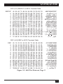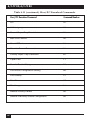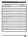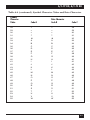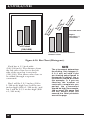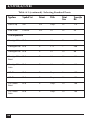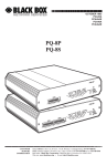
1
FEBRUARY 2000 PCD50A PCD50AE PCD51A PCD51AE A/C-7P RO A/C-7S RO P RO A/C-7 I SW1 I O O 7 8 5 6 3 4 1 2 SW2 SW1 I O On Data r Data From l Powe r te m Prin n Fro t Paralle O Hos Off Hoste Lin c Line n y S S RO A/C-7 I On l Seria ower Data Data P r te m Prin n Fro t Out O Hos Off Hoste Lin c Line Syn O 7 8 5 6 3 4 1 2 7 8 5 6 4 3 1 2 CUSTOMER Order toll-free in the U.S. 24 hours, 7 A.M. Monday to midnight Friday: 877-877-BBOX SUPPORT FREE technical support, 24 hours a day, 7 days a week: Call 724-746-5500 or fax 724-746-0746 INFORMATION Mail order: Black Box Corporation, 1000 Park Drive, Lawrence, PA 15055-1018 Web site: www.blackbox.com • E-mail: [email protected] A/C-7P RO, A/C-7S RO FEDERAL COMMUNICATIONS COMMISSION AND INDUSTRY CANADA RADIO FREQUENCY INTERFERENCE STATEMENTS This equipment generates, uses, and can radiate radio frequency energy and if not installed and used properly, that is, in strict accordance with the manufacturer’s instructions, may cause interference to radio communication. It has been tested and found to comply with the limits for a Class A computing device in accordance with the specifications in Subpart J of Part 15 of FCC rules, which are designed to provide reasonable protection against such interference when the equipment is operated in a commercial environment. Operation of this equipment in a residential area is likely to cause interference, in which case the user at his own expense will be required to take whatever measures may be necessary to correct the interference. Changes or modifications not expressly approved by the party responsible for compliance could void the user’s authority to operate the equipment. This digital apparatus does not exceed the Class A limits for radio noise emission from digital apparatus set out in the Radio Interference Regulation of Industry Canada. Le présent appareil numérique n’émet pas de bruits radioélectriques dépassant les limites applicables aux appareils numériques de classe A prescrites dans le Règlement sur le brouillage radioélectrique publié par Industrie Canada. 3 A/C-7P RO, A/C-7S RO NORMAS OFICIALES MEXICANAS (NOM) ELECTRICAL SAFETY STATEMENT INSTRUCCIONES DE SEGURIDAD 1. Todas las instrucciones de seguridad y operación deberán ser leídas antes de que el aparato eléctrico sea operado. 2. Las instrucciones de seguridad y operación deberán ser guardadas para referencia futura. 3. Todas las advertencias en el aparato eléctrico y en sus instrucciones de operación deben ser respetadas. 4. Todas las instrucciones de operación y uso deben ser seguidas. 5. El aparato eléctrico no deberá ser usado cerca del agua—por ejemplo, cerca de la tina de baño, lavabo, sótano mojado o cerca de una alberca, etc.. 6. El aparato eléctrico debe ser usado únicamente con carritos o pedestales que sean recomendados por el fabricante. 7. El aparato eléctrico debe ser montado a la pared o al techo sólo como sea recomendado por el fabricante. 8. Servicio—El usuario no debe intentar dar servicio al equipo eléctrico más allá a lo descrito en las instrucciones de operación. Todo otro servicio deberá ser referido a personal de servicio calificado. 9. El aparato eléctrico debe ser situado de tal manera que su posición no interfiera su uso. La colocación del aparato eléctrico sobre una cama, sofá, alfombra o superficie similar puede bloquea la ventilación, no se debe colocar en libreros o gabinetes que impidan el flujo de aire por los orificios de ventilación. 10. El equipo eléctrico deber ser situado fuera del alcance de fuentes de calor como radiadores, registros de calor, estufas u otros aparatos (incluyendo amplificadores) que producen calor. 11. El aparato eléctrico deberá ser connectado a una fuente de poder sólo del tipo descrito en el instructivo de operación, o como se indique en el aparato. 4 A/C-7P RO, A/C-7S RO 12. Precaución debe ser tomada de tal manera que la tierra fisica y la polarización del equipo no sea eliminada. 13. Los cables de la fuente de poder deben ser guiados de tal manera que no sean pisados ni pellizcados por objetos colocados sobre o contra ellos, poniendo particular atención a los contactos y receptáculos donde salen del aparato. 14. El equipo eléctrico debe ser limpiado únicamente de acuerdo a las recomendaciones del fabricante. 15. En caso de existir, una antena externa deberá ser localizada lejos de las lineas de energia. 16. El cable de corriente deberá ser desconectado del cuando el equipo no sea usado por un largo periodo de tiempo. 17. Cuidado debe ser tomado de tal manera que objectos liquidos no sean derramados sobre la cubierta u orificios de ventilación. 18. Servicio por personal calificado deberá ser provisto cuando: A: El cable de poder o el contacto ha sido dañado; u B: Objectos han caído o líquido ha sido derramado dentro del aparato; o C: El aparato ha sido expuesto a la lluvia; o D: El aparato parece no operar normalmente o muestra un cambio en su desempeño; o E: El aparato ha sido tirado o su cubierta ha sido dañada. 5 A/C-7P RO, A/C-7S RO TRADEMARKS Centronics® is a registered trademark of GENICOM Corporation. Epson® is a registered trademark of Seiko Epson Corporation. IBM®, Proprinter®, and IPDS™ are registered trademarks or trademarks of IBM Corporation. Hewlett-Packard®, HP®, LaserJet®, and PCL® are registered trademarks of Hewlett-Packard. OKIDATA® is a registered trademark of Oki America, Inc. Mannesmann Tally® is a registered trademark of Mannesmann Tally Corporation. All applied-for and registered trademarks are the property of their respective owners. 6 A/C-7P RO, A/C-7S RO Contents Chapter Page 1. Specifications...................................................................................................9 2. Introduction ..................................................................................................10 2.1 Description of Front Panels .................................................................11 2.2 About this User’s Guide .......................................................................11 2.3 Unpacking.............................................................................................11 3. Installation.....................................................................................................13 Power On/Off Sequence ............................................................................15 4. Configuration ................................................................................................20 4.1 A/C-7 RO Configuration .....................................................................20 4.2 Configuration Switch Settings .............................................................21 4.3 Setup Software (does not apply to versions after Feb. 1996).............26 4.4 Host/PC Download Command Overview ...........................................27 4.5 Restoring Factory Defaults ...................................................................57 5. Operation .....................................................................................................58 5.1 Printer Sharing .....................................................................................58 5.2 Parallel/Serial Port Initialization ........................................................59 5.3 Host Port Initialization.........................................................................59 5.4 Print Position and Page Length...........................................................59 5.5 Laser Printing .......................................................................................60 5.6 Computer Output Reduction (COR) .................................................61 5.7 Automatic Print Orientation (APO) ...................................................62 5.8 Generic Mode .......................................................................................64 6. Advanced Features ........................................................................................66 6.1 Command PassThru.............................................................................66 6.2 Custom User Strings.............................................................................67 6.3 SCS Mode Transparent Data ...............................................................67 6.4 Color Printing.......................................................................................68 6.5 Printing Bar Codes ...............................................................................68 6.6 I-O Graphics Language ........................................................................84 6.6.1 I-O Graphics Language Overview .............................................84 6.6.2 Helpful Hints..............................................................................88 6.6.3 Basic Description........................................................................90 7 A/C-7P RO, A/C-7S RO 6.7 I-O Graphic Language (IOGL) in Action.........................................101 6.7.1 General Steps............................................................................101 6.7.2 Tutorial .....................................................................................101 6.7.3 X- and Y-Axes............................................................................105 6.8 Linking Graphical Output to a Host Application ............................106 6.9 Printing Images from the Host..........................................................107 7. Troubleshooting .........................................................................................109 7.1 Interface Self-Test...............................................................................109 7.2 EBCDIC Hex Dump ...........................................................................110 7.3 ASCII Hex Dump ...............................................................................111 7.4 Problem Resolution Guide ................................................................112 Appendix A: Font (FGID) Reference for HP LaserJet Printers ..................117 Appendix B: Character Sets...........................................................................141 Appendix C: Serial Port Pinnings .................................................................144 Appendix D: Parallel Port Pinnings..............................................................146 Appendix E: Transferring Power to Pin 18 ..................................................148 8 A/C-7P RO, A/C-7S RO 1. Specifications Emulation—IBM® 3812, 4214, 4224, 3287, 3262, and 3268 printers (non-IPDS) Systems Supported—ASCII printer, IBM® 30XX, 43XX, 937X host, or 3174, 3274, or 3276 controller Indicators—(5) LEDs: Power, Host line, Sync, Printer Online, Data from Host, Data Out Connectors—PCD50A, PCD50AE: (1) BNC, (1) DB25 female, (1) 36-pin Centronics®; PCD51A, PCD51AE: (1) BNC, (1) DB25 female, (1) DB25 male Power—9 VAC wallmount transformer Size—6.5"H x 2.1"W x 5.1"D (16.5 x 5.3 x 13 cm) Weight—3 lb. (1.4 kg) 9 A/C-7P RO, A/C-7S RO 2. Introduction The A/C-7P RO and the AC-7S RO are powerful, yet easy-to-operate external printer interfaces. You can easily set them up through on-board configuration switches or Host/PC download commands. The A/C-7P RO and A/C-7S RO attach virtually any ASCII printer to an IBM 30XX, 43XX, 937X host, or 3174, 3274 or 3276 controller. They offer reliable emulations of IBM 3812, 4214, 4224, 3287, 3262 and 3268 printers (all non-IPDS™). When connected to a laser printer operating in PCL® mode, the A/C-7 RO allows Computer Output Reduction (COR) and Automatic Page Orientation (APO). In addition, paper can be pulled from several sources and a multitude of fonts (printer-resident or from optional cartridges) are supported. The A/C-7P RO comes with a standard parallel sharing port that allows automatic sharing of the attached printer between the host and a PC or LAN. The A/C-7S RO comes with a standard serial sharing port. A/C-7P RO SW1 I Host Printer Data Data On From From Line Sync Line Host Parallel I O ON Power O 12345678 OFF A/C-7S RO I SW1 SW2 O I Host Printer Data Serial On From Data Line Sync Line Host Out ON Power O 12345678 12345678 Figure 2-1. Front Panels of the A/C-7 RO. 10 OFF A/C-7P RO, A/C-7S RO 2.1 Description of Front Panels CONFIGURATION SWITCHES The Configuration Switches are used to set the output protocol and to perform the available test and diagnostic functions. While the A/C7P RO models come with only one bank of switches, the A/C-7S RO comes with two banks of eight switches. The left bank is labeled SW1; the right bank is labeled SW2. • Power—The A/C-7 RO is powered on. On/Off Switch—The On/Off switch is used to power on or power off the A/C-7 RO. Use this switch when asked to cycle power. 2.2 About This User’s Guide Since this user’s guide covers two A/C-7 RO models, including A/C-7P RO and A/C-7S RO. LEDS 2.3 Unpacking The green LED lights indicate the following: • Host Line Sync—Communication lines between the host and the interface are established. • Printer Online—The printer is ready to receive data. Check the packaging for water or physical damage, and notify the carrier immediately if there is any damage. Keep the original packaging in case you need to move or ship the A/C-7 RO. • Data From Host—The A/C-7 RO is currently processing data received from the coax host. • Data From Parallel/Serial—The A/C-7 RO is currently receiving data from an attached PC or LAN. PC download commands are processed, other data is transmitted to the printer. 11 A/C-7P RO, A/C-7S RO The package should include the following: • A/C-7P RO or A/C-7S RO • Wallmount transformer (9V AC output) • Standard parallel cable (for A/C-7P RO only) • Standard serial cable (for A/C-7S RO only) 12 A/C-7P RO, A/C-7S RO 3. Installation Before connecting the A/C-7 RO to the printer, verify that the printer functions properly by performing a printer self-test. Consult the printer’s user’s guide for instructions on how to start and evaluate the self-test. If the printer functions properly, proceed with the installation of the A/C-7 RO. WARNING Electrical current from power lines and cables connecting the A/C-7 RO, printer, and PC can be hazardous. To minimize the danger, follow the instructions below. NOTE 4. If the sharing port of the A/C-7P RO is used, attach the parallel cable now. Note that a PC or LAN connected to the A/C-7P RO’s sharing port should always be powered up when the A/C-7P RO is operating. 5. Connect the wall mount transformer from the outlet to the A/C-7P RO’s “9V” connector. Connect the power cord(s) to the printer and PC (if used). 6. Power on the A/C-7P RO, then printer. The A/C-7P RO’s green LED lights labeled “Power” and “Printer On Line” should be lit. 1. Power off the printer and PC (if used) and disconnect the power cord(s). 7. Print an A/C-7P RO self-test. Power off the A/C-7P RO. Set configuration switch SW1:8 (far right) to the “|” position. Power on the A/C-7P RO. After the self-test prints, set configuration switch SW1:8 back to the “o” position, then cycle the power one more time. 2. Use the configuration switches located on the A/C-7P RO’s front panel to select the desired output protocol. Refer to Table 4.1 for configuration switch settings. 8. Refer to the self-test printouts to determine which configuration parameters need to be altered. Change these parameters by using the Host/PC download commands. 3. Connect the parallel cable from the interface’s “Parallel Out” connector to the printer’s parallel port. 9. With the A/C-7P RO powered off, attach the coax cable from the host to the A/C-7P RO’s BNC connector. Do not connect the interface to the coax cable until Step 9. To install the A/C-7P RO: 13 A/C-7P RO, A/C-7S RO NOTE Whenever the printer is powered off, the A/C-7P RO must also be powered off to ensure they stay in sync with each other. To install the A/C-7S RO: 1. Power off the printer and PC (if used) and disconnect the power cord(s). 2. Use the configuration switches on the A/C-7S RO’s front panel to select the desired output protocol and the serial output parameters for the interface. Refer to Tables 4.1 and 4.5 for configuration switch settings. 3. Connect the serial cable from the A/C-7S RO’s “Serial Out” connector to the printer’s serial port. 4. If the sharing port is used, attach a second serial cable to the A/C7S RO’s “Serial In” port. Note that a PC or LAN connected to the A/C-7S’s sharing port should always be powered on when the A/C-7S RO is operating. In addition, the PC/LAN and the interface must be using the same serial parameters. Refer to Section 5.1, Printer Sharing, for more information. 5. Connect the wall mount transformer from the outlet to the A/C-7S RO’s “9V” connector. Connect the power cord(s) to the printer and PC (if used). 14 6. Power on the A/C-7S RO, then the printer. The A/C-7S RO’s green LED lights labeled “Power” and “Printer On Line” should be on. If the sharing port is used and handshaking requirements are met, the LED labeled “PC/LAN Ready” should also be on. 7. Print an A/C-7S RO self-test. Power off the interface, then set configuration switch SW1:8 (far right on the first switch bank) to the “|” position. (If you are operating a label printer, put the printer in ASCII hex dump mode, then power on the A/C7S RO. If the label printer starts printing, the A/C-7S RO has passed the self-test. To obtain a printout of the current settings, connect the A/C-7S RO to a laser or dot-matrix printer.) Power on the A/C-7S RO. After the self-test prints, set configuration switch SW1:8 back to the “o” position, then cycle the power one more time. 8. Refer to the self-test printouts to determine which configuration parameters need to be altered. Change these parameters by using the Host/PC download commands. Refer Chapter 4 for further information. A/C-7P RO, A/C-7S RO 9. With the A/C-7S RO powered off, attach the coax cable from the host to the A/C-7S RO’s BNC connector. NOTE Whenever the printer is powered off, the A/C-7S RO must also be powered off to ensure they stay in sync with each other. To power on: 1. Turn on the printer. 2. Turn on the A/C-7 RO. To power off: 1. Turn off the A/C-7 RO. 2. Turn off the printer. The self-test printouts in Figures 31 and 3-2 show the default settings for the different A/C-7 RO models. The printout you obtain may differ from the samples, since only the configuration parameters associated with the active output protocol (e.g. HP PCL, IBM PPDS, etc.) are printed. The second page of the selftest printout is the same for both A/C-7 RO models. POWER-ON/OFF SEQUENCE Follow the power-on and -off sequences exactly, or the print output may be garbled. 15 A/C-7P RO, A/C-7S RO Self-Test Printout - A/C-7P RO PARALLEL 3270 COAX INTERFACE COPYRIGHT (c) 1994 SDE Corp Rom Ok Ram Ok Software Version 1.00 ASCII Printer Protocol : Generic #01 #02 #03 #04 #05 #06 #07 #08 #12 #13 #14 - Buffer Size (Characters) Lines Density (LPI) Characters Density (CPI) Line Spacing Form Length (MPL) Maximum Print Position (MPP) Print Case LU1 Language FF Before Local Screen Copy FF After Local Screen Copy: LU3 Print Image (Non-SCS Mode): : : : : : : : : : 0 No 2 1920 6 10 1 Single (6 or 8 LPI) 066 080 1 Dual 01 English (US) 0 No #15 #16 #17 #18 #19 #20 #21 #25 #26 #27 #30 #31 #34 #36 #37 #39 #40 #41 #42 #45 #50 #51 #65 #56 SP: #57 HP CR at MPP + 1 NL at MPP +1 Valid FF Followed by Data Valid FF at End of Buffer FF Valid Location : Auto Function at End of Job Print Quality (Fast Draft) IBM Motion Command Suppress Empty Forms Form Feed After Time Out : Override of Formatting Cmds Truncate/Wrap select Interv Required (IR) Timeout Suppress IBM Control Codes Vertical Channel Select (VCS) CPT End Delimiter (ASCII) CPT Start Delimiter (ASCII) Command ID Char (ASCII) Start/Stop Buffer Hex Dump SCS TRN Translate Sharing Port Timeout Host Port Timeout Character Set Selection Parallel Port Init String 0 LU3 and Local Copy Null line suppress : 0 Next line : 0 Current line + 2 : 0 2nd PP : 1 Line 1 0 FF valid at 1st PP or MPP+1 : 0 NL : 0 DP=Fast Draft, Text= Draft : 0 Use FF : 0 No 0 No : 0 Disabled : Wrap text beyond MPP : 120 times 5 seconds : 0 No control codes suppressed : 1 3268/4224 : 2625 (&%) : 2625 (&%) : 5A (Z) : 0 No Action : 1 3287 emulation, SCS code 35 : 08 Seconds : 08 Seconds : 1 Roman 8 : Host Port Init String : Figure 3-1. Self-Test Printout for A/C-7P RO. 16 A/C-7P RO, A/C-7S RO Self-Test Printout - A/C-7S RO SERIAL 3270 COAX INTERFACE COPYRIGHT (c) 1994 SDE Corp Rom Ok Ram Ok Software Version 1.00 ASCII Printer Protocol Serial Out Baud Rate Serial Out Parity Serial Out Word Length Serial Out Stop Bits : : : : : Generic 9600 Baud None 8 Bits 1 Bit #01 #02 #03 #04 #05 #06 #07 #08 #12 #13 #14 - Buffer Size (Characters) Lines Density (LPI) Characters Density (CPI) Line Spacing Form Length (MPL) Maximum Print Position (MPP) Print Case LU1 Language FF Before Local Screen Copy FF After Local Screen Copy: LU3 Print Image (Non-SCS Mode) : : : : : : : : : 0 No : 2 1920 6 10 1 Single (6 or 8 LPI) 066 080 1 Dual 01 English (US) 0 No #15 #16 #17 #18 #19 #20 #21 #25 #26 #27 #30 #31 #34 #36 #37 #39 #40 #41 #42 #45 #50 #51 - CR at MPP + 1 NL at MPP +1 Valid FF Followed by Data Valid FF at End of Buffer FF Valid Location : Auto Function at End of Job Print Quality (Fast Draft) IBM Motion Command Suppress Empty Forms Form Feed After Time Out : Override of Formatting Cmds Truncate/Wrap select Interv Required (IR) Timeout Suppress IBM Control Codes Vertical Channel Select (VCS) CPT End Delimiter (ASCII) CPT Start Delimiter (ASCII) Command ID Char (ASCII) Start/Stop Buffer Hex Dump SCS TRN Translate Sharing Port Timeout Host Port Timeout 0 LU3 and Local Copy Null line suppress : 0 Next line : 0 Current line + 2 : 0 2nd PP : 1 Line 1 0 FF valid at 1st PP or MPP+1 : 0 NL : 0 DP=Fast Draft, Text=Draft : 0 Use FF : 0 No 0 No : 0 Disabled : Wrap text beyond MPP : 120 times 5 seconds : 0 No control codes suppressed : 1 3268/4224 : 2625 (&%) : 2625 (&%) : 5A (Z) : 0 No Action : 1 3287 emulation, SCS code35 : 08 Seconds : 08 Seconds Figure 3-2. Self-Test Printout for A/C-7S RO. 17 A/C-7P RO, A/C-7S RO #65 #76 #77 #78 #79 #56 SP: #57 HP: Character Set Selection Serial In Baud Rate Serial In Word Length Serial In Stop Bits : Serial In Parity Parallel Port Init String: : : : 1 Bit : 1 Roman 8 2 9600 Baud 8 Bits 0 None Host Port Init String: Figure 3-2. Self-Test Printout for A/C-7S RO, Page 1 (continued). 18 A/C-7P RO, A/C-7S RO SCS (LU1) EBCDIC to ASCII Translate Table EBCDIC 0 1 2 3 4 5 6 7 8 9 A B C D E F 40 50 20 26 20 C5 C0 C1 CC CD C8 C9 C4 D5 E2 D1 D4 DD B5 D9 B7 DE BF 21 2E 24 3C 2A 28 29 2B 3B 7C 5E 60 2D 2F A2 D8 A1 E0 E1 D0 B4 B6 7C 2C 25 5F 3E 3F 70 80 D6 D2 DC 61 A4 62 A5 63 A3 64 E5 65 A6 66 A7 67 E6 68 A9 69 3A FB 23 FD 40 E4 27 B2 3D F0 22 FE 90 B3 6A 6B 6C 6D 6E 6F 70 71 72 F9 FA D7 20 D3 BA A0 F3 7E 73 74 75 76 77 78 79 7A B8 B9 E3 B1 F1 20 B0 C0 D0 E0 F0 456789ABCDEF 5E 7B 7D 5C 30 &–øØ°µ^{ } \ 0 BB 41 4A 20 31 é / Éaj ~ £AJ 1 BC 42 4B 53 32 âêÂÊbks¥BKS2 F2 43 4C 54 33 äëÄËclt · CLT3 BE 44 4D 55 34 àèÀÈdmuƒDMU4 BD 45 4E 56 35 áíÁÍenv§ENV5 F4 46 4F 57 36 ãîÃÎfow¶FOW6 F7 47 50 58 37 åïÅÏgpx1/4GPX7 F8 48 51 59 38 çìÇÌhqy1/2HQY8 F5 49 52 5A 39 ñßÑ`irz3/4IRZ9 5B 2D 31 32 33 ¢ ! | : «ª ¡ [ –123 5D C2 C3 DF AE . $ ,#»º¿]ôûÔÛ B0 CE CF DA DB <*%@∂ æ D–öüÖÜ AB CA CB E8 AD ( ) _ ' y´ ,Y´ ¨òùÒÙ 27 C6 C7 E7 ED +;>= Æ ´óúÓÚ 5F EA EF E9 20 |^?"± _õÿÕ DSC (LU3) DBC to ASCII Translate Table DBC 0 1 2 3 4 5 6 7 8 9 A B C D E F 00 00 00 00 00 00 00 00 00 3E 3C 5B 5D 29 28 7D 7B 10 20 20 30 3D 31 27 32 22 33 2F 34 5C 35 7C 36 7C 37 3F 38 21 39 24 DE BF BD BB 23 BC 40 F2 25 BA 5F 30 26 2D 2E 2C 3A 2B 5E B0 B3 00 5E 7E AB 60 A9 00 40 50 60 70 C8 CC A1 D8 C9 CD A3 A5 D9 DD E6 A7 CA CE E8 DA CB CF AD DB E2 C0 E1 A2 EA C1 E9 A4 EF D1 59 A6 C8 C2 41 DF C9 C3 45 AE C5 C4 45 E0 D9 C5 49 DC CA D5 4F E5 CB C6 55 E7 CF C7 59 ED B5 B7 43 B6 80 61 62 63 64 65 66 67 68 69 6A 6B 6C 6D 6E 6F 70 90 71 72 73 74 75 76 77 78 79 7A D7 D6 D4 B5 3B 2A A0 41 42 43 44 45 46 47 48 49 4A 4B 4C 4D 4E 4F 50 B0 51 52 53 54 55 56 57 58 59 5A D3 D2 D0 B4 3B 2A 0123456789AB 0&àäÀÄaqAQ =1-èëÈËbrBR ' 2 . ìïÌÏcsCS " 3 , òöÒÖdtDT / 4 :ùüÙÜeuEU \5+ãâÃÂfvFV |6^õêÕÊgwGW |7–ÿîYÎhxHX >?8°àôAÔiyIY <!9 èûEÛjzJZ [$ß^éáEÁkæKÆ ]¢§~ìéIÉløLØ )£#"òíOÍmåMÅ (¥@'ùóUÓnçNÇ }·%`üúYÚo;O; { _ çñCÑp*P* Figure 3-3. Self-Test Printout, Page 2. 19 A/C-7P RO, A/C-7S RO 4. Configuration 4.1 A/C-7 RO Configuration The A/C-7 RO can be configured through its on-board configuration switches or by sending download commands from the host or from a PC/LAN. To ensure proper functioning of your A/C-7 RO, you should review all available parameters. 20 A/C-7P RO, A/C-7S RO 4.2 Configuration Switch Settings Use the A/C-7 RO’s configuration switches to select the output protocol and to perform the available test and diagnostic functions. Use a pointed object, such as a ball-point pen, to change the switch settings. NOTE If an invalid switch setting is encountered at power-up, all LED lights will blink and the A/C-7 RO cannot operate. When operating, the A/C-7 RO will only recognize EBCDIC Hex Dump and ASCII Dump settings. All other settings are read only at powerup. Whenever you change one of these settings, remember to cycle the power to activate them. 21 A/C-7P RO, A/C-7S RO Table 4-1. Configuration Switch Settings. Output Protocol SW1:4 SW1:5 SW1:6 SW1:7 Hewlett-Packard® PCL o o | o IBM Proprinter o | o | IBM PPDS o o o o Epson ESC/P1 o o o | Epson DFX+ o | | | Epson LQ (24-pin) o | | o Epson 9-pin (DFX) | o o o Generic | o o | 22 A/C-7P RO, A/C-7S RO Table 4-2. Tests/Diagnostic. Tests/Diagnostic SW1:1 SW1:8 Restore Factory Defaults | o Self-Test o | EBCDIC Hex Dump o | Table 4-3. Tests/Diagnostic. Tests/Diagnostic SW1:4 SW1:5 SW1:6 SW1:7 ASCII Hex Dump | | | | Table 4-4. Operating Mode. Operating Mode No Tests SW1:1 SW1:4 SW1:5 SW1:6 SW1:7 SW1:8 o Valid Output Protocol o The first two test functions (Restore Factory Defaults and SelfTest) are performed only if the configuration switches are set as indicated when the A/C-7 RO is powered on. In the case of the selftest, the A/C-7 RO prints a self-test at power-on and then needs to be powered off. Refer to Chapter 7 for more information. 23 A/C-7P RO, A/C-7S RO The second (right) bank of switches of the A/C-7S RO is used to set up the A/C-7S RO for communication with the printer. Table 4-5. Serial Out Baud-Rate Switches. Serial Out Baud Rate SW2:1 SW2:2 SW2:3 38,400 o o o 19,200 o o | 9,600 o | o 4,800 o | | 2,400 | o o 1,200 | o | 600 | | o 300 | | | 24 A/C-7P RO, A/C-7S RO Table 4-6. Serial Out Word-Length Switch. Serial Out Word Length SW2:4 7 Bits o 8 Bits | Table 4-7. Serial Out Stop Bits Switch. Serial Out Stop Bits SW2:5 1 Bit o 2 Bits | Table 4-8. Serial Out Parity Switch. Serial Out Parity SW2:6 SW2:7 None o o Odd o | Even | 0 Table 4-9. Serial X-On/X-Off Switch. Serial X-On/X-Off SW2:8 Send | Don’t Send o 25 A/C-7P RO, A/C-7S RO 4.3 Setup Software (does not apply to versions after February 1996) Older versions of the A/C-7 RO included a setup disk. For newer versions (after February 1996), all configuration parameters not already covered through configuration switches can be changed through the host/PC download commands. NOTE For a description of the available configuration parameters, refer to the Table 4-11, Host/PC Download Commands. 4.4 Host/PC Download Commands By sending download commands from the Host/PC to the A/C-7 RO, you can change all configuration parameters not already covered through the configuration switches. Most Host/PC download commands are placed in a Host/PC document or on the screen. Regardless of whether the incoming print job is a screen print, a spreadsheet, or a word-processing document created on either the host or PC, the A/C-7 RO will recognize the Host/PC download command. The command itself will not be printed if it was entered correctly. If any part of the command is printed, the A/C-7 RO did not recognize the command because of a problem in the format. Check the syntax of the command and send the command again. Most Host/PC download commands sent to the A/C-7 RO take effect immediately and stay only in the A/C-7 RO’s active memory. To save the changed configuration beyond a power off, send Host/PC download command Z99,0. Tip: Save the Host/PC download commands in a separate file. If you need to re-configure the A/C-7 RO at a later time, or if you need to configure more than one A/C-7 RO, just “print” the file containing your Host/PC download commands. Take the following steps to enter a host download command. 26 A/C-7P RO, A/C-7S RO 1. Type the Command Pass-Thru delimiter &% (or alternate CPT beginning delimiter) in the document at the point where the command is to take effect. 2. Type an upper case “Z” (or the alternate command ID character). 3. Type the command number for the command to be used, as shown in the table. 4. Type a comma. 5. Type the value representing the desired selection. No spaces are allowed. A space or invalid character in a command causes the A/C-7 RO to ignore the command and resume printing from the point the error occurred. 7. Multiple commands can be chained together by using a slash (/) or backslash (\) to separate the commands (no spaces allowed). For example, to set the Form Length (Command 05) to 64 lines (Value 64), the Buffer Size (Command 01) to 960 characters (Value 1), and the Character Density (Command 03) to 12 CPI (Value 12), type: &%Z05,64/Z01,1/Z03,12 4.4 Host/PC Download Command Overview Table 4-10 shows the Coax Host/PC Download commands and their corresponding command numbers in alphabetical order: 6. A space or control character (NL, LF, CR, or FF) signals the end of the download command. 27 A/C-7P RO, A/C-7S RO Table 4-11. Host/PC Download Commands. 28 Host/PC Download Command Command Number 10 CPI Command String 86 12 CPI Command String 88 15 CPI Command String 87 16.7 CPI Command String 89 6 LPI Command String 84 8 LPI Command String 85 Alternate Paper Tray Orientation 63 CPT Ending Delimiter 39 CPT Start Delimiters 40 Automatic Function at End of Job 20 Automatic Print Orientation 61 Buffer Hex Dump 42 CPI 03 Character Set 65 Coax Buffer Size 01 A/C-7P RO, A/C-7S RO Table 4-11 (continued). Host/PC Download Commands. Host/PC Download Command Command Number Command ID Character 41 CR at MPP + 1 15 Custom User Strings 55 EpsonMatrixFont 09 FF After Time Out 27 FF At End Of Buffer 18 FF After Local Screen Copy 13 FF Before Local Screen Copy 12 Form Length 05 Host Port Init String 57 Host Timeout 51 IBM Motion Command 25 Intervention Required Timeout 34 Laser Paper Size 32 Line Spacing 04 29 A/C-7P RO, A/C-7S RO Table 4-11 (continued). Host/PC Download Commands. 30 Host/PC Download Command Command Number LPI 02 LU1 Language 08 Manual Paper Tray Orientation 64 Max Print Position 06 NL at MPP+1 16 Override Format Commands 30 Primary Paper Tray Orientation 62 Paper Path 11 Parallel Port Init String 56 Print Active Configuration Setting 98 Print Quality 21 Print Case 07 Print Image 14 Restore Factory Default 98 Restore Previously Saved Configuration 98 A/C-7P RO, A/C-7S RO Table 4-11(continued). Host/PC Download Commands. Host/PC Download Command Command Number Save Config in NV Memory 99 SCS Translate = 45 Serial In Baud Rate (serial only) 76 Serial In Parity (serial only) 79 Serial In Stop Bits (serial only) 78 Serial In Word Length (serial only) 77 Serial Port Init String (serial only) 58 Sharing Timeout 50 Suppress Empty Forms 26 Suppress Host 36 Text After FF 17 True LPI Spacing 38 Truncate/Wrap 31 Valid FF Location 19 Vertical Channel Select 37 31 A/C-7P RO, A/C-7S RO Asterisks (*) identify factorydefault settings. Invalid commands (such as selecting 2 LPI) are ignored. The last valid setting will be unchanged. Examples in this section apply to configuration through Host/PC download only. COMMAND 1: BUFFER SIZE COMMAND 2: LINES PER INCH Selects default LPI. VALUE 3 4 *6 8 Selects logical default buffer size. VALUE 1 *2 3 4 5 DESCRIPTION 960 characters 1920 characters 2560 characters 3440 characters 3564 characters NOTES This command, along with the Z99,0 command, changes the logical buffer size selection in the nonvolatile memory of the interface. The logical buffer size is only reported to the host the next time the unit is powered on. The physical buffer size is permanently set at 4K. Example: &%Z1,3 sets logical buffer size to 2560 characters. DESCRIPTION 3 LPI 4 LPI 6 LPI 8 LPI NOTES This default emulates the front panel selection on an IBM printer. The IBM host can control the LPI unless Command 36 is used to override the host LPI commands. Example: &%Z2,8 sets the printer to 8 LPI default. COMMAND 3: CHARACTERS PER INCH Selects default CPI. VALUE 0 *10 12 15 16 DESCRIPTION No default sent to printer 10 CPI 12 CPI 15 CPI 16.7 CPI NOTE The IBM host can control CPI unless Command 36 is used to select override of host CPI commands. Example: &%Z3,15 sets the printer to 15 CPI default. *Factory-default setting. 32 A/C-7P RO, A/C-7S RO COMMAND 4: LINE SPACING COMMAND 6: MAXIMUM PRINT POSITION Selects default Line Spacing. VALUE *1 2 DESCRIPTION Single Space Double Space Example: &%Z4,2 sets the printer to double space default. COMMAND 5: FORM LENGTH Selects default Form Length (MPL = Maximum Print Lines). VALUE 000 001 to 255 *066 DESCRIPTION No form length control Set form length in number of lines Factory Default NOTE The 000 value enables the front panel selection on the printer to control the form length when Command 25 is set to value 0. Example: &%Z5,70 sets form length to 70 lines for A4 paper. Selects current and default Maximum Print Position, the maximum number of characters which can be printed on each line. VALUE 000 001 to 254 DESCRIPTION Infinite line length Set MPP in number of characters *80 Factory Default NOTES Normal values are 80, 132, or 198 characters. This default emulates the front-panel selection on an HP printer. MPP and the current position will not be changed by changes in CPI. The infinite line length will place no limits on the number of characters that can be sent to the printer on a single line. Example: &%Z6,63 sets MPP to 63 characters. *Factory-default setting. 33 A/C-7P RO, A/C-7S RO COMMAND 7: PRINT CASE Selects default print case. VALUE 0 *1 DESCRIPTION Mono case Dual case NOTE This default only affects LU3 printing. 23 (same as 07) 24 (same as 09) 25 (same as 01) 26 (same as 08) 27 (same as 10) 28 29 (same as 06) 30 (same as 11) Example: &%Z7,0 sets default to mono case. COMMAND 8: LU1 LANGUAGE Selects default LU1 language. VALUE * 01 DESCRIPTION English (U.S.) EBCDIC 03 Austrian/German 04 Belgian 05 Brazilian 06 Canadian (French) 07 Danish/Norwegian 08 Danish/Norwegian (alt.) 09 Finnish/Swedish 10 Finnish/Swedish (alt.) 11 French 12 (same as 11) French (alt.) 13 Austrian/German (alt.) 14 International Set 5 15 Italian 16 Japanese (English) 19 Spanish 20 Spanish (alt.) 21 Spanish Speaking 22 English (U.K.) *Factory-default setting. 34 31 (same as 14) 32 (same as 14) Norwegian Swedish EBCDIC (alt.) Norwegian (alt.) Swedish (alt.) Portuguese Canadian (Bilingual) French AZERTY (105 character) Swiss German Swiss French NOTES This command, along with command Z99,0, changes the default LU1 language selection in the permanent memory of the interface. The command value should match the language number used in IBM CU configuration sequence number 121. Example: &%Z8,04 sets LU1 language to Belgian. A/C-7P RO, A/C-7S RO COMMAND 9: EPSON MATRIX FONT Selects Epson default font, if supported by the printer. VALUE *1 2 3 4 5 6 7 DESCRIPTION Draft Print Quality Roman, NLQ Sans Serif, NLQ Courier, NLQ Prestige, NLQ Script, NLQ OCR-B, NLQ Example: &%Z9,2 selects near-letter quality (Roman) as the default. alternate bin 1 is default (corresponds to PCL escape value 4) 4 Envelope feeder default 5 Manual sheet feed default 6 Manual envelope feed default 7 Epson DFX front tray 8 Epson DFX rear tray 9 Cut sheet feeding from alternate bin 2 is default (corresponds to PCL escape value 5) COMMAND 11: PAPER PATH Selects default paper path for the Page Presentation Media (PPM) command. VALUE 0 DESCRIPTION Ignore the host PPM command and select the paper tray through the printer’s front panel. 1 Tractor feed or only one paper source used (ignore the host PPM). *2 Cut sheet feeding from primary bin is default. 3 NOTES This command defines the default paper source for the Page Presentation Media (PPM) command in SCS mode. If the PPM command is received from the host, the interface always sends the paper source to the printer unless value 0 or 1 is selected. The printer ignores the command if it does not have a secondary paper bin or an envelope feeder. A manual sheet feed Cut-sheet feeding from *Factory-default setting. 35 A/C-7P RO, A/C-7S RO command in the SCS PPM causes the printer to wait for the operator to insert paper in the manual feed tray. This command takes effect immediately if placed on the first position of the page (line 1, position 1); otherwise, it takes effect on the next page. Example: &%Z11,5 selects manual sheet feed as the default source of paper. COMMAND 13: FORM FEED AFTER LOCAL SCREEN COPY Specifies whether a form feed is performed after a local screen hard copy. VALUE *0 1 COMMAND 12: FORM FEED BEFORE LOCAL SCREEN PRINT Specifies whether a form feed is performed before doing local screen print. VALUE *0 1 DESCRIPTION No form feed before local screen print Form feed before local screen print NOTE This command only affects the local screen copy function, not the hostinitiated local copy printing, and functions only in LU3 (non-SCS) operations. Example: &%Z12,1 performs a FF before local screen print. *Factory-default setting. 36 DESCRIPTION No Form Feed after local screen dump Form Feed performed after local screen dump NOTE To use this function, the RPQ should be: IBM 3268 RPQ SC9508 IBM 3287 RPQ MC3750 IBM 4214 OPT 20=3 This command only affects the local screen copy, not the host-initiated local copy printing, and functions only in LU3 (non-SCS) operations. Example: &%Z13,1 performs a FF after local screen copy. COMMAND 14: LU3 PRINT IMAGE (Non-SCS Mode) Selects Null-Line Suppression or True Screen Image in LU3 printing mode. VALUE *0 DESCRIPTION Null line suppression in local copy and non-SCS print A/C-7P RO, A/C-7S RO 1 2 True screen image in nonSCS print and null-line suppression in local copy 3 True screen image in nonSCS print and true screen image in local copy NOTES To use this function, the RPQ should be: IBM 3268 RPQ SC9505 IBM 3287 RPQ SC3741 IBM 4214 OPT 18=2 Available only in LU3 (nonSCS) operations. Values 0 and 1 are only functional from CUT terminals. Example: &%Z14,3 prints true screen image in non-SCS print and local copy. COMMAND 15: CR at MPP + 1 Sets the printer in accordance with the RPQ installed in the control unit. VALUE *0 1 NOTES Null-line suppression in non-SCS print and true screen image in local copy DESCRIPTION First print position (PP) of next line First PP of current line To use this function, the RPQ should be: IBM 3268 RPQ SC9501 IBM 3287 RPQ S30219 IBM 4214 OPT 15=1 Available only in LU3 (nonSCS) operation. Example: &%Z15,1 prints first PP of current line as the next PP when a CR is received at MPP+1. COMMAND 16: NL at MPP + 1 Sets the printer in accordance with the RPQ installed in the control unit. VALUE *0 1 DESCRIPTION First PP of current line + 2 lines First PP of next line NOTES To use this function, the RPQ should be: IBM 3268 RPQ SC9502 IBM 3287 RPQ S30219 IBM 4214 OPT 15=1 Available only in LU3 (nonSCS) operation. Example: &%Z16,1 performs first PP of next line as the next PP when an NL is received at MPP+1. *Factory-default setting. 37 A/C-7P RO, A/C-7S RO COMMAND 17: VALID FF FOLLOWED BY DATA NOTES To use this function, the RPQ should be: IBM 3268 RPQ SC9504 IBM 3287 RPQ SC3749 IBM 4214 OPT 17=2 Sets the printer in accordance with the RPQ installed in the control unit. VALUE *0 1 DESCRIPTION Second print position of first line on next form First print position (PP) of first line on next form NOTES For the Value 1 selection, the RPQ would be: IBM 3268 RPQ SC9503 IBM 3287 RPQ N/A IBM 4214 OPT 16=2 Available only in LU3 (nonSCS) operation. Example: &%Z17,1 performs first PP of first line on next form as the next PP when a valid FF is not positioned at the end of an IBM print buffer. COMMAND 18: VALID FF AT END OF PRINT BUFFER Sets the printer in accordance with the RPQ installed in the control unit VALUE 0 *1 DESCRIPTION First PP of second line on next form First PP of first line on next form *Factory-default setting. 38 Available only in LU3 (nonSCS) operation. Example: &%Z18,1 performs first PP of first line on next form as the next PP when a valid FF is received at the end of an IBM print buffer. COMMAND 19: FF VALID LOCATION Sets the printer in accordance with the RPQ installed in the control unit. VALUE *0 1 DESCRIPTION FF is valid only at the first print position or at position MPP+1. FF is valid anywhere it occurs. NOTES To use this function, the RPQ should be: IBM 3268 RPQ SC9506 IBM 3287 RPQ SC3739 IBM 4214 OPT 19=1 Available only in LU3 (nonSCS) operation. Example: &%Z19,1 makes FF valid anywhere it occurs. A/C-7P RO, A/C-7S RO COMMAND 20: AUTOMATIC FUNCTION AT END OF JOB COMMAND 21: PRINT QUALITY (FastDraft) Sets the printer in accordance with the RPQ installed in the control unit. Defines default print quality. VALUE *0 DESCRIPTION NL is automatically executed after the buffer is completed (unless a FF, NL, or CR was last in the buffer). 1 FF is automatically executed after the print buffer is completed (unless a FF was last in the buffer). NOTES To use this function, the RPQ should be: IBM 3268 RPQ SC9507 IBM 3287 RPQ SC3740 IBM 4214 OPT 20=2 VALUE *0 DESCRIPTION The Page Presentation Media (PPM) commands control the quality: DP Quality (01) = FastDraft and DP Text Quality (02) = normal draft. 1 All DP draft output is printed FastDraft All DP draft output is printer normal draft Value 0 reversed, 01 = normal and 02 = FastDraft All output is Near Letter Quality 2 3 4 Example: &%Z21,1 selects all DP output as FastDraft printing. Available only in LU3 (nonSCS) operation. Do not press the form feed or line feed buttons on the front of the printer. This will cause the host and printer to lose synchronization of paper position. This command reduces the need to advance the paper. Example: &%Z20,1 sets the printer to issue a FF automatically at the end of the print buffer. *Factory-default setting. 39 A/C-7P RO, A/C-7S RO COMMAND 25: IBM MOTION COMMANDS Enables a Form Feed from the host system to be converted to the required number of line feeds (beneficial when forms length is controlled by the interface). VALUE *0 DESCRIPTION Pass FF from host to the printer 1 Count the lines in Command 5 and send multiple line feeds to the printer in place of the host FF 2 Ignore all IBM Motion Commands Example: &%Z25,1 sets the printer to count the lines specified in Command 5. COMMAND 26: SUPPRESS EMPTY FORMS Suppresses blank printout pages caused by form feed commands that occur at the top of a form. VALUE *0 1 DESCRIPTION No, do not suppress empty forms Yes, suppress empty forms *Factory-default setting. 40 NOTES If 1 is selected, the interface ignores form feed commands located at the top of form position. This command affects printing in both DSC and SCS modes. This differs from the IBM 3287, which suppresses form feed only in DSC mode. Example: &%Z26,1 sets the interface to suppress empty forms. COMMAND 27: FF AFTER TIME ELAPSE Sends a Form Feed if unprinted data remains in the print buffer for the coax-port timeout interval specified in Command 51. VALUE *0 1 DESCRIPTION No extra FF is sent Send FF after timeout value NOTE In most cases, the host application generates a termination FF and there is no need to change this command from the default. Example: &%Z27,1 sends a FF after time delay selected by command 51 (default = 5 sec.) when unprinted data remains in the print buffer. A/C-7P RO, A/C-7S RO COMMAND 30: OVERRIDE OF FORMATTING COMMANDS COMMAND 31: TRUNCATE/WRAP SELECT Enables the printer’s front-panel selections to control how a job is printed. Printers without HP PCL only. Selects whether the interface truncates or wraps the text if the maximum print position is exceeded. VALUE *0 1 DESCRIPTION Normal operation (disabled) Formatting commands are not sent to the printer (enabled) VALUE *0 DESCRIPTION Allow text to print on next line when maximum print position is exceeded 1 Truncate text beyond the maximum print position NOTES When active, this command overrides the interface’s default selections for CPI, LPI, font, orientation, bin selection, paper size, COR, and line compression. A reset command is sent to the printer before a coax print job in order to restore the printer’s front-panel default selections. This command has no effect on the special features Command Pass-Thru, user strings, initialization strings, and coax host RPQs. Example: &%Z30,1 sets override of formatting commands. Example: &%Z31,1 causes text that exceeds the maximum print position to be truncated (not printed). COMMAND 32: PAPER SIZE HP PCL only. Specifies the paper size used for printing. VALUE *0 1 2 3 4 5 *Factory-default setting. DESCRIPTION Selects 8 1/2" x 11" letter paper Selects A4 (210mm x 297mm, 8.27" x 11.69") paper Selects 8 1/2" x 14" legal paper Selects 11" x 17" paper Selects A3 size paper Printer selected Example: &%Z32,1 selects A4 paper. 41 A/C-7P RO, A/C-7S RO COMMAND 34: INTERVENTION REQUIRED (IR) TIMEOUT NOTES If this command is set to 1, documents need to be formatted by sending transparent control codes to the printer using Command Pass-Thru or SCS mode transparent data. Sets the time interval before an intervention required signal is sent to the host after a printer error occurs. VALUE 000 DESCRIPTION Never send an IR 001 to 255 IR is sent (value *5) seconds after printer error occurs *120 Default, send IR after ten minutes. Example: &%Z34,036 sets IR time interval to 3 minutes (36 *5)/60 = 3 minutes. COMMAND 36: SUPPRESS IBM CONTROL CODES This function is used to select suppression of all or some IBM control codes sent from the host system. VALUE *0 1 2 3 4 5 DESCRIPTION Obey all IBM control codes Suppress all IBM control codes Suppress LPI, CPI, MPP and MPL control codes Suppress CPI and MPP control codes Suppress LPI and MPL control codes Suppress print quality specified in the PPM command *Factory-default setting. 42 If value 2 is selected, the SCS pitch (CPI), line density (LPI), SHF (MPP), and SVF (MPL) commands will be suppressed (not sent to the printer). Example: &%Z36,2 no LPI, CPI, MPP or MPL commands are sent to the printer. The document prints using the printer’s defaults. COMMAND 37: VERTICAL CHANNEL SELECT (VCS) Specifies vertical channel select (VCS) emulation. Functions similarly to a vertical tab, except the 3287 does LF only. VALUE 0 *1 DESCRIPTION 3287 VCS emulation 3268/4214/4224 VCS emulation Example: &%Z37,0 selects 3287 VCS emulation. A/C-7P RO, A/C-7S RO COMMAND 38: TRUE LPI SPACING COMMAND 39: CPT ENDING DELIMITER CHARACTERS HP PCL only. Because laser printers have a non-printable border around the edge of single-sheet pages, 6 LPI and 8 LPI spacing is compressed slightly to enable 66 lines and 88 lines to be printed on 11-inch long paper. This can occasionally cause a problem, especially when using preprinted forms that must align precisely. Command 38 enables a user to override the laser-printer LPI compression. Specifies the two characters to be used for the ending delimiter characters for Command Pass-Thru. VALUE *0 1 DESCRIPTION Compress the vertical LPI spacing Print using true 6 and 8 LPI spacing NOTE If true LPI is selected, the user needs to adjust the document formats to allow for the reduced number of lines that can be printed per page, or the extra lines may print onto another sheet of paper. Example: &%Z38,1 specifies that vertical spacing prints using true 6 and 8 LPI. VALUE XXYY DESCRIPTION XX is the ASCII hexadecimal value of the first character and YY is the ASCII hexadecimal value of the second character. NOTES If an ending delimiter is not selected with this command, the delimited selected with Command 40 will be used as a default. The default delimiter will no longer be active if the command is used to change it. If Command 39 and Command 40 are both entered, Command 39 must be sent after Command 40 to be active. One delimiter character can be specified instead of two by entering the hex code for the character followed by two zeros (for example, &%Z39,2500 selects & as the delimiter). A hex code that starts with 00 is invalid. *Factory-default setting. Example: &%Z39,253F specifies the %? characters as the alternate ending delimiter characters (% ASCII hex value is 25 and ? ASCII hex value is 3F). 43 A/C-7P RO, A/C-7S RO COMMAND 40: CPT START DELIMITER CHARACTERS Specifies the two characters to be used for the beginning delimiter characters for Command Pass-Thru. VALUE XXYY DESCRIPTION XX is the ASCII hexadecimal value of the first character and YY is the ASCII hexadecimal value of the second character NOTES Host download commands use the CPT beginning delimiter characters as well. The new character(s) replace the &% in front of the Z. If you do not select an ending delimiter with Command 39, the delimiter selected with this command will be used as the default ending delimiter. The default beginning delimiter will no longer be active if you use this command to change it. One delimiter character can be specified instead of two by entering the hex code for the character followed by two zeros (for example, &%Z40,2500 selects & as the delimiter). A hex code that starts with 00 is invalid. *Factory-default setting. 44 Example: &%Z40,253F specifies the %? characters as the beginning delimiter characters (% ASCII hex value is 25 and ? ASCII hex value is 3F). COMMAND 41: COMMAND ID CHARACTER Specifies the character that is used for the command identifier that follows the delimiter characters. VALUE 00 DESCRIPTION Deletes the previously selected character ZZ ZZ is the ASCII hex value of the command ID character NOTE The character selected must be a hex value (L, P, or U). Example: &%Z41,59 specifies “Y” as the command ID character. A/C-7P RO, A/C-7S RO COMMAND 42: START AND STOP EBCDIC HEX DUMP COMMAND 45: SCS TRN TRANSLATE After receiving a start command the coax interface, starting with the next buffer received, sends all host data directly to the printer as hexadecimal printing until a stop command is received or the printer is powered off. Specifies how transparent data sent using SCS code 35 is handled. VALUE *0 1 2 DESCRIPTION No action taken Start EBCDIC hex dump Stop EBCDIC hex dump NOTES This command enables the user to print only the section of the document that is in question in buffer hex dump format. Hex printing starts with the buffer after the start command and stops with the buffer after the stop command. Examples: &%Z42,1 starts buffer hex dump printing; &%Z42,2 stops buffer hex dump printing. VALUE 0 *1 DESCRIPTION Binary Transparent Emulate IBM 3287 Printer NOTES Value 1 causes valid graphic characters to be printed normally (i.e., converted from EBCDIC to ASCII), while control codes and invalid graphics are printed as hyphens, and normal page formatting is maintained. Value 0 causes the 8-bit binary codes to be sent directly to the printer just as they are received from the host. SCS code 36 functions the same as code 35. Available in SCS (LU1) mode only. Example: &%Z45,0—All SCS Code 35 data is sent to the printer as binary codes without translation. *Factory-default setting. 45 A/C-7P RO, A/C-7S RO Use of the DOS PRINT command or a spooling program for the PC is recommended. COMMAND 50: SHARING PORT TIMEOUT Selects the time interval that the interface waits for receipt of additional data from the alternate (PC/LAN) host before automatically switching to check for data from the coax host. VALUE 04 to 63 DESCRIPTION Time interval in number of seconds *08 Factory default is 8 seconds NOTES The interface sends a reset command to the printer and restores the coax host defined format commands (i.e., LPI, PI, MPL, MPP) prior to printing data from the coax host after having printed data from the shared parallel port. Because the printer is being shared between the parallel port and the 3270 host, careful attention should be paid to setting up the PC so that jobs are not automatically terminated because the printer is busy. This problem may be helped by setting the PC timer “off” by writing “mode 1pt1:,,;” (in case of an LPT1 printer) in DOS. If your printer supports Intelligent Emulation Switching (IES), make sure the printer’s IES timeout period is less than the command 51 timeout setting. Example: &%Z50,10 sets the timeout interval to 10 seconds COMMAND 51: HOST PORT TIMEOUT Selects the time interval that the interface waits for receipt of additional data from the coax host before automatically switching to check for data from the alternate (PC/LAN) host. VALUE DESCRIPTION 04 to 60 Time interval in number of seconds *08 Factory default is 8 seconds NOTES The alternate (PC/LAN) host is responsible for sending any needed format commands required by the printer prior to sending printable data. If your printer supports Intelligent Emulation Switching (IES), make sure the printer’s IES timeout period is less than the command 50 timeout setting. *Factory-default setting. 46 A/C-7P RO, A/C-7S RO COMMAND 55: CUSTOM USER STRINGS COMMAND 56: PARALLEL PORT INITIALIZATION STRING Allows the user to define up to six custom user strings, of up to 25 bytes each, which are stored in the memory of the interface and sent to the printer whenever the character delimiter, letter U, and number of the string appears in the text of the document (for example, &%U3). Allows the user to define an initialization string of up to 25 bytes, which is stored in the memory of the interface and is sent to the printer at the beginning of any printing received from the parallel port. VALUE 0-5(max. 25 bytes of ASCII hex code) 0-5() DESCRIPTION Defines the custom user string Deletes custom user string NOTES To aid in readability, a single space is allowed between hex bytes, but is not included in the string. VALUE 1(max. 25 bytes of ASCII hex code) 1() DESCRIPTION Defines the parallel port init string Deletes the parallel port init string NOTES To aid in readability, a single space is allowed between hex bytes but is not included in the string. The strings could specify a special font-selection command or other custom command to be sent directly to the printer. The string could specify a special font-selection command or other custom command to be sent directly to the printer prior to the data that is received from the parallel shared port. This command, if placed as the first printable data at the top of the page (position 1, line 1), will be sent to the printer prior to the data. To change the initialization string, simply input the new command values. The entire old string is automatically erased. To change a custom user string, simply input the new custom user string values; the old string is automatically erased. To delete the initialization string from the NV memory, simply put nothing between the parentheses. Example: &%Z55,3(1B01) Defines the &%U3 custom user string to send an “Escape and SOH” (1B and 01 hex) to the printer, which is the double wide command.) Example: &%Z56,1( ) deletes from NV memory any hex string that had been previously defined for the parallel-port initialization string. 47 A/C-7P RO, A/C-7S RO COMMAND 57: HOST PORT INITIALIZATION STRING Allows the user to define an initialization string of up to 25 bytes, which is stored in the memory of the interface and is sent to initialize the printer for host printing after shared-port printing has occurred. The interface also restores the host page-format parameters after sending this string and prior to host printing. The initialization string is sent at the beginning of each page. VALUE 1(max. 25 bytes of ASCII hex code) 1() DESCRIPTION Defines the hostport init string Deletes the hostport init string NOTES To aid in readability, a single space is allowed between hex bytes but is not included in the string. The host-port initialization string is only sent to the printer when you turn the printer on and after printing by the shared parallel port has occurred. Host SCS commands and download commands have priority over the initialization string instructions. To change the initialization string, simply input the new command values. The old string is automatically erased. 48 To delete the initialization string from the permanent memory, simply type the parentheses with nothing between them. Example: &%Z57,1( ) deletes from permanent memory any hex string that had been previously defined for the host-port initialization string COMMAND 58: SERIAL-PORT INITIALIZATION STRING Allows the user to define an initialization string of up to 25 bytes, which is stored in the memory of the interface and is sent to the printer at the beginning of any printing received from the serial port. VALUE 1(max. 25 bytes of ASCII hex code) 1() DESCRIPTION Defines the serialport init string Deletes the serialport init string NOTES To aid in readability, a single space is allowed between hex bytes but is not included in the string. The string could specify a special font-selection command or other custom command to be sent directly to the printer prior to the data that is received from the serial shared port. A/C-7P RO, A/C-7S RO To change the initialization string, simply input the new command values. The entire old string is automatically erased. NOTE APO active is the recommended selection. A user can manipulate the page dimensions using SCS commands to control the orientation of the printing as long as the page size required is 8 1/2 x 11" or smaller. To delete the initialization string from the NV memory, simply put nothing between the parentheses. Example: &%Z58,1( ) deletes from NV memory any hex string that had been previously defined for the serial port initialization string. COMMAND 61: AUTOMATIC PRINT ORIENTATION (APO) HP PCL only. Laser printers have the ability to automatically control page orientation if the user decides to activate Auto Print Orientation (APO). Refer to the APO flowchart (Figure 5-1) in Section 5.3. VALUE 0 DESCRIPTION APO is NOT ACTIVE. Print orientation is controlled by the orientation selections specified in Commands 62, 63, and 64. *1 APO is ACTIVE. The page dimensions of a document are checked to determine if the data should be printed in landscape because the width is greater than the length. Example: &%Z61,1 enables APO COMMAND 62: PRIMARY PAPER TRAY ORIENTATION HP PCL only. The SCS (LU1) PPM command specifying the source for the paper can have a printing orientation assigned to the paper tray that is assigned. Refer to the APO flowchart (Figure 5-1) in Section 5.7. This command duplicates the IBM 3812 and 4028 printer’s feature with the additional selection of option 3 below. VALUE *0 DESCRIPTION Computer Output Reduction (COR) Mode is active when paper is specified to be selected from the primary tray 1 Prints PORTRAIT orientation using the active font when the primary tray is specified 2 Prints LANDSCAPE orientation using the active font when the primary tray is specified 49 A/C-7P RO, A/C-7S RO 3 User Defined mode. Documents are printed using the fonts and orientation that the user specifies through use of the &% font ID commands. Example: &%Z62,3 specifies that the document is printed as formatted when the primary paper tray is specified as the paper source. COMMAND 63: ALTERNATE PAPER TRAY ORIENTATION HP PCL only. This command functions identically to Command 62 except it controls the orientation for printing that specifies the alternate tray for the paper source. NOTE The value 3 is an excellent choice when COR is not required, since the user can decide the fonts and orientation he desires by using &% font ID commands. Example: &%Z63,2 specifies that landscape orientation will be used for all printing in which the SCS (LU1) PPM code specifies the alternate paper tray be used. COMMAND 64: MANUAL FEED TRAY ORIENTATION HP PCL only. This command functions identically to Command 62 except it controls the orientation for printing when the PPM Command specifies the manual feed tray for the paper source. Even if the printer does not have an alternate paper tray, the SCS (LU1) host specifies the alternate tray, and the interface prints the document in accordance with the selection in Command 63. Values are the same as Command 62 except substitute “manual feed tray” in place of “primary tray” in the descriptions. Values are the same as Command 62 except substitute “alternate tray” for “primary tray” in the descriptions. The laser printer will, upon receipt of the manual feed tray command, not print until paper is placed into the manual feed slot. This allows the user to insert special forms, letter head, or colored paper into the manual feed slot. *Factory-default setting. 50 NOTE A/C-7P RO, A/C-7S RO character-set selection is changed. Example: &%Z64,1 specifies that all printing using paper from the manual feed slot will be printed in portrait orientation. Refer to the character set summary tables at the end of the self test to confirm which ASCII character is printed for each of the 3270 hex codes. Both the EBCDIC and DSC tables are provided. COMMAND 65: CHARACTER SET SELECTION Enables the user to select the ASCII character set that is used in the conversion from EBCDIC (SCS/LU1) or DSC (LU3) to ASCII. This selection automatically changes to match the output protocol selected through the interface’s configuration switches if HP, PPDS, or Proprinter II modes are chosen. The other selections require the user to manually select the appropriate character set. VALUE 1 2 3 DESCRIPTION Roman 8 character set (HP PCL) Code Page 850 character set (IBM PPDS, Epson ESC/P2, Generic) IBM PC Extended (Code Page 437) and Epson Graphics (PC Set 2) Example: &%Z65,2 selects the Code Page 850 character set. COMMAND 70: OVERWRITE EBCDIC (SCS/LU1) TRANSLATION TABLE Custom substitutions defined by this command and stored in permanent memory are written into the EBCDIC (SCS/LU1) to ASCII translation table. VALUE XX DESCRIPTION The EBCDIC character to be changed (in hex) YY The substitute ASCII character for the EBCDIC character above NOTES NOTES The character-set substitutions defined in Commands 70 and 71 must be adjusted if the ASCII character set is changed. Previously stored substitutions are automatically changed to the new selection when the same hex location is specified in the EBCDIC table. All previously defined substitutions are lost from NV memory when the 51 A/C-7P RO, A/C-7S RO Previously stored substitutions are cancelled if an ASCII hex sequence of 00 is specified. Command Z99,0 must be used to store the substitutions in permanent memory for them to be effective when the printer is next turned on. The active EBCDIC (SCS/LU1) translation table prints out at the end of the interface self-test summary. Example: &%Z70,7B,40/Z99,0 prints a 40 ASCII hex (a @ symbol) when the interface receives an EBCDIC 7B (a # symbol). The command is followed by a command Z99,0 which stores the active setup selections in permanent memory. COMMAND 71: OVERWRITE DSC (LU3) TRANSLATION TABLE Custom substitutions defined by this command, and stored in the permanent memory, are overwritten into the DSC (LU3) to ASCII translation table. NOTES This command functions similarly to Command 70 except the substitutions are applicable to the DSC (LU3) translation table. Refer to the Command 70 instructions. 52 The active DSC (LU3) translation table prints out at the end of the interface selftest summary. COMMAND 76: SERIAL-IN BAUD RATE Selects the Baud Rate for data received at the serial-in port. A new setting will not be effective immediately. To activate the new setting, cycle power on the interface. VALUE 0 1 *2 3 4 5 6 7 DESCRIPTION 38,400 baud 19,200 baud 9,600 baud 4,800 baud 2,400 baud 1,200 baud 600 baud 300 baud Example: &%Z76,0 sets the receiving baud rate to 38,400 A/C-7P RO, A/C-7S RO COMMAND 77: SERIAL-IN WORD LENGTH COMMAND 79: SERIAL-IN PARITY Selects the Word Length of data received at the serial-in port. A new setting will not be effective immediately. To activate the new setting, cycle power on the interface. Selects the Parity of a data stream received at the serial-in port. A new setting will not be effective immediately. To activate the new setting, cycle power on the interface. VALUE 7 *8 DESCRIPTION 7 Bits 8 Bits Example: &%Z77,7 sets the word length to 7 bits COMMAND 78: SERIAL-IN STOP BITS Selects the number of Stop Bits of a data stream received at the serial-in port. A new setting will not be effective immediately. To activate the new setting, cycle power on the interface. VALUE *1 2 DESCRIPTION 1 Bit 2 Bits Example: &%Z78,2 sets the number of Stop Bits to 2 VALUE *0 1 2 DESCRIPTION None Odd Even Example: &%Z79,2 sets the parity to even. COMMAND 84: 6 LPI STRING Used when operating in Generic output protocol. Defines the 6 LPI string the interface sends to the printer when the host sends a 6 LPI command. VALUE 1(max. 25 bytes of ASCII hex code) 1() DESCRIPTION Defines the 6 LPI string Deletes the 6 LPI string *Factory-default setting. 53 A/C-7P RO, A/C-7S RO NOTES This string represents the printer-specific command to set the printer to 6 LPI. Consult your printer’s manual for the appropriate hex value representing the 6 LPI command. Example: &%Z84,1(1B 32) stores the 6 LPI command for an Epson LQ-2500 printer (hex value 1B 32) as the 6 LPI string. COMMAND 85: 8 LPI STRING Used when operating in Generic output protocol. Defines the 8 LPI string the interface sends to the printer when the host sends an 8 LPI command. VALUE 1(max. 25 bytes of ASCII hex code) 1() DESCRIPTION Defines the 8 LPI string Deletes the 8 LPI string NOTES This string represents the printer-specific command to set the printer to 8 LPI. Consult your printer’s *Factory-default setting. 54 manual for the appropriate hex value representing the 8 LPI command. Example: &%Z85,1(1B 30) stores the 8 LPI command for an Epson LQ-2500 printer (hex value 1B 30) as the 8 LPI string. COMMAND 86: 10 CPI STRING Used when operating in Generic output protocol. Defines the 10 CPI string the interface sends to the printer when the host sends a 10 CPI command. VALUE 1(max. 25 bytes of ASCII hex code) 1() DESCRIPTION Defines the 10 CPI string Deletes the 10 CPI string Example: &%Z86,1(1B 50) stores the 10 CPI command for an Epson LQ-2500 printer (hex value 1B 50) as the 10 CPI string. A/C-7P RO, A/C-7S RO COMMAND 87: 15 CPI STRING COMMAND 89: 16.7 CPI STRING Used when operating in Generic output protocol. Defines the 15 CPI string the interface sends to the printer when the host sends a 15 CPI command. Used when operating in Generic output protocol. Defines the 16.7 CPI string the interface sends to the printer when the host sends a 16.7 CPI command. VALUE 1(max. 25 bytes of ASCII hex code) 1() DESCRIPTION Defines the 15 CPI string Deletes the 15 CPI string VALUE 1(max. 25 bytes of ASCII hex code) 1() DESCRIPTION Defines the 16.7 CPI string Deletes the 16.7 CPI string Example: &%Z87,1(1B 67) stores the 10 CPI command for an Epson LQ-2500 printer (hex value 1B 67) as the 15 CPI string. Example: &%Z89,1(1B 10) stores the 16.7 CPI command for an Epson LQ-2500 printer (hex value 1B 10) as the 16.7 CPI string. COMMAND 88: 12 CPI STRING COMMAND 98: RESTORE DEFAULTS OR PRINT CONFIGURATION Used when operating in Generic output protocol. Defines the 12 CPI string the interface sends to the printer when the host sends a 12 CPI command. VALUE 1(max. 25 bytes of ASCII hex code) 1() DESCRIPTION Defines the 12 CPI string Restores the factory default configuration selections, prints out a copy of the active configuration selections, or restores the permanent memory selections to the active setup status. VALUE 0 DESCRIPTION Restores the factory setup 1 Prints out the active setup selections 2 Restores the setup selections stored in the permanent memory to active status Deletes the 12 CPI string Example: &%Z88,1(1B 4D) stores the 10 CPI command for an Epson LQ-2500 printer (hex value 1B 4D) as the 12 CPI string. 55 A/C-7P RO, A/C-7S RO NOTES If a document is printed using temporary host download commands (commands not stored using the Z99,0 command), value 2 will restore the permanent memory selections. Put a &%Z98,2 at the end of the document to restore the standard setup parameters for the next user of the printer. The active setup and permanent memory setup selections are the same after a Command Z99,0 or a Command Z98,2 is sent to the printer. Example: &%Z98,1 prints out the active setup selections for review. COMMAND 99: STORE CONFIGURATION IN PERMANENT MEMORY Send this command after all desired host download configuration commands have been sent to the interface. It stores the active setup in the permanent memory of the interface so it will be in effect whenever the printer is powered on. Otherwise, active configuration commands are lost when the printer is turned off. VALUE 0 DESCRIPTION To complete the command, the value 0 must be used NOTES Host download selections followed by a Command Z99,0 will be stored in permanent memory and active when the printer is turned on. Only use Command Z99,0 when the host download selection needs to be permanently stored in the memory of the interface. Example: &%Z99,0 stores the currently active setup selections in the permanent memory of the interface. 56 A/C-7P RO, A/C-7S RO 4.5 Restoring Factory Defaults The factory-default configuration can be restored either by sending Host/PC Download Command “Z98,0” or by taking the following steps: 1. Power off the printer and the A/C-7 RO. 2. Disconnect the host and PC sharing cables from the interface. 4. Power on the A/C-7 RO. The factory defaults are restored. The LED lights labeled “Host Ready” and “Printer Ready” will blink continuously, indicating the A/C-7 (RO) is not in operating mode. 5. Power off the A/C-7 RO and return configuration switch SW1:1 (on the first bank of switches) to the “o” position. Switch SW1:8 should be in the “o” position as well. 3. Set configuration switch SW1:1 (far left) to the “|” position, and switch SW1:8 (far right of the first bank of switches) to the “o” position if it is not already there. 57 A/C-7P RO, A/C-7S RO 5. Operation 5.1 Printer Sharing The A/C-7P RO and A/C-7S RO allow the printer to be shared automatically between an attached PC/LAN and an IBM coax host. Simply connect the PC/LAN printer server to the parallel/serial port. The A/C-7P RO can supply external devices attached to its parallel sharing port with 5V up to 350 mA. See Appendix E for instructions on how to transfer power to pin 18 on the A/C-7P RO. The A/C-7 RO uses a timeout after each print job before it honors print jobs from another port. At the end of a host print job, the A/C-7P RO waits for the specified Host Port Timeout period before it honors data streams coming in through the parallel port. The Host Port Timeout period is set through Host/PC download command 51. After a parallel or serial print job is completed, the A/C-7 RO will again wait for a period of time before it honors host print jobs. The Sharing Port Timeout is set through Host/PC download command 50. 58 If the PC print job is sent while a host job is printing, the printer responds as “busy” to the PC print request. The print job can be spooled through a spool program, sent to the printer when the host job is finished or if the PC’s printer port is set for infinite retry through the DOS “Configure Printer” command (described in the DOS manual), the print job waits for the printer to be available to receive the data. By default, the A/C-7S RO sends data at 96N81 (9,600 baud; parity = none; word length = 8 bits; stop bits = 1). Make sure that the printer and the A/C-7S RO are using the same serial parameters. The A/C-7S RO’s Serial-Out parameters can be changed using the second (right) bank of switches located on the front panel. Also make sure that the A/C-7S RO’s Serial-In settings are the same as those of the PC/LAN. Note that when printing from the share por, the slowest baud rate (Serial-In, Serial-Out) will determine the print speed. The A/C-7S RO’s Serial In parameters can be changed through Host/PC download commands 76 through 79. A/C-7P RO, A/C-7S RO PC printing longer than 10 to 20 minutes (depending on host configuration) may cause the 3270 host to drop communication with the printer (“go to sleep”). The output protocol specified in the A/C-7S RO’s configuration (through configuration-switch settings) is irrelevant for printing from the shared port. For PC/LAN printing, select the appropriate printer driver on the PC/LAN printer server. 5.2 Parallel/Serial-Port Initialization If you want to change the printer’s configuration for shared printing (e.g. set it to PostScript mode), use the parallel- or serial-port initialization string (Host/PC download command 56 for parallel; command 58 for serial). Consult the printer’s user’s guide for the ASCII hex values representing the desired configuration commands. Then store these commands in the A/C-7 RO’s memory using Host/PC download commands 56 or 58. After the host printing is completed and before the print job from the shared port is sent to the printer, the A/C-7 RO will send this initialization string to the printer and configure it according to your instructions. However, it is possible that the print job coming through the parallel or serial shared port contains other printer instructions, thus overriding the parallel initialization string. 5.3 Host Port Initialization After shared printing, the A/C-7 RO reconfigures the printer according to the active configuration settings. If you want to further modify the printer configuration (e.g select a different font for all host printing) take advantage of the host port initialization string. Unlike the parallel- or serial-port initialization string, which is usually overridden by commands coming with the PC/LAN print job, the host-port initialization string is not sent to the printer until after the A/C-7 RO has reconfigured the printer for host printing. The initialization string is sent at the beginning of each printed page. 5.4 Print Position and Page Length Table 5-1 outlines the PMPP (Physical Maximum Print Position) and PMPL (Physical Maximum Page Length) for letter, legal, and A4 size paper. 59 A/C-7P RO, A/C-7S RO Table 5-1. PMPP and PMPL. PMPP at 10 12 CPI CPI 15 CPI PMPL at 17.1 6 CPI LPI 8 LPI True LPI True LPI Letter Portrait Landscape COR 80 105 136 96 126 154 120 157 201 136 178 201 66 50 66 88 87 89 63 48 — 84 84 — Legal Portrait Landscape 80 135 96 162 120 202 136 230 84 50 112 67 81 48 108 64 A4 Portrait Landscape 78 112 93 134 117 167 133 191 70 49 93 66 67 47 89 62 Paper Size 5.5 Laser Printing SELECTING FONTS You can select a printer-resident font or a font from an optional font cartridge in the printer by entering a font change command in the document. The font change commands take the following format: &%[P or L][font ID] 60 The &% (or the alternate beginning delimiter selected with command 40) is the delimiter that signals the A/C-7 RO that the information following is a command. The letter “P” or “L” controls the orientation of the printing: P for portrait and L for landscape printing. The font ID number selects the font to be used for printing. The font ID should be five digits in length. Refer to Appendix A for a list of fonts and their font IDs available for the printer. A/C-7P RO, A/C-7S RO For example: &%L00086 selects a Prestige 12 CPI font in landscape orientation. The font ID number must select a font available in the printer or in the installed cartridge. If the proper cartridge is not installed, or the font does not exist on the cartridge, then the printer will automatically select an alternate font for printing. Multiple font changes can be made in a document as long as all fonts are in the same orientation. Changes in orientation (portrait or landscape) automatically eject the page. A font ID that changes the orientation from the previous page must be on the first line and first position of the page or a blank page will be ejected. A blank page at the first of a print job is often caused by a change in orientation. Command 61 must be set to “1” (APO Disabled), Commands 62-64 must be set to “3” (User Defined). 5.6 Computer Output Reduction (COR) Computer Output Reduction (COR) is an IBM printer feature that automatically rotates data processing reports to landscape orientation and compresses the text to fit 198 columns x 66 lines on the page. COR is enabled by doing the following: 1. Select APO active with command 61 (value 0). 2. Select COR for the paper source with commands 62-64 (value 0). When COR is enabled, the following format changes are automatically made to data processing reports: • The page is printed in landscape orientation. • Vertical line height is 70% of that specified. • A 0.5-inch blank area is provided on the top and left edge of the paper. • The selected pitch is changed: 10 pitch to 13.3 pitch; 12 pitch to 15 pitch; 15 pitch to 19 pitch. 61 A/C-7P RO, A/C-7S RO A combination of control codes in the printer data stream and the settings in the configuration are used to determine page orientation when processing DSC, DSE, or LU1 (SCS) data streams. Some applications will not allow you to insert the data stream commands required to select orientation and format. Where the insertion of the required data stream commands is not possible, you can select the orientation and format desired by using the printer configuration settings. Use of the Write Control Character (WCC) in the DSC/DSE data streams for orientation and format selection is not recommended. 5.7 Automatic Print Orientation (APO) When Automatic Print Orientation (APO) is activated (command 61, value 1), the A/C-7 (RO) notes the format of the print image and calculates the required print dimensions. Figure 5-1 shows how the page size determines the orientation for coax COR. If a calculated paper size is larger than 8 1/2" x 11", the paper-tray orientation selection (commands 6264) determines the orientation. In LU3 (DSC/DSE) mode, the values used in the calculations are specified by the A/C-7 RO’s active 62 configuration selections. In LUl (SCS) mode, the values are specified in the data stream by the SCS controls. If a value has not been set in the SCS data stream, the A/C-7 RO’s active configuration is used instead. The APO feature also uses the calculated print width and length to determine the print orientation when the dimensions are less than 8 1/2" x 11". When the width is greater than the length and APO is active, the document prints in landscape, even if the font is specified as portrait. The following steps describe printing with the APO feature (refer to Figure 5-1). 1. If APO is not active (command 61, value 0), the A/C-7 RO uses the paper source selections (commands 62-64) to control orientation in the active font. If APO is active, the report continues to block 2. 2. The A/C-7 RO calculates the page size. If the page size is more than 8 1/2" x 11" the interface uses the paper source selections to control the orientation in the active font. If the report is less than 8 1/2" x 11" it continues to block 3. 3. At block 3, the interface checks the length and width. If the report is longer than it is wide, it prints in portrait. If the report is wider than it is long, the report prints in landscape. A/C-7P RO, A/C-7S RO START Page Orientation Logic 1 APO Active? (Command 61) No Print according to Paper Tray Orientation (Commands 62-64) Yes 2 COR Print Size Less Than 8 1/2 x 11? Portrait Landscape No User Defined Yes 3 Is Length Less Than Width? No Print in Portrait Print in Landscape Figure 5-1. Printing with the APO Feature. 63 A/C-7P RO, A/C-7S RO 5.8 Generic Mode The Generic output protocol should be used when the other output protocols of the A/C-7 RO are inappropriate. This could be the case with printers such as certain barcode label printers or embossers, but also with printers from Okidata®, Mannesmann-Tally®, etc. Refer to the printer’s user’s guide to find out if the printer operates with one of the output protocols of the A/C-7 RO. In Generic mode, the A/C-7 RO does not pass on the LPI and CPI commands from the host. Rather, it allows you to match the printer specific CPI or LPI command with the CPI or LPI command from the host (through Host/PC download commands 84-89). For example, the printer protocol a printer requires is not available on the A/C-7 RO. To change the printer to 10 CPI, the printer’s user’s guide provides the hexadecimal value of 1B 50. Use the Host/PC download command 88 to assign the value 1B 50 to the 10 CPI string: type &%Z88,1(1B 50). From now on, when the interface receives a request for 10 CPI from the host, it will send the value 1B 50 to the printer and thereby set it to 10 CPI. If nothing is assigned to the CPI or LPI string, the A/C-7 RO will send nothing to the printer—it will ignore the CPI or LPI command from the host. 64 The A/C-7 RO stores commands for the following CPI and LPI values: • 6 LPI—Host/PC download command 84 • 8 LPI—Host/PC download command 85 • 10 CPI—Host/PC download command 86 • 15 CPI—Host/PC download command 87 • 12 CPI—Host/PC download command 88 • 16.7 CPI—Host/PC download command 89 Other Printer Commands You can also enter commands into your document that allow you to control true LPI and response to host commands. These commands (shown in Table 5-2) are similar to font-change commands. A/C-7P RO, A/C-7S RO Table 5-2. Commands. Command Function ¬E Sends an ASCII ESC command to the printer ¬TY Enables true LPI printing ¬TN Disables true LPI printing ¬I Ignores all host formatting commands ¬S Stops ignoring host formatting commands The ¬E command allows you to send an escape command to the printer to control the printing. For example, ¬E(s3B would begin bold printing (see your printer’s manual for a list of the printer or escape commands). Use the ¬I and ¬S commands to remove unwanted host commands from a print file. For example, when printing with forms-generating software, the files are recognized by the host as text files and formatted with unwanted carriage returns and line feeds. The printer may compress line spacing to fit 66 lines onto the page. This may be undesirable, as when using pre-printed forms that must align correctly. In these cases, the ¬TY command prevents the printer from compressing the line spacing. Placing the ¬I at the end of a line and ¬S at the front of the next line causes the interface to remove the host carriage-return and line-feed commands and send only the data to the printer. 65 A/C-7P RO, A/C-7S RO 6. Advanced Features There are several advanced features in the A/C-7 RO for accessing special functions of the printers, which are not normally available on the IBM system printers: • Command Pass-Thru™ • Custom User Strings • SCS Mode Transparent Data • Bar Code Printing • Color Printing • I-O Graphics Language™ Each of these features is described below. 6.1 Command Pass-Thru™ The Command Pass-Thru feature allows access to all of the built-in features of your printer, even if these features aren’t normally available through the host software. Command Pass-Thru lets you place printer-specific command sequences into the data sent to the printer. The A/C-7 RO recognizes these special sequences and “passes the command through” to the printer. The steps below describe how to use Command Pass-Thru. 66 1. Find the command for the print feature in the printer’s user’s guide. 2. Convert the printer command to hexadecimal. 3. Place the beginning delimiter &% (or the custom delimiter as defined with command 40) in the document at the point you want the feature to take effect. This signals the start of the print feature. Enter the beginning printer command, then enter the ending delimiter &% (or the custom delimiter as defined with command 39). No spaces are allowed. 4. Move the cursor to the point in the text where you want to end the print feature. Enter the delimiter followed by the ending printer command and then the delimiter again, into the document. For example: The command ESC &d0D begins underlining and ESC &d@ ends underlining. First convert the start command to the hexadecimal 1B 26 64 30 44 and the ending command to 1B 26 64 40. And, if the delimiter is the default &% (hex 50 6C), then enter the commands as follows: A/C-7P RO, A/C-7S RO This is an &%1B26643044&%underlined&%1 B266440&% word. For example, use command 55 to define user string number 3 to send a form feed as follows (FF = 0C in hex): to print on the printer as: &%Z55,3(0C) This is an underlined word. NOTES Only numbers or the upper case letters A–F are allowed. Errors in the Command Pass-Thru sequence will cause the A/C-7 RO to ignore the command and resume printing at the point the error occurred. Command Pass-Thru may change the horizontal spacing. 6.2 Custom User Strings Host download command 55 allows you to define up to six (0 through 5) custom user strings. A user string can be a font ID, a form feed, or another printer command that is frequently used. After the custom user string is defined, the string is activated by placing the delimiter (&% or the beginning delimiter defined with command 40), a capital letter U, and the number of the desired custom user string into the text of a document. Then, to send a form feed at the end of a print job, enter the following at the end of the document: &%U3 Print the document, and the interface will send the 0C, or form feed, command to the printer when it encounters the &%U3 code. 6.3 SCS Mode Transparent Data SCS transparent mode (SCS TRN code 35) provides a method for transparent data transmission when operating in LU1 mode. To use this method, you must be connected to a system using SNA protocol and be operating as a Logical Unit Type 1. An SCS TRN sequence begins with a one-byte binary count immediately following the TRN code. The count indicates the number of bytes, not including the count byte, of transparent data to follow. Up to 256 bytes of transparent data can be sent in each sequence. 67 A/C-7P RO, A/C-7S RO SCS TRN data is user-defined is not scanned for SCS control codes. However, to emulate the characteristics of the IBM 3287, non-printable characters (control characters) are converted to hyphens. Data is translated to ASCII with undefined characters printed as hyphens. The A/C-7 RO offers a configurable option to emulate the IBM 3287 or to pass the data without translation. Refer to command 45, SCS TRN translate, on page for more detailed information. 6.4 Color Printing The A/C-7 RO allows printing of color on the HP Color LaserJet or DeskJet 1200C printers. Simply insert the color command in front of the text you want to colorize. Return to the “normal” black color by inserting _C00. The color commands are: ¬C00 - Black ¬C01 - Blue ¬C02 - Red ¬C03 - Magenta ¬C04 - Green ¬C05 - Turquoise/Cyan ¬C06 - Yellow ¬C07 - White ¬C08 - Black ¬C09 - Dark Blue ¬C10 - Orange _C15 - Grey ¬C11 - Purple _C16 - Brown ¬C12 - Dark Green ¬C13 - Dark Turquoise ¬C14 - Mustard 68 For example, to print the word “red” in the color red in the following sentence, type: This prints ¬C02red¬C00 in red. 6.5 Printing Bar Codes Using the bar-code feature, the following bar codes can be easily printed: Table 6-1. Bar Codes. Type Bar Code 1 Code 3 of 9 2 Code 128 3 Interleaved 2 of 5 4 POSTNET 5 UPC A 6 EAN 8 7 EAN 13 To print any of these bar codes, use the following format: ¬B<type>,<height>,<width>, <hr>,<chkd>,<ast>,<data>¬B A/C-7P RO, A/C-7S RO The bar-code command string must contain all of these parameters, even if the parameter is irrelevant for the type of bar code being printed. For example, POSTNET comes in only one size, so, any height or width specifications are ignored. But the parameters for height and width must be included anyway. <width>: Specifies the width of a bar code module. A module is defined as a specific combination of bars and spaces used to represent a humanreadable character. ¬B: Identifies the strings as a bar code command string. _B must be placed at the beginning and at the end of the string. Width parameters can range from 1 to 9 when printing to a PCL printer. When printing to an Epson or Proprinter mode dot-matrix printer, the width parameters can range from 1 to 3. <type>: Specifies the bar code type according to the table shown on the previous page. <height>: Specifies the height of the bar code. When using a PCL laser printer driver, height is expressed in multiples of 2.5 mm (approximately 1/10 inch). When operating in Epson or IBM Proprinter mode, height is expressed in multiples of 3.175 mm (1/8 inch). The height of the bar code can range from 1 (laser = 2.5 mm, dot-matrix = 3.175 mm) to 9 (laser = 22.5 mm, dot-matrix = 28.575 mm) inclusive. Height values are ignored if a POSTNET bar code is being printed, since POSTNET uses one standard height. However, a valid value (1-9) must be entered for the height parameter to ensure the bar-code command string is complete. By changing the width parameter, you can determine the width of the module and the thickness of the bars and spaces. To determine the total length of the bar code, simply multiply the module length (found in the table on the following page) by the number of bar-code characters. NOTE Be aware that the table gives rounded values only. Example: Using Code 3 of 9, you want to bar code the word “PRINTERS.” Assume the interface also generates a check digit and the start/stop characters. Setting the width parameter to 2 will yield a total bar code length of approximately 4 cm or about 1.5 inches. Number of characters: 11 (8 letters (PRINTERS) + 2 start/stop characters + 1 check digit) 69 A/C-7P RO, A/C-7S RO Module width (from Table 6-2): 3.6 mm (0.14 inches) Calculation: 11 x 3.6 mm = 39.6 mm = 3.96 cm; or 11 x .14 in = 1.54 inches Table 6-2. Module Width in mm (inches): PCL Laser. Width 1 2 3 4 5 6 7 Code 3 of 9 2.6 (.1) 3.6 (.14) 4.5 (.18) 5.5 (.22) 6.5 (.25) 7.5 (.29) 8.4 9.4 (.33) (.37) 10.4 (.41) Code 128 2.2 (.09) 3.1 (.12) 3.9 (.15) 4.7 (.19) 5.6 (.22) 6.4 (.25) 7.3 8.1 (.29) (.32) 8.9 (.35) Interleaved 2 of 5 2.3 (.09) 3.2 (.12) 4 (.16) 4.9 (.19) 5.8 (.23) 6.6 (.26) 7.5 (.3) 8.4 (.33) 9.3 (.36) Postnet 8 9 5.7 (.23) EAN-13 1.5 (.06) 2 (.08) 2.5 (.1) 3.1 (.12) 3.6 (.14) 4.2 (.16) 4.7 5.2 (.18) (.20) 5.8 (.23) EAN-8 1.7 (.07) 2.3 (.09) 2.9 (.11) 3.6 (.14) 4.2 (.16) 4.8 (.19) 5.4 6.1 (.21) (.24) 6.7 (.26) UPC A 1.6 (.06) 2.2 (.08) 2.8 (.11) 3.4 (.13) 4 (.16) 4.6 (.18) 5.2 (.2) 6.4 (.25) 70 5.8 (.23) A/C-7P RO, A/C-7S RO Table 6-3. Module width in mm (inches): Epson or IBM Proprinter Dot-Matrix. Width 1 2 3 Code 3 of 9 2.7 (.11) 5.4 (.22) 8.1 (.32) Code 128 2.5 (.1) 5 (.2) 7.6 (.3) Interleaved 2 of 5 2.2 (.9) 4.4 (.18) 6.6 (.26) POSTNET 6.5 (.25) EAN 13 1.5 (.06) 3.1 (.12) 4.6 (.18) EAN 8 1.8 (.07) 3.6 (.14) 5.5 UPC A 1.8 (.07) 3.6 (.14) 5.5 (.21) 71 A/C-7P RO, A/C-7S RO Width parameters are ignored when printing POSTNET bar codes, since POSTNET uses one standard width. However, a valid value (1-9) must be entered for the width parameter to ensure the bar code command string is complete. <hr>: Identifies whether humanreadables are printed or not. Human-readables are printed underneath the bar code. Valid values are: 0 = Do not print human readables. 1 = Print human readables. <chkd>: Indicates whether the A/C7 RO automatically calculates and causes a check digit to be printed. The following bar codes require a check digit, so, the A/C-7 RO automatically generates and adds a check digit to the bar-code data: Code 128, POSTNET, UPC A, EAN 8, EAN 13 If any of the bar codes listed above has been selected, the <chkd> selection is ignored by the A/C-7 RO. However, one of the following values must be entered to ensure the bar code command string is complete and valid. The options for the <chkd> parameter are: 0 = Do not calculate and add a check digit. 1 = Calculate and add a check digit to the bar code data. 72 <ast>: Specifies whether start/stop characters are automatically generated or manually added. This parameter only applies to bar code type Code 3 of 9. For all other bar code types, the start/stop characters are automatically generated by the A/C-7 RO and input for the <ast> parameter is ignored. However, one of the following values must be entered to ensure the bar code command string is complete and valid. The options for the <ast> parameter are: 0 = Do not automatically add start/stop characters. 1 = Automatically add start/stop characters. NOTE If value 0 is selected, you must manually enter start/stop characters (asterisks) together with the data. Failure to add the asterisks will cause an invalid bar code to be printed (i.e. a bar code without start/stop characters). If human readables are being printed, the asterisks will also print as human readables. If value 1 is selected, you must not add asterisks as start/stop characters to the data. Failure to omit asterisks will cause an invalid bar code to be printed (i.e. a bar code with a start/stop character pair in the beginning and a start/stop character pair in the end.) A/C-7P RO, A/C-7S RO <data>: The data to be printed as a bar code. Some bar codes require a certain number of characters. Others only allow alphanumeric or numeric characters. Before the A/C7 RO processes the data string, it will check the complete data string and verify that it is valid. This is why the ¬B at the end is so important. If an invalid data string has been entered, the A/C-7 RO will print “Invalid Data” in the place of the bar code. NOTES 1. Valid values must be entered for each of the parameters specified above, even if the parameter is irrelevant for the type of bar code being printed. 2. If an invalid parameter value (other than invalid data) has been entered, the A/C-7 RO will process the bar-code command up to that point and then reject any information it receives after the incorrect value. where the mistake occurred. 3. Spaces in the bar-code command string are invalid and will lead to the same result as mentioned in Step 2. 4. If invalid data (either too many characters or the wrong type of characters) is entered, the A/C-7 RO will print the error message: ** Invalid Data ** 5. Allow for sufficient vertical spacing when printing text data beneath the bar code. For example, when the bar code command sting is entered on line 1 of the document with a bar code height specified as 5 (approximately 1/2 inch or 3 lines at 6 LPI), and text is then entered on line 2 as follows, ¬B5,7,1,0,0,0,1234567890¬B This data overrun by barcode this will cause the bar code to overlap the text in the second line: For example, a bar-code command string has been entered, however, an invalid <hr> value of 3 has been specified. ¬B2,6,6,3,0,0,code128_B The A/C-7 RO would cause all characters after the invalid value 3 to be printed: ,0,0,code128 This helps quickly identify 73 A/C-7P RO, A/C-7S RO This data overrun by barcode Figure 6-1. Bar Code Overlapping Text. To avoid overlapping bar codes with text, always allow for sufficient vertical line spacing (by adding line feeds, for example) to accommodate the height of the bar code. 6. When text data is entered to the right of the bar code command sting, the printed text will appear immediately to the right of where the barcode print ends. 74 A/C-7P RO, A/C-7S RO OVERVIEW AND EXAMPLES The examples shown on the following pages give an overview of the supported bar code types. Note that the “maximum number of data characters” does not include start/stop characters and check digits. Code 3 of 9 Maximum number of data characters: Valid numeric characters: Valid alphanumeric characters: Valid other characters: 30 0-9 A-Z space ! “ # $ % & ‘ ( ) + , - . / : ; < =>?@ Example: ¬B1,4,1,1,1,1,0123456789¬B 0123456789 Figure 6-2. Code 3 of 9. POSTNET Maximum number of data characters: Valid numeric characters: Valid alphanumeric characters: Valid other characters: 30 0-9 N/A N/A Example: ¬B4,1,1,1,1,0,0123456789¬B 0123456789 Figure 6-3. POSTNET. 75 A/C-7P RO, A/C-7S RO UPC A Required number of data characters: Valid numeric characters: Valid alphanumeric characters: Valid other characters: 10 0-9 N/A N/A Example: ¬B5,5,1,1,1,0,0123456789¬B 0 01234 56789 5 Figure 6-4. UPC A. EAN 8 Required number of data characters: Valid numeric characters: Valid alphanumeric characters: Valid other characters: Example: ¬B6,3,1,1,1,0,1234567¬B 1234 5670 Figure 6-5. EAN 8. 76 7 0-9 N/A N/A A/C-7P RO, A/C-7S RO EAN 13 Required number of data characters: Valid numeric characters: Valid alphanumeric characters: Valid other characters: 12 0-9 N/A Example: ¬B7,3,1,1,1,0,012345678912¬B 0 123456 789128 Figure 6-6. EAN 13. Interleaved 2 of 5 Maximum number of data characters: Valid numeric characters: Valid alphanumeric characters: Valid other characters: 30 0-9 N/A N/A Example: ¬B3,3,1,1,1,0,0123456789¬B 0123456789 Figure 6-7. Interleaved 2 of 5. 77 A/C-7P RO, A/C-7S RO NOTE Since Interleaved 2 of 5 symbols are created from data-character pairs, the number to be encoded must have an even number of digits. If an odd number of data characters (including the optional check digit) is entered, the A/C-7 RO adds an “0” to the beginning of the bar code. If an even number of data characters (including the optional check digit) is entered, the A/C-7 RO prints the bar code exactly as it is input. Code 128 Code 128 has three unique character subsets (code A, B, and C) shown in the table on the following pages. When entering data representing Code 128 bar code, follow these two steps: 1. Define which code set you want to use: type “A” to represent code A; type “B” to represent Code B; and type “C” to represent code C. 2. If you are using code set B, enter the data characters directly. The ~ character and other special characters are represented by the Symbol Character Value found in the left column of Table 6-4. If you are using code set A or C, enter the Symbol Character Value found in the left column of the table. Each character is represented by two digits or a ~ followed by a digit. For example, to bar code the character “&” using Code Set A, type 06. Maximum number of data characters: Valid characters: 30 (includes special characters) Differs with selected code set, see Table 6-4. Example: ¬B2,3,2,1,1,0,ABCDEFGHIJKLMNOPQRSTUVWXYZ¬B ABCDEFGHIJKLMNOPQRSTUVWXYZ Figure 6-8. Code 128. 78 A/C-7P RO, A/C-7S RO To show how multiple character sets are used, study the following data string. Height, width and other parameters were omitted in this example to focus your attention on the data string. Please note that this example is for illustration purposes only, and is not a recommended way of bar coding. The following data string is a fairly complex way of bar coding “10A/C-7(RO)10”. ¬B2,...,A1716~6A/C-7(RO)~510¬B A: 17: 16: ~6: A/C-7 (RO): ~5: 10: selects code set A selects the number “1” from code set A selects the number “0” from code set A switches from code set A to code set B selects the characters “A/C-7 (RO)” from code set B switches from code set B to code set C selects the number “10” from code set C 79 A/C-7P RO, A/C-7S RO Table 6-4. Symbol Character Value and Data Character. 80 Symbol Character Value Code A Data Character Code B Code C 00 01 02 03 04 05 06 07 08 09 10 11 12 13 14 15 16 17 18 19 20 21 22 23 24 25 26 27 SP ! “ # $ % & ‘ ( ) * + . . / 0 1 2 3 4 5 6 7 8 9 : ; SP ! “ # $ % & ‘ ( ) * + . . / 0 1 2 3 4 5 6 7 8 9 : ; 00 01 02 03 04 05 06 07 08 09 10 11 12 13 14 15 16 17 18 19 20 21 22 23 24 25 26 27 A/C-7P RO, A/C-7S RO Table 6-4 (continued). Symbol Character Value and Data Character. Symbol Character Value Code A Data Character Code B Code C 28 29 30 31 32 33 34 35 36 37 38 39 40 41 42 43 44 45 46 47 48 49 50 51 52 53 54 55 < = > ? @ A B C D E F G H I J K L M N O P Q R S T U V W < = > ? @ A B C D E F G H I J K L M N O P Q R S T U V W 28 29 30 31 32 33 34 35 36 37 38 39 40 41 42 43 44 45 46 47 48 49 50 51 52 53 54 55 81 A/C-7P RO, A/C-7S RO Table 6-4 (continued). Symbol Character Value and Data Character. 82 Symbol Character Value Code A Data Character Code B Code C 56 57 58 59 60 61 62 63 64 65 66 67 68 69 70 71 72 73 74 75 76 77 78 79 80 81 82 83 X Y Z [ \ ] ^ _ NUL SOH STX ETX EOT ENQ ACK BEL BS HT LF VT FF CR So SI DLE DC1 DC2 DC3 X Y Z [ \ ] ^ _ ` a b c d e f g h i j k l m n o p q r s 56 57 58 59 60 61 62 63 64 65 66 67 68 69 70 71 72 73 74 75 76 77 78 79 80 81 82 83 A/C-7P RO, A/C-7S RO Table 6-4 (continued). Symbol Character Value and Data Character. Symbol Character Value Code A Data Character Code B Code C 84 85 86 87 88 89 90 91 92 93 ~0 ~1 ~2 ~3 ~4 ~5 ~6 ~7 ~8 DC4 NAK SYN ETB CAN EM SUB ESC FS GS RS US FNC3 FNC2 SHIFT CODE C CODE B FNC4 FNC1 t u v w x y z { | } ~ DEL FNC3 FNC2 SHIFT CODE C FNC4 CODE A FNC1 84 85 86f 87 88 89 90 91 92 93 94 95 96 97 98 99 CODE B CODE A FNC1 83 A/C-7P RO, A/C-7S RO 6.6 I-O Graphics Language™ The I-O Graphics Language™ (IOGL™) allows printing of graphical elements and charts on PCL5 compatible printers. IOGL is independent of other I-O features, such as internally generated bar codes or font change commands. This means that if an I-O font change command is followed by an IOGL command to rotate text, the text would print in the specified font. IOGL is also independent of regular text data. This allows text data to be overlaid by a graphical element, such as a shaded box. 84 6.6.1 I-O GRAPHICS LANGUAGE™ OVERVIEW Table 6-5 is an overview of the I-O Graphics Language™ (IOGL) command strings and a brief description of the parameters used in the IOGL strings. A/C-7P RO, A/C-7S RO Table 6-5. IOGL Graphics Language. Graphical Element IOGL Command String Line ¬GL<line width;<x start>;<y start>;<x end>;<y end> Box ¬GB<line width>;<x start>;<y start>;<x end>;<y end>; <% shading> Circles ¬GC<line width>;<x center>;<y center>;<radius>; <% shading> Arc ¬GA<line width>;<x start>;<y start>;<x center>; <y center>;<angle of rotation> Shading/Color ¬GS<# of values>;<color 1>;<% shading 1>; <color 2>;<% shading 2>;... Pie Chart ¬GP<line width>;<x center>;<y center>;<radius>;<# of segments>;<segment value 1>;<segment value 2>;... Bar Chart (Histogram) ¬GH<line width>;<x start>;<y start>;<x increment>;<y increment>;<bar width>;<# of entries>;<value 1>;<value 2>;... Run (Line) Chart ¬GR<line width>;<x start>;<y start>;<x increment>; <y increment>;<# of entries>;<value 1>;<value 2>;... Text Rotation ¬GT<x start>;<y start>;<angle of rotation>;<’text’> Comments ¬GX<’text’> 85 A/C-7P RO, A/C-7S RO Table 6-5. IOGL Graphics Language. Parameter Description Units of Measurement Valid Values ’text’ text to be rotated or to be included in the IOGL program as a comment N/A any printable character % shading percentage of shading percentage 0-100, integers # of segments number of segments to be printed in pie chart each 1 to 9, integers # of entries number of values to be printed in bar or run (line) chart each 1 to 12, integers angle of rotation angle of rotation of arc or text degrees arc: 0 to 360, integers text: 0, 90, 180, 270 bar width width of a bar in a bar chart n/300 inch positive integers color n color code to select color of pie or bar chart segments color command numbers 00 to 16 line width width of any printed line (in line, box, arc, circle, chart) mm any positive number 86 A/C-7P RO, A/C-7S RO Table 6-5 (continued). IOGL Graphics Language. Parameter Description Units of Measurement Valid Values radius radius of a circle or pie chart n/300 inch positive integers segment value n value to be represented by a pie chart segment integer 0 to 100 value n a value to be represented by a bar in a bar chart or a point in a line chart any positive integer any positive integer x start x coordinate of start position for lines and boxes n/300 inch positive integers; incl. 0 x end x coordinate of end position for lines and boxes n/300 inch positive integers; incl. 0 x center x coordinate of center point of circle, arc, or pie chart n/300 inch positive integers; incl. 0 x increment horizontal movement before next bar (bar chart) or value (run chart) is printed n/300 inch positive integers; incl. 0 y center y coordinate of center point of circle, arc, or pie chart n/300 inch positive integers; incl. 0 87 A/C-7P RO, A/C-7S RO Table 6-5 (continued). IOGL Graphics Language. Parameter Description Units of Measurement Valid Values y start y coordinate of start position for lines and boxes n/300 inch positive integers; incl. 0 y end y coordinate of end position for lines and boxes n/300 inch positive integers; incl. 0 y increment height of one unit of the value to be printed in bar or run (line) chart n/300 inch positive integers; incl. 0 6.6.2 HELPFUL HINTS 1. All xy values (start, end, center, increment) are measured in n/300 of an inch. The origin of the xy coordinate system is the top left hand corner of the printable area of the page (see Figure 6-9). The printable area of the page may vary with the printer model andpaper size being used. Refer to your printer’s user’s guide for specific information. 88 A/C-7P RO, A/C-7S RO Physical Page X X,Y origin (0,0) Physical Page X Printable Area X X,Y origin (0,0) Printable Area X Y Y Figure 6-9. XY Coordinate System on the Page. 2. The complete command string must be entered as shown below. Incomplete command strings and command strings with invalid values (such as spaces) will cause the A/C-7 RO to print the string at the place where the error occurred. For example, a line command string has been entered. However, an invalid <x start> value has been specified. ¬GL30;A;1;1;600 The A/C-7 RO would cause all characters, including the invalid value “A” to be printed: A;1;1;600 3. As an alternative to using the semi-colon “;” as a separator between parameters, you may also enter a comma “,” or a forward slash “/”. 4. Do not enter numeric values with commas (for example, 50,000). The printer interface will interpret the “ ,” to be the end of the parameter (so that 50,000 would be interpreted as two values: value 1 = 50, value 2 = 000). International users should also be aware that a decimal value used to specify line width (in mm) such as “1,5” (i.e. 1 1/2) is also interpreted as two separate values (i.e. value 1 = 1, value 2 = 5). To enter a valid decimal line width use the period “.” (i.e. 1.5 mm). 89 A/C-7P RO, A/C-7S RO 6.6.3 BASIC DESCRIPTION Lines—¬GL<line width>;<x start>;<y start>;<x end>;<y end> Draws a line from the specified xy start to xy end. <Line width> is specified in mm. For example: ¬GL2;100;0;100;600 draws a 2 mm wide, vertical (<x start> = <x end>) line of 2 inches in length (<y-end> - <y-start> = 600/300” = 2”) (Figure 6-10) X,Y start (100,0) 2 inches X,Y end (100,600) Figure 6-10. Example of Line. 90 A/C-7P RO, A/C-7S RO Boxes—¬GB<line width>;<x start>;<y start>;<x end>;<y end>;<% shading>6 <line width> is specified in mm; <% shading> can range from 0 to 100. Draws a box from the specified xy start to the xy end. The box cannot be rotated. For example: ¬GB2;300;300;600;600;30 draws a box with 2 mm wide border and 30% shading (Figure 6-11). X,Y start (300,300) Line width = 2mm X,Y end (600,600) 30% shading Figure 6-11. Example of Box. 91 A/C-7P RO, A/C-7S RO Circle—¬GC<line width>;<x center>;<y center>;<radius>;<% shading> For example: ¬GC2;900;2400;300;70 draws a circle with a radius of 1 inch (300/300 inches) (Figure 6-12) Draws a circle with the specified radius (in n/300 inches) and line width (in mm) around the xy center. NOTE To avoid cutting off part of the circle, make sure that the radius and the x,y center values are such that the complete circle will fit into the printable area of the page. Line width = 2mm X 70% shading X,Y center (900,2400) Figure 6-12. Example of Circle. 92 A/C-7P RO, A/C-7S RO Arc—¬GA<line width>;<x start>;<y start>;<x center>;<y center>;<angle of rotation> For example: ¬GA1;500;900;900;900;180 draws an arc (semi-circle since rotation is 180 degrees) (Figure 6-13) Draws an arc around the xy center, starting at xy start and ending when the angle of rotation is completed. (Angle is measured from theoretical line xy center to xy start and rotates clockwise.) 180° X,Y start (500,900) X,Y center (900,900) Figure 6-13. Example of Arc. 93 A/C-7P RO, A/C-7S RO Color/Shading—¬GS<# of values>;<color 1>;<% shading 1>;<color 2>;<% shading 2>;... Defines the color and shading of the pie-chart and bar-chart segments. The first value entered in the pie and bar chart commands will be printed in color 1 with shading 1. The second value entered in the pie and bar chart commands will be printed in color 2 with shading 2. Colors are entered as numeric values 0-16 (corresponding to color command scheme). Shading is entered as a numeric value from 0100 (% of shading). If the attached printer is not capable of recognizing PCL color commands, all printing will be black. Refer to pie and bar charts for an example. 94 Pie Chart—¬GP<line width>; <x center>;<y center>;<radius>;<# of segments>;<segment value 1>;<segment value 2>;.... Draws a pie chart around the xy center with the specified radius (in n/300 inches), number of segments (maximum of 9), and segment values. Segment values are entered as numerics and converted to percentages. Segment values can range from 0 to 100. Each segment will have the color and/or shading as specified in the shading command (pie chart value 1 will get color/shading value 1,...). <line width> is specified in mm. The first pie segment starts at “9 o’clock,” meaning on the far left of the circle (Figure 6-14). A/C-7P RO, A/C-7S RO “9 o’clock” = starting point for first pie segment Figure 6-14. Color/Shading and Pie Chart. 95 A/C-7P RO, A/C-7S RO For example: ¬GS3;01;20;02;50;04;80 ¬GP5;900;2400;600;3;10;20;30 draws a three-segment pie chart. If the attached printer is a PCL color printer, the first segment will be blue (01), the second segment will be red (02), and the third segment will be green (04). The segments will be shaded at 20%, 50%, and 80% respectively. The first segment (value 10) will be 1/6 of the complete circle (10/(10+20+30)=10/60=1/6), the second segment (value 20) will be 2/6 of the complete circle (20/60), and the third segment will be 3/6 of the complete circle (Figure 6-15). Figure 6-15. Segment of Circle. 96 A/C-7P RO, A/C-7S RO Bar Chart (Histogram)—¬GH<line width>;<x start>;<y start>;<x increment>;<y increment>;<bar width>;<# of entries>; <value 1>;<value 2>; ... Draws a bar chart. xy start specifies the bottom left hand corner of the first bar (the origin on the chart’s xy scale). The x increment specifies the horizontal movement before the next bar is printed. The y increment (in n/300 inches) determines the height of the bar (multiplied by the value). The bar width (in n/300 inches) specifies the width of the bar. Bar chart values can range from 0 to 3,000. Each bar will have the color and/or shading as specified in the shading command (bar 1 is color/shading value 1,...). A maximum of 12 bars can be printed. For example: ¬GS3;01;20;02;50;04;80 ¬GH1;100;2400;300;1;100;3;500;600; 800 draws three bars. If the attached printer is a PCL color printer, the first bar will be blue, the second red, and the third green. The bars will be shaded 20%, 50%, and 80% respectively (Figure 6-16). 97 Ba Co r 1 ( Sh lor: valu ad Re e 5 ing d* 00 ) :5 0% Ba Co r 1 ( Sh lor: valu ad Gr e 5 ing ee 00 ) : 8 n* 0% Ba Co r 1 ( Sh lor: valu ad Blu e 5 ing e* 00 ) :2 0% A/C-7P RO, A/C-7S RO Line width 5mm Height = value times (*) y increment X,Y start (100,2400) x increment = horizontal distance between values Figure 6-16. Bar Chart (Histogram). Each bar is 1/3 inch wide (100/300 inch). The distance from the left side of one bar to the left side of the next bar is one inch (300/300). This allows other bars to be added through a separate command. Bar 1 will be 1 2/3 inches (500 x 1/300 inch) high, bar 2 will be two inches high (600 x 1/300 inch), and bar 3 will be 2 2/3 inches high (800 x 1/300 inch). 98 NOTE The y-increment determines the scaling. Only integers (1, 2, 3, 4, etc.) are valid. If you are charting sales figures in thousands of dollars, the yincrement should be small (for example, 1). If you are charting the number of customer complaints per period, the y-increment should be high (for example, 100 or more). Be aware that the bar height must not exceed the total printable area of the page. A/C-7P RO, A/C-7S RO Run Chart—¬GR<line width>;<x start>;<y start>;<x increment>;<y increment>;<# of entries>;<value 1>;<value 2>; ... For example: ¬GR3;900;2400;150;1;5;100;300;200; 500;400 draws a run (line) chart (Figure 6-17). Draws a run (line) chart. The xy start specifies the origin of the chart’s xy scale (xy axes are not drawn). The x increment specifies the horizontal movement before the next value is printed. The y increment determines the height of the line (multiplied by the value). Value 1 = 100 Value 2 = 300 Value 3 = 200 Value 4 = 500 Value 5 = 400 4 2 1 X,Y start (900,2400) 1/3 inch = 100 (value) x 1 (y increment) ÷ 300/inch 5 3 Line width 5mm x,y start (900,2400) x increment = horizontal distance between values Figure 6-17. Run (Line) Chart. 99 A/C-7P RO, A/C-7S RO NOTE Prints the text (“text”) in the active font, with the specified rotation and specified xy start. Text will be rotated counterclockwise. For example: ¬GT1000;1000;90;’TEXT’ prints the word 'TEXT' in the active font with 90 degree rotation (Figure 6-18). TEXT The y-increment determines the scaling. Only integers (1, 2, 3, 4, etc.) are valid. If you are charting sales figures in thousands of dollars, the yincrement should be small (for example, 1). If you are charting the number of customer complaints per period the y-increment should be high (for example, 100 or more). Text—¬GT<x start>;<y start>;<angle of rotation>;<'text'> TEXT X,Y start 90° TEXT x,y start Figure 6-18. Text. 100 A/C-7P RO, A/C-7S RO Comments—¬GX<'text'> Allows text to be added to IOGL commands for documentation. Comments will not print out. For example: ¬GX’Pie chart with 3 elements’ can be used to document an IOGL pie chart command. 6.7 I-O Graphics Language™ (IOGL) in Action 6.7.1 GENERAL STEPS I-O Graphics Language™ (IOGL) can be used in many different ways. It can enhance the appearance of standard host reports through a few simple graphical elements such as lines, boxes, and circles; or it can be used to present pertinent data through charts. IOGL can even be used to create sophisticated electronic forms. However, programming with IOGL always follows the same general steps: 2. Determine the printable area of the page. 3. Determine the positioning of the graphical elements relative to the top left-hand corner of the printable area. 4. PCL color printer only: Determine the order in which to print the graphical elements. The lines of the last IOGL element will overlap (and cover) the previous IOGL elements. 5. Design the graphical output, one element at a time. 6. Link the graphical output with your host application. 6.7.2 TUTORIAL The following example (Figure 6-19) shows how multiple IOGL elements interact to create a bar chart. 1. Determine which IOGL elements are needed to create the desired output (the bar chart shown below uses four different IOGL elements.) 101 A/C-7P RO, A/C-7S RO SALES CALLS PER DAY Week of: March 24, 1995 # OF CALLS BOYD 40 GARY SHAWN 30 20 10 Monday Tuesday Wednesday Thursday Friday WEEKDAY Figure 6-19. Bar Chart. 1. Following the above mentioned general steps, we first determined the makeup of this bar chart. The example consists of four IOGL elements: bar charts, lines, boxes, and text. 102 2. To determine the printable area of the paper, we printed a box using 0;0 as the x;y starting coordinates. This was done by typing ¬GB1;0;0;300;300;50 on the screen and sending it to the printer. The top left corner of the printed box marks the top left corner of the printable area of the page. For reference, we drew the printable area on the blank sheet of paper. All references to distances are made in respect to the printable page, not the actual physical page. Refer to Figure 6-9. A/C-7P RO, A/C-7S RO Approximate Area of Bar Chart 1 inch 4 inches 10 inches 3. Determine where the chart should be placed (always in relation to the top left-hand corner of the printable area). In the example, the bar chart is on the bottom half of a letter-size page. The origin of the chart is one inch away from the left margin and 10 inches away from the top margin (Figure 6-20). 5 inches Origin of Chart Figure 6-20. Placement of Bar Chart. 103 A/C-7P RO, A/C-7S RO Next, determine the approximate maximum height and width of the chart. In the example, 40 was the expected maximum number of calls. We chose to represent 10 calls by one inch, resulting in a total maximum height of four inches (not including the title and subtitle.) Similarly, each day was represented by one inch, resulting in a total maximum width of five inches (not including the space needed for the label “WEEKDAY”). 4. If the chart is being printed on a black-and-white PCL printer, the order in which these elements are created is irrelevant. However, if you are printing on a PCL color printer, the lines of the last element will always overlay (and cover) the element previously printed. In the example, the elements creating the x- and y-axes should be entered last when printing on a PCL color printer. 5. Create the separate IOGL elements based on the order determined in Step 4. In the example, the bar charts were created first. Recall the IOGL formula for the bar chart and the preceding shading/color command string: ¬GS<# of values>;<color 1>;<% shading 1>;<color 2>;<% shading 2>;... 104 ¬GH<line width>;<x start>;<y start>;<x increment>;<y increment>;<bar width>;<# of entries>;<value 1>;<value 2>; ... The bar chart shown in Figure 6-16 was created using the following parameters: Bar Chart Boyd Shading/Color: Boyd’s calls were plotted for each day of the business week, so the number of values is five. Since we printed to a black-andwhite laser printer, the color parameters were irrelevant. The shading was set to 10%. Bar Chart (Histogram): The line width was set to 1 mm. The x;y-start parameters defined the bottom left corner of the bar which is identical with the origin of the chart. Remember that the origin was one inch from the left margin, and 10 inches from the top margin of the printable area. The resulting values were 300 (=1 inch x 300/inch) for <x start> and 3000 (= 10 inches x 300/inch) for <y start.>. The bar representing Boyd’s calls for Tuesday was to be printed one inch to the right of Monday’s bar. The resulting <x increment> was 300 (= 1 inch x 300/inch). Since the maximum height of a bar was specified at four inches, the resulting value for <y increment> was 30 (= 4 inches/40 max. calls x 300/inch). To aid in readability, extra space was left between the last bar of day A/C-7P RO, A/C-7S RO one and the first bar of the next day. To determine the <bar width>, divide the available one inch (<x increment>) into four equal sections (three bars and one space). The resulting value was 75 (= 300/4). Next, count the <# of entries> (5) and enter the respective values. The parameters are: ¬GX'bar chart Boyd' ¬GS5;01;10;01;10;01;10;01;10;01;10 ¬GH1;300;3000;300;30;75;5;30;34;39; 37;28 Bar Chart Gary The bars representing Gary’s calls were to be printed directly to the right of Boyd’s. The resulting horizontal start value <x start> was: 300 + 75 375 (Boyd’s) (Bar width) With the exception of the actual calls, the other parameters for Gary’s bar chart were identical to Boyd’s. The parameters are: ¬GX'bar chart Gary' ¬GS5;02;75;02;75;02;75;02;75;02;75 ¬GH1;375;3000;300;30;75;5;35;36;38; 39;31 Bar Chart Shawn Shawn’s bar chart was to be printed directly to the right of Gary’s. The resulting horizontal starting position <x start> was: 375 + 75 450 (Gary’s) (Bar width) The parameters are: ¬GX'bar chart Shawn' ¬GS5;04;50;04;50;04;50;04;50;04;50 ¬GH1;450;3000;300;30;75;5;15;16;21; 20;13 6.7.3 X- AND Y-AXES The x-axis (Weekday) and the y-axis (# of calls), along with the increments, were created through a series of separate lines. Notice that the line width of the axis is the same as the line width of the bars. The parameters are shown below: ¬GX'X-Axis with increments' ¬GL1;300;3000;1850;3000 ¬GL.5;600;3000;600;3019 ¬GL.5;900;3000;900;3019 ¬GL.5;1200;3000;1200;3019 ¬GL.5;1500;3000;1500;3019 ¬GL.5;1800;3000;1800;3019 ¬GC'Y-Axis with increments' ¬GL1;300;3000;300;1750 ¬GL.5;281;2700;300;2700 ¬GL.5;281;2400;300;2400 ¬GL.5;281;2100;300;2100 ¬GL.5;281;1800;300;1800 105 A/C-7P RO, A/C-7S RO 6.7.4 LABELS/TITLE/SUBTITLE/LEGEND All text was created through text rotation command strings. Text was always printed in the selected font. In the example, Universe Medium was used in different point sizes (¬Q...). The legend consists of three separate boxes followed by text rotation commands. The parameters are shown below: ¬GX'Font Change Command' ¬Q4808 ¬GX'Labels X-Axis' ¬GT300;3100;0;'Monday' ¬GT600;3100;0;'Tuesday' ¬GT900;3100;0;'Wednesday' ¬GT1200;3100;0;'Thursday' ¬GT1500;3100;0;'Friday' ¬GT1800;3100;0;'WEEKDAY' ¬GX'Labels Y-Axis' ¬GT200;2700;0;'10' ¬GT200;2400;0;'20' ¬GT200;2100;0;'30' ¬GT200;1800;0;'40' ¬GX'Legend (boxes with text)' ¬GT200;1650;0;'# OF CALLS' ¬GB1;1700;1650;1750;1700;10 ¬GT1760;1700;0;' = BOYD' ¬GB1;1700;1750;1750;1800;75 ¬GT1760;1800;0;' = GARY' ¬GB1;1700;1850;1750;1900;50 ¬GT1760;1900;0;'= SHAWN' ¬GX;'Font Change Command' ¬Q4813 ¬GX'Title' ¬GT500;1500;0;'SALES CALLS PER DAY' 106 ¬GX'Font Change Command' ¬Q4808 ¬GX'Subtitle' ¬GT600;1550;0;'Week of:' ¬GT900;1550;0;'March 24, 1995' 6.8 Linking Graphical Output to a Host Application There are several ways to link the graphical output to a host application. One method is to simply add the IOGL commands to the application code. This means that whenever the application is used and sent to the printer, the IOGL commands are also sent. Another method is to design a separate subroutine that sends the IOGL output to the printer as a macro. The IOGL macro will only be sent to the printer once and resides in the printer’s active memory until the printer is powered down. The application code requires only a macro call and does not require the complete graphic to be downloaded when a report is printed. To store the IOGL output as a printer macro, begin the IOGL routine with a PCL command that begins a macro by typing: ¬E&f#y0X A/C-7P RO, A/C-7S RO For the # symbol, substitute a number that identifies the macro. Make sure this command precedes all IOGL commands. Also, be aware that PCL is case-sensitive. At the end of the IOGL routine, stop the macro and save it permanently (until the printer is powered down) in the printer’s memory. To end the macro, type: ¬E&f#y1X To save the macro permanently (until the printer is powered down) type: ¬E&f#y10X. Store this macro in the printer’s memory by “printing” it. A call for this macro can be used in your application by embedding the following PCL command in the application code: ¬E&f#y3X Another command that can be used to prevent overloading the printer’s memory is ¬E&f#y8X. This command deletes the macro ID # that currently resides in the printer’s memory. 6.9 Printing Images From The Host It is often advantageous to include images such as company logos or signatures with printed output. Logos and other images can be stored on printer cartridges or “Flash” SIMMs, offered through the printer manufacturer and/or various third party vendors. While the process of loading the cartridge or SIMM differs, the final result is the same. The stored image is assigned a macro ID number that must be called up by the application when the image is to be printed. Please refer to the documentation supplied with the cartridge or SIMM for instructions on how to store an image. Generally, a macro stored in nonvolatile memory is called up by sending the command ¬E&f#y3X, where # is the macro ID. 107 A/C-7P RO, A/C-7S RO A PCL command used to reposition the stored image on a page is ¬E&l#u#Z, where the first # (l#u) specifies the “Left Offset Registration” or horizontal movement in n/720 inch and the second # (#Z) specifies the “Top Offset Registration” or vertical movement of the image in n/720 inch. The repositioning command must precede the macro call. To return to the original position, type ¬E&l0u0Z immediately after the macro call. 108 A/C-7P RO, A/C-7S RO 7. Troubleshooting This chapter provides instructions for performing diagnostic tests on the A/C-7 RO. It also contains a problem resolution guide that describes common problems with the A/C-7 RO or the printer and their solutions. If you are unable to solve a problem by following the procedures outlined in this chapter, contact technical support. Before calling, verify that the A/C7 RO is installed correctly, and that its configuration settings are correct, perform the appropriate diagnostic tests outlined in this chapter, and have the following information ready: • Printer and A/C-7 RO self-test printouts • Model number and serial number of the A/C-7 RO • Description of the problem • Results of diagnostic tests • Type of host system or controller You may also need to print a “hex dump” or “buffer print” by enabling the Buffer Print option through the A/C-7 RO’s configuration switches, or Host/PC download command 42. This causes all printing to be in hexadecimal code, just as it’s received from the host, to help in tracing problems. If you need to ship the A/C-7 RO, use the original carton and packaging to prevent damage. 7.1 A/C-7 RO Self-Test Verify proper installation and configuration of the A/C-7 RO by performing an A/C-7 RO self-test. The self-test prints out the current software version, memory condition (RAM and ROM), and the current configuration selections. NOTE If you are operating a label printer, put the printer in ASCII hex dump mode, then follow the self-test instructions below. If the label printer starts printing the A/C-7 RO has passed the self-test. To obtain a printout of the current settings, connect the A/C-7 RO to a laser or dot-matrix printer. 109 A/C-7P RO, A/C-7S RO Follow the steps below to start the self-test from your PC or terminal. 1. Verify that the printer is connected properly to the A/C-7 RO and in “READY” mode. 2. Type “&%Z98,1” on the screen. 3. Send that command to the printer (press the Print Screen Button or print the document/file that contains the Host/PC download command). The self-test will print out in a few seconds. Follow the steps below to start the self-test by setting the configuration switches. 1. Verify that the printer is connected properly to the A/C-7 RO. 2. Power off the A/C-7 RO and the printer. 3. Set configuration switch SW1:8 (far right of first switch bank) to “|” and configuration switch SW1:1 to “o”. 4. Power on the printer and the A/C-7 RO. A self-test will print within a few seconds after power up. After the self-test prints, the LED lights labeled “Host Ready” and “Printer Ready” begin blinking, indicating that the Print Box is not in operating mode. 5. Return configuration switch SW1:8 to the “o” position, then cycle the power one more time. Two self-test pages will print if the A/C-7 RO is installed properly. Sample printouts of the first page are shown in Figures 3-1 and 3-2. The selections in the sample are factory defaults. The numbers at the left margin are command numbers used to change this setting using host download commands. If the test does not print, the A/C7 RO failed the self-test. Contact technical support for more information. 7.2 EBCDIC Hex Dump The A/C-7 RO can be set up to print the buffer in hexadecimal EBCDIC code. This can be useful for a technician to diagnose problems with the A/C-7 RO or the printer. The EBCDIC hex data is printed on a grid corresponding to the data’s position in the buffer. If the hex data represents a printable character, that character is printed below the hex data. To start the EBCDIC hex dump through Host/PC Download: 1. Verify that the printer is connected properly to the A/C-7 RO. 2. Type “&%Z42,1” on the screen. 110 A/C-7P RO, A/C-7S RO 3. Send that command to the printer (press the Print Screen Button or print the document/file that contains the Host/PC download command). 4. Send the host data in question to the printer. 5. To stop the EBCDIC hex dump, type “&%Z42,2” on the screen, then send it to the printer (press the Print Screen Button or print the document/file that contains the Host/PC download command). Start the EBCDIC hex dump from the A/C-7 RO’s front panel as follows: 1. With the A/C-7 RO powered on, set configuration switch SW1:1 (far left) to “o”, and switch SW1:8 (far right of first switch bank) to “|”. The A/C-7 RO is now in buffer print mode. 2. Return configuration switch SW1:8 to the “o” position after printing is completed. 7.3 ASCII Hex Dump The A/C-7 RO can be set up to print the buffer in hexadecimal ASCII code. This differs from the EBCDIC hex dump in that the buffer is first translated into ASCII code before it is printed. This can be useful to diagnose problems with the interface or the printer. The ASCII Hex Dump can only be started through the A/C-7 RO’s configuration switches. To start the ASCII Hex Dump: 1. Locate configuration switches SW1:4, SW1:5, SW1:6, and SW1:7 on the first switch bank. 2. Write down their current position (“o” or “|”). 3. With the A/C-7 RO powered on, set the configuration switches SW1:4, SW1:5, SW1:6, and SW1:7 to “|”. The A/C-7 RO is now in ASCII Hex Dump mode. 4. To end ASCII Hex Dump mode, return the switches to their original position (see Step 2). 111 A/C-7P RO, A/C-7S RO 7.4 Problem Resolution Guide The following is a general guide to resolve common problems that may occur. Please refer to this guide before contacting technical support. Table 7-1. Problem Resolution Guide. Problem or Message Probable Cause Action “Host Line Sync” LED is not on when connected to the host Host is not operating Check host system. Damaged or improper cabling Check host cabling for damage or improper connection. Printer not in a ready status Make sure printer is on line, has paper, etc. Printer fault such as paper out, paper jam, etc. Make sure the printer has paper, is clear of jams, etc. Damaged or loose printer cable Check printer cable for damage or improper connection. Improper or damaged cabling Check host cabling for improper connections or damage. “Printer Online” LED is off when printer is connected Printer loses host communication (drops off line) 112 A/C-7P RO, A/C-7S RO Table 7-1. Problem Resolution Guide. Problem or Message Probable Cause Action Right margin is cut off Page width in wordprocessing program is not set wide enough Change to a wider page. Page width is too wide Select a narrower page. Form length not correct in software (maximum length is 66 lines) Make sure your document length doesn’t exceed the maximum number of lines. Page orientation was changed The printer may eject a blank page when the page orientation (portrait or landscape) is changed. Form length incorrect in software Change form length Extra blank sheets are ejected between sheets of printout Form length is incorrect 113 A/C-7P RO, A/C-7S RO Table 7-1. Problem Resolution Guide. Problem or Message Probable Cause Action Printer won’t change fonts Incorrect typestyle number Make sure the font ID used is valid. Invalid font IDs are ignored by the printer. Wrong font cartridge loaded Load the cartridge with the font that corresponds to the font ID. Font cartridge damaged or not seated into the printer properly If possible try a known good cartridge to determine if cartridge is faulty. Make sure the cartridge is loaded properly. APO feature is ON and page size is 8-1/2" x 11" or less and width is less than height Turn off APO or increase page size so it is larger than 8-1/2" x 11" or change width and height so width is greater than height. Printer does not print landscape in requested font 114 A/C-7P RO, A/C-7S RO Table 7-1. Problem Resolution Guide. Problem or Message Printer does not print portrait in requested font Probable Cause Action APO feature is OFF and orientation is set to COR, portrait, or user-defined (with font orientation portrait) Set paper tray orientation to landscape or set font orientation to landscape or set font orientation to landscape. APO feature is ON and page size is 8-1/2" x 11" or less; and width is greater than height Turn off APO or increase page size so it is larger than 8-1/2" x 11" or change width and height so width is less than height. Refer to the COR and APO sections for additional solutions. APO feature is OFF and orientation is set to COR, landscape, or user defined (with font orientation landscape) Set paper tray orientation to portrait or set font orientation to portrait. 115 A/C-7P RO, A/C-7S RO Table 7-1. Problem Resolution Guide. Problem or Message Probable Cause Action Printer does not print COR APO feature is ON and page size is 8-1/2" x 11" or less Turn off APO or increase page size so it is larger than 8-1/2" x 11". APO feature is OFF and orientation is set to portrait, landscape, or user-defined Set orientation to “COR.” 116 A/C-7P RO, A/C-7S RO Appendix A: Font (FGID) Reference for HP LaserJet Printers The following table lists the standard HP LaserJet resident fonts and the HP font cartridges that are available, along with the font ID number used to select the font. Table A-1. Selecting Standard Fonts. Typeface Symbol Set Orient. Pitch Point Size Typestyle No. HP LaserJet Internal Resident Fonts Courier R-8/CP850 P/L 10 12 11 Line Printer R-8/CP850 P/L 15 8.5 223 Line Printer R-8/CP850 P/L 17.1 8.5 254 Line Printer R-8/CP850 P/L 19 8.5 281 Line Printer R-8/CP850 P/L 13.33 8.5 204 LaserJet IID, III, IIID Printers have in addition: Courier italic R-8/CP850 P/L 10 12 18 Courier bold R-8/CP850 P/L 10 12 46 Courier R-8/CP850 P/L 12 10 85 117 A/C-7P RO, A/C-7S RO Table A-1 (continued). Selecting Standard Fonts. Typeface Symbol Set Orient. Pitch Point Size Typestyle No. Courier R-8/CP850 P/L 12 10 85 Courier bold R-8/CP850 P/L 12 10 88 Courier italic R-8/CP850 P/L 12 10 89 Letter Gothic R-8/CP850 P/L 12 12 87 LaserJet III and IIISi Resident Scalable Fonts CG Times 118 R-8/CP850 P/L Prop. 6 4605 R-8/CP850 P/L Prop. 8 4606 R-8/CP850 P/L Prop. 10 4607 R-8/CP850 P/L Prop. 12 4608 R-8/CP850 P/L Prop. 14 4609 R-8/CP850 P/L Prop. 18 4611 R-8/CP850 P/L Prop. 24 4614 R-8/CP850 P/L Prop. 6 4617 A/C-7P RO, A/C-7S RO Table A-1 (continued). Selecting Standard Fonts. Typeface Orient. Pitch Point Size Typestyle No. CG Times bold R-8/CP850 P/L Prop. 6 4625 R-8/CP850 P/L Prop. 8 4626 R-8/CP850 P/L Prop. 10 4627 R-8/CP850 P/L Prop. 12 4628 R-8/CP850 P/L Prop. 14 4629 R-8/CP850 P/L Prop. 18 4631 R-8/CP850 P/L Prop. 24 4634 R-8/CP850 P/L Prop. 30 4637 R-8/CP850 P/L Prop. 6 4645 R-8/CP850 P/L Prop. 8 4646 R-8/CP850 P/L Prop. 10 4647 R-8/CP850 P/L Prop. 12 4648 R-8/CP850 P/L Prop. 14 4649 R-8/CP850 P/L Prop. 18 4651 CG Times italic Symbol Set 119 A/C-7P RO, A/C-7S RO Table A-1 (continued). Selecting Standard Fonts. Typeface CG Times bold italic Univers medium 120 Symbol Set Orient. Pitch Point Size Typestyle No. R-8/CP850 P/L Prop. 24 4654 R-8/CP850 P/L Prop. 30 4657 R-8/CP850 P/L Prop. 6 4665 R-8/CP850 P/L Prop. 8 4666 R-8/CP850 P/L Prop. 10 4667 R-8/CP850 P/L Prop. 12 4668 R-8/CP850 P/L Prop. 14 4669 R-8/CP850 P/L Prop. 18 4671 R-8/CP850 P/L Prop. 24 4674 R-8/CP850 P/L Prop. 30 4677 R-8/CP850 P/L Prop. 6 4805 R-8/CP850 P/L Prop. 8 4806 R-8/CP850 P/L Prop. 10 4807 R-8/CP850 P/L Prop. 12 4808 A/C-7P RO, A/C-7S RO Table A-1 (continued). Selecting Standard Fonts. Typeface Univers med italic Symbol Set Orient. Pitch Point Size Typestyle No. R-8/CP850 P/L Prop. 14 4809 R-8/CP850 P/L Prop. 18 4811 R-8/CP850 P/L Prop. 24 4814 R-8/CP850 P/L Prop. 30 4817 R-8/CP850 P/L Prop. 6 4825 R-8/CP850 P/L Prop. 8 4826 R-8/CP850 P/L Prop. 10 4827 R-8/CP850 P/L Prop. 12 4828 R-8/CP850 P/L Prop. 14 4829 R-8/CP850 P/L Prop. 18 4831 R-8/CP850 P/L Prop. 24 4834 R-8/CP850 P/L Prop. 30 4837 121 A/C-7P RO, A/C-7S RO Table A-1 (continued). Selecting Standard Fonts. Typeface Symbol Set Orient. Pitch Point Size Typestyle No. Univers med condensed R-8/CP850 P/L Prop. 6 4845 R-8/CP850 P/L Prop. 8 4846 R-8/CP850 P/L Prop. 10 4847 R-8/CP850 P/L Prop. 12 4848 R-8/CP850 P/L Prop. 14 4849 R-8/CP850 P/L Prop. 18 4851 R-8/CP850 P/L Prop. 24 4854 R-8/CP850 P/L Prop. 30 4857 R-8/CP850 P/L Prop. 6 4865 R-8/CP850 P/L Prop. 8 4866 R-8/CP850 P/L Prop. 10 4867 R-8/CP850 P/L Prop. 12 4868 R-8/CP850 P/L Prop. 14 4869 R-8/CP850 P/L Prop. 18 4871 Univers med cond italic 122 A/C-7P RO, A/C-7S RO Table A-1 (continued). Selecting Standard Fonts. Typeface ITC Zapf Dingbat Symbol Set Orient. Pitch Point Size Typestyle No. R-8/CP850 P/L Prop. 24 4874 R-8/CP850 P/L Prop. 30 4877 R-8/CP850 P/L Prop. 6 4985 R-8/CP850 P/L Prop. 8 4986 R-8/CP850 P/L Prop. 10 4987 R-8/CP850 P/L Prop. 12 4988 R-8/CP850 P/L Prop. 14 4989 R-8/CP850 P/L Prop. 18 4991 R-8/CP850 P/L Prop. 24 4994 R-8/CP850 P/L Prop. 30 4997 General Font Assignments Time R-8/CP850 P Prop. 8 157 Time R-8/CP850 P Prop. 10 158 Time Bold R-8/CP850 P Prop. 10 159 123 A/C-7P RO, A/C-7S RO Table A-1 (continued). Selecting Standard Fonts. Typeface Symbol Set Orient. Pitch Point Size Typestyle No. Time Italic R-8/CP850 P Prop. 10 155 Helvetica Bold R-8/CP850 P Prop. 14.4 34126 Courier Bold R-8/CP850 P/L 10 12 46 Courier Italic R-8/CP850 P/L 10 12 18 Prestige R-8/CP850 P/L 12 10 86 Prestige Bold R-8/CP850 P/L 12 10 111 Prestige Italic R-8/CP850 P/L 12 10 112 Letter Gothic R-8/CP850 P/L 12 12 87 Letter Gothic Bold R-8/CP850 P/L 12 12 110 Letter Gothic Italic R-8/CP850 P/L 12 10 112 Helvetica ASCII P Prop. 6 181 Helvetica ASCII P Prop. 8 183 Helvetica Bold ASCII P Prop. 8 182 124 A/C-7P RO, A/C-7S RO Table A-1 (continued). Selecting Standard Fonts. Typeface Symbol Set Orient. Pitch Point Size Typestyle No. Helvetica Bold ASCII P Prop. 10 185 Helvetica Bold ASCII P Prop. 12 188 Helvetica Bold ASCII P Prop. 14 190 Tax Line Draw LinDrw-7 P 10 12 34 Letter Gothic R-8/CP850 P 10 14.4 40 Letter Gothic R-8/CP850 P 17.1 9.4 255 OCR-A 10N OCR-A P 10 12 19 OCR-B 10N OCR-B P 10 12 3 Code 3-9 4.6N 3 of 9 P 4.6 12 240 Code 3-9 9.3N 3 of 9 P 9.3 12 61 P Prop. 12 171 EAN/UPC UPC Bold Bar Code 125 A/C-7P RO, A/C-7S RO Table A-1 (continued). Selecting Standard Fonts. Typeface Symbol Set Orient. Pitch Point Size Typestyle No. EAN/UPC Bar Code UPC P PROP. 12 170 HP Cartridge Font Assignments Procollection Cartridge Line Printer ASCII P/L 17.1 8.5 253 Courier Bold ASCII P/L 10 12 45 Courier Italic ASCII P/L 10 12 17 Courier ASCII P/L 12 10 85 Courier Bold ASCII P/L 12 10 108 Courier Italic ASCII P/L 12 10 92 Courier Legal P 10 12 51 Courier Bold Legal P 10 12 52 Courier Italic Legal P 10 12 53 Courier Legal P 12 10 93 Courier Bold Legal P 12 10 94 126 A/C-7P RO, A/C-7S RO Table A-1 (continued). Selecting Standard Fonts. Typeface Symbol Set Orient. Pitch Point Size Typestyle No. Courier Italic Legal P 12 10 95 Prestige Elite ASCII P/L 15 7 220 Prestige Elite ASCII P/L 12 10 83 Prestige Elite Bold ASCII P/L 12 10 113 Prestige Elite Italic ASCII P/L 12 10 114 Prestige Elite Legal P 15 7 219 Prestige Elite Legal P 12 10 97 Prestige Elite Bold Legal P 12 10 98 Prestige Elite Italic Legal P 12 10 99 Letter Gothic ASCII P/L 27 3.6 291 Letter Gothic ASCII P/L 19 6 281 Letter Gothic ASCII P/L 17.1 9.5 257 127 A/C-7P RO, A/C-7S RO Table A-1 (continued). Selecting Standard Fonts. Typeface Symbol Set Orient. Pitch Point Size Typestyle No. Letter Gothic ASCII P/L 12 12 66 Letter Gothic Bold ASCII P/L 12 12 69 Letter Gothic Italic ASCII P/L 12 12 68 Times Roman ASCII P Prop. 8 163 Times Roman ASCII P Prop. 10 164 Times Roman ASCII Bold P Prop. 10 165 Times Roman ASCII Italic P Prop. 10 166 Times Roman ASCII P Prop. 12 167 Times Roman ASCII Bold P Prop. 12 168 Times Roman ASCII Italic P Prop. 12 169 Times Roman Legal P Prop. 8 173 Times Roman Legal P Prop. 10 174 128 A/C-7P RO, A/C-7S RO Table A-1 (continued). Selecting Standard Fonts. Typeface Symbol Set Orient. Pitch Point Size Typestyle No. Times Roman Legal Bold P Prop. 10 175 Times Roman Legal Italic P Prop. 10 176 Times Roman Legal P Prop. 12 177 Times Roman Legal Bold P Prop. 12 178 Times Roman Legal Italic P Prop. 12 179 Helvetica ASCII P Prop. 8 183 Helvetica ASCII P Prop. 10 184 Helvetica Bold ASCII P Prop. 10 185 Helvetica Italic ASCII P Prop. 10 186 Helvetica ASCII P Prop. 12 187 Helvetica Bold ASCII P Prop. 12 188 129 A/C-7P RO, A/C-7S RO Table A-1 (continued). Selecting Standard Fonts. Typeface Symbol Set Orient. Pitch Point Size Typestyle No. Helvetica Italic ASCII P Prop. 12 189 Helvetica Bold ASCII P Prop. 14 190 Helvetica Bold Legal P Prop. 14 191 WordPerfect Cartridge CG Times DskTop P Prop. 6 4685 CG Times DskTop P Prop. 8 4686 CG Times Bold DskTop P Prop. 8 4706 CG Times Italic DskTop P Prop. 8 4814 CG Times DskTop P Prop. 10 4687 CG Times Bold DskTop P Prop. 10 4707 CG Times Italic DskTop P Prop. 10 4815 130 A/C-7P RO, A/C-7S RO Table A-1 (continued). Selecting Standard Fonts. Typeface Symbol Set Orient. Pitch Point Size Typestyle No. CG Times DskTop P Prop. 12 4688 CG Times Bold DskTop P Prop. 12 4708 CG Times Italic DskTop P Prop. 12 4816 CG Times DskTop P Prop. 14 4689 CG Times Bold DskTop P Prop. 14 4709 CG Times Italic DskTop P Prop. 14 4817 CG Times Bold DskTop P Prop. 18 4711 CG Times Bold DskTop P Prop. 24 4714 Univers DskTop P Prop. 14 4789 Univers DskTop P Prop. 18 4791 Univers DskTop P Prop. 24 4794 131 A/C-7P RO, A/C-7S RO Table A-1 (continued). Selecting Standard Fonts. Typeface Symbol Set Orient. Pitch Point Size Typestyle No. Microsoft Cartridge Helv R-8 P Prop. 8 34102 Helv R-8 P Prop. 10 34103 Helv Bold R-8 P Prop. 10 34123 Helv Italic R-8 P Prop. 10 34231 Helv R-8 P Prop. 12 34104 Helv Bold R-8 P Prop. 12 34124 Helv Italic R-8 P Prop. 12 34232 Helv Bold R-8 P Prop. 14 34125 TmsRmn R-8 P Prop. 8 5686 TmsRmn R-8 P Prop. 10 5687 TmsRmn Bold R-8 P Prop. 10 5707 TmsRmn Italic R-8 P Prop. 10 5815 132 A/C-7P RO, A/C-7S RO Table A-1 (continued). Selecting Standard Fonts. Typeface Symbol Set Orient. Pitch Point Size Typestyle No. TmsRmn R-8 P Prop. 12 5688 TmsRmn Bold R-8 P Prop. 12 5708 TmsRmn Italic R-8 P Prop. 12 5816 TmsRmn Bold R-8 P Prop. 14 5709 Line Printer R-8 P/L 15 8.5 223 Polished Worksheets Cartridge Prestige Elite R-8 P/L 15 7 221 Prestige Elite R-8 P/L 12 10 86 Prestige Elite Bold R-8 P/L 12 10 111 Prestige Elite Italic R-8 P/L 12 10 112 Prestige Elite Legal P/L 15 7 219 Prestige Elite Legal P/L 12 10 97 133 A/C-7P RO, A/C-7S RO Table A-1 (continued). Selecting Standard Fonts. Typeface Symbol Set Orient. Pitch Point Size Typestyle No. Prestige Elite Bold Legal P/L 12 10 98 Prestige Elite Italic Legal P/L 12 10 99 Letter Gothic R-8 P/L 27 3.6 290 Letter Gothic R-8 P/L 12 12 87 Letter Gothic Bold R-8 P/L 12 12 110 Letter Gothic Italic R-8 P/L 12 12 109 Letter Gothic Legal P/L 27 3.6 292 Letter Gothic Legal P/L 12 12 90 Letter Gothic Bold Legal P/L 12 12 107 Letter Gothic Italic Legal P/L 12 12 106 Presentation Bold ASCII P/L 8.1 16 434 134 A/C-7P RO, A/C-7S RO Table A-1 (continued). Selecting Standard Fonts. Typeface Symbol Set Orient. Pitch Point Size Typestyle No. Presentation Bold Legal P/L 8.1 16 431 Persuasive Presentations Cartridge Letter Gothic ASCII P/L 10 14 39 Letter Gothic Legal P/L 10 14 38 Presentation Bold ASCII P/L 10 14 6 Presentation Bold Legal P/L 10 14 7 Presentation Bold ASCII P/L 8.1 16 434 Presentation Bold Legal P/L 8.1 16 431 Presentation Bold ASCII P/L 6.5 18 435 Presentation Bold Legal P/L 6.5 18 432 Presentation Bold ASCII P/L 5.7 24 436 135 A/C-7P RO, A/C-7S RO Table A-1 (continued). Selecting Standard Fonts. Typeface Symbol Set Orient. Pitch Point Size Typestyle No. Presentation Bold Legal P/L 5.7 24 433 Helv Outline ASCII P/L Prop. 24 34115 Helv Outline Legal P/L Prop. 24 34116 Serifa ASCII P/L Prop. 24 34215 Serifa Legal P/L Prop. 24 34216 Line Draw LinDrw P/L 10 14 31 PC Line Bold PCLin P/L 10 14 32 Forms, Etc. Cartridge Univers R-8 P/L Prop. 6 33101 Univers R-8 P/L Prop. 8 33102 Univers Bold R-8 P/L Prop. 8 33122 Univers Bold R-8 P/L Prop. 10 33123 Univers Bold R-8 P/L Prop. 12 33124 Univers Bold R-8 P/L Prop. 14 33125 136 A/C-7P RO, A/C-7S RO Table A-1 (continued). Selecting Standard Fonts. Typeface Symbol Set Orient. Pitch Point Size Typestyle No. Helv Cond. Black Bold TaxNum P/L Prop. 24 34128 OCR-A OCR-A P 10 12 19 Tax Line Draw TaxLin Drw P/L 10 12 30 Bar Codes & More Cartridge Letter Gothic R-8 P/L 15 9.5 230 Letter Gothic R-8 P/L 12 12 87 Letter Gothic R-8 P/L 10 14 40 OCR-A OCR-A P 10 12 19 OCR-B OCR-B P 10 12 3 Code 3 of 9 3 of 9 P 8.1 12 60 Code 3 of 9 3 of 9 P 4.6 12 240 EAN/UPC 10 Mil UPC P Prop. 12 170 EAN/UPC 13 Mil Bold UPC P Prop. 12 171 137 A/C-7P RO, A/C-7S RO Table A-1 (continued). Selecting Standard Fonts. Typeface Symbol Set Orient. Pitch Point Size Typestyle No. USPS Zip ZIP P/L Prop. 12 172 Line Draw LinDrw P/L 10 12 33 Text Equations Prestige Elite R-8 P 15 7 221 Prestige Elite R-8 P 17.1 7 256 Prestige Elite R-8 P 12 10 86 Prestige Elite Bold R-8 P 12 10 111 Prestige Elite Italic R-8 P 12 10 112 CG Times R-8 P Prop. 8 157 CG Times R-8 P Prop. 10 158 CG Times Bold R-8 P Prop. 10 159 CG Times Italic R-8 P Prop. 10 155 138 A/C-7P RO, A/C-7S RO Table A-1 (continued). Selecting Standard Fonts. Typeface Symbol Set Orient. Pitch Point Size Typestyle No. Global Text Cartridge CG Century Schoolbook R-9 P/L Prop. 8 16950 CG Century Schoolbook R-8 P/L Prop. 10 16951 CG Century Schlbk Bold R-8 P/L Prop. 10 16971 CG Century Schlbk Italic R-8 P/L Prop. 10 17079 CG Triumvirate R-8 P/L Prop. 10 33335 CG Triumvirate Bold R-8 P/L Prop. 14 33357 Pretty Faces Cartridge Microstyle ASCII P Prop. 18 5910 Microstyle Bold ASCII P Prop. 36 5920 Hobo Medium ASCII P Prop. 30 5930 139 A/C-7P RO, A/C-7S RO Table A-1 (continued). Selecting Standard Fonts. Typeface Symbol Set Orient. Pitch Point Size Typestyle No. Hobo Medium ASCII P Prop. 14 5940 Thunderbird ASCII P Prop. 54 5950 Signet Roundhand ASCII P Prop. 18 5960 Signet Roundhand ASCII P Prop. 14 5970 ITC Dingbats ITC P Prop. 36 5980 ITC Dingbats ITC P Prop. 18 5990 140 A/C-7P RO, A/C-7S RO Appendix B: Character Sets The IBM 3812-1 printer emulation supports both the Roman 8 character set and Code Page 850. The IBM 4214, 5224,5225, and 5256 printer emulations support both the Code Page 850 and Code Page 437 character sets. The selection between the two available character sets decides which is used when a font supports both. Refer to the printer’s user’s guide for illustrations and information on character sets. 141 A/C-7P RO, A/C-7S RO 0 1 2 3 4 5 6 7 0 NUL DLE SP 0 @ P ` p 1 SOH DC1 ! 1 A Q a q 2 STX DC2 " 2 B R b 3 ETX DC3 # 3 C S 4 EOT DC4 $ 4 D 5 ENQ NAK % 5 6 ACK SYN & 7 BEL ETB 8 BS 9 8 9 A B C D E — â Å Á À ê î Ä r  ô Ø ã c s È ° û Æ D T d t Ê Ç á å d E U e u Ë ç é í Í 6 F V f v Î Ñ ó ø Ì – ' 7 G W g w Ï ñ ú æ Ó 1/4 CAN ( 8 H X h x ´ ¡ à Ä Ò 1/2 HT EM ) 9 I Y i y ` ¿ è ì Õ ª A LF SUB * : J Z j z ˆ ò Ö õ º B VT ESC + ; K [ k { ¨ £ ù Ü S « C FF FS , < L \ l | ˜ ¥ ä É s D CR GS - = M ] m } Ù § ë ï Ú » E SO RS . > N ^ n ~ Û ƒ ö ß Ÿ ± F SI US / ? O _ o DEL £ ¢ ü Ô ÿ Figure B-1. Roman 8. 142 F A/C-7P RO, A/C-7S RO 0 1 2 3 4 5 6 7 8 9 A 0 @ P ` p Ç É ! 1 A Q a q ü ↕ " 2 B R b r 0 1 2 B C D E F á õ Ó – æ í D ß ± é Æ ó Ê Ô = 3 ♥ !! # 3 C S c s â ô ú Ë Ò 3/4 4 ♦ ¶ $ 4 D T d t ä ö ñ È õ ¶ 5 ♣ § % 5 E U e u à ò Ñ Á ì Õ § 6 ♠ & 6 F V f v å û ª  ã Í µ ÷ 7 • ' 7 G W g w ç ù º À à Π‚ ( 8 H X h x ê ÿ ¿ © Ï ° 8 ↕ ↓ 9 ↓ ) 9 I Y i y ë Ö ® Ú ¨ A → * : J Z j z è Ü ¬ Û • B ← + ; K [ k { ï ø 1/2 Ù 1 C ¬ , < L \ l | î £ 1/4 y 3 D ↔ - = M ] m } ì Ø ¡ ¢ Y 2 E ▲ . > N ^ n ~ Ä « ¥ F ▼ / ? O _ o Å ƒ » Ì ¯ ’ Figure B-2. Code Page 850. 143 A/C-7P RO, A/C-7S RO Appendix C: Serial-Port Specifications The A/C-7S RO uses a standard, RS-232-C, 25-pin serial printer cable for connection to a serial printer and for connection to a serial PC/LAN print server port. The A/C-7S RO’s input and output connectors use the same pin assignments. They are: Shell: 1: 2: 3: 4: 5: 6: 7: 8-19: 20: Chassis Ground Chassis Ground Transmit (TXD) .........................output Receive (RXD) ..........................input Request To Send (RTS) ...........output Clear To Send (CTS) ................input Data Set Ready (DSR) .............input Signal Ground No connection Data Terminal Ready (DTR) .....output Figure C-1. Input and Output Connector Pinout. The serial printer cable shipped with the A/C-7S RO has the following pin assignments: DB25F ..............................................DB25M Shell .................................................Shell 2 .......................................................3 3 .......................................................2 5, 6, 8 ...............................................20 7 .......................................................7 20 .....................................................5,6,8 Figure C-2. Serial Printer Cable Pinout. 144 A/C-7P RO, A/C-7S RO This pin out will work with most PCs and printers (i.e. the supplied cable can be used as either sharing cable or printer cable). When used to connect the printer to the print box, the cable’s female side (DB25F) is connected to the A/C-7S RO. When used as a sharing cable, the male end (DB25M) is connected to the A/C-7S RO. 145 A/C-7P RO, A/C-7S RO Appendix D: Parallel-Port Specifications The A/C-7P RO uses standard 36-pin/25-pin Centronics printer cables for connection to a parallel printer and to connect a parallel PC/LAN printer server port. The 25-pin connector on the A/C-7P RO label “Parallel Out To Printer” has the following pin assignments: Table D-1. 25-Pin Connector Pinout. 146 Pin Number Direction Name 1 Output nStrobe 2-9 Output Data 1 - Data 8 10 Input nAck 11 Input Busy 12 Input PError 13 Input Select 14 Output nAutoFd (always high) 15 Input nFault 16 Output nInit (always high) 17 Output nSelectIn (always high) 18-25 Signal Ground Shell Chassis Ground A/C-7P RO, A/C-7S RO The 36-pin connector on the A/C-7P RO labeled “Parallel In From PC/LAN” (TxP plus) and “Parallel Setup Port From PC/LAN” uses the following pin assignment: Table D-2. 36-Pin Connector Pinout. Pin Number Direction Name 1 Input nStrobe 2-9 Input Data 1 - Data 8 10 Output nAck 11 Output Busy 12 Output PError 13 Output Select 14, 15 No connection 16 Signal Ground 17 Chassis Ground 18 Output 19-30 Optional +5V (350 mA max) Signal Ground 31 Input nSelectIn (an Acknowledge will be generated in response to this input going active, but the A/C-7P RO will not be reset) 32 Input nFault 34-36 No connection Shell Chassis Ground 147 A/C-7P RO, A/C-7S RO Appendix E: Transferring Power to Pin 18 To transfer power to pin 18 of the parallel input connector of the A/C-7P RO, you must move a jumper on the A/C-7P RO board. To move this jumper do the following: 1. Power off the printer, the A/C-7P RO, and the attached PC or LAN print server. 2. Disconnect all cables from the A/C-7P RO. 3. Remove the two black screws from the outside of the back panel. 4. Pull out the A/C-7P RO’s back panel, together with the attached board. 5. Locate the jumper in the lower left corner, right above the parallel connector labeled “Parallel In From PC/LAN” (see Figure E-1). 6. Remove the black jumper from the pin, then reinsert it covering both pins (see Figures E-1a and E1-b). Figure E-1a. Figure E-1. Jumpers. 148 Figure E-1b. A/C-7P RO, A/C-7S RO 7. Slide the A/C-7 RO board back into the bottom groove of the chassis. 8. Tighten the black screws on the back panel. 9. Connect the printer and the PC/LAN to the A/C-7 RO, then connect the power cord. 10. Power on the printer, then the A/C-7 RO. 149 © Copyright 2000. Black Box Corporation. All rights reserved. 1000 Park Drive • Lawrence, PA 15055-1018 • 724-746-5500 • Fax 724-746-0746