1
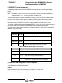
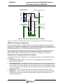
Last Updated: 21-June-2010 TB-060401C Technical Bulletin, Communicating with SICK MAIHAK Ultrasonic Gas Flowmeter Model FLOWSIC600 OMNI FLOW COMPUTERS, INC. 12620 West Airport Boulevard, Suite 100 Sugar Land, Texas 77478 United States of America Phone-281.240.6161 Fax: 281.240.6162 www.omniflow.com 52-0004-0004/Rev C Page 1 of 22 TB-060401C Communicating with SICK MAIHAK Ultrasonic Gas Flowmeter Model FLOWSIC600 NOTE: User Manual Reference – This Technical Bulletin complements the information contained in the OMNI User Manual and OMNICOM help. Table of Contents Scope ............................................................................................................................................3 Abstract .........................................................................................................................................3 FLOWSIC600 Ultrasonic Flowmeter Theory of Operation ............................................................3 OMNI Flow Computer Logic ..........................................................................................................3 Modbus Communication................................................................................................................5 Wiring Installation ..........................................................................................................................5 OMNI Combo Module Terminal Assignments ...........................................................................6 FLOWSIC600 Terminal Assignments .......................................................................................8 FLOWSIC600 UFM Configuration Options Explained...............................................................8 Option 1.................................................................................................................................................8 Option 2.................................................................................................................................................9 Option 3.................................................................................................................................................9 Option 4.................................................................................................................................................9 Forward & Reverse Flow Signals ..............................................................................................9 Forward & Reverse Flow with Dual Pulse Fidelity Checking...................................................10 OMNI Flow Computer Configuration ...........................................................................................11 Miscellaneous Configuration Meter Run Settings ...................................................................11 Meter Run Setup Entries .........................................................................................................13 OMNI Flow Computer Database Addresses & Index Numbers ..................................................13 OMNI Flow Computer User Displays ..........................................................................................18 SV Module Serial Communications Port .................................................................................18 Meter Run Data .......................................................................................................................20 Figures Figure 1. Figure 2. Figure 3. Figure 4. Figure 5. SICK FLOWSIC600 Ultrasonic Gas Flowmeter ............................................................4 Wiring a FLOWSIC600 Ultrasonic Flowmeter.............................................................10 Wiring a FLOWSIC600 Ultrasonic Flowmeter.............................................................11 OMNI Versions 23 and 27 Firmware...........................................................................19 Meter Run OMNI Versions 23 and 27 Firmware .........................................................20 52-0004-0004/Rev C Page 2 of 22 TB-060401C Communicating with SICK MAIHAK Ultrasonic Gas Flowmeter Model FLOWSIC600 Scope Computers, for gas flow metering systems. APPLICATION REVISION 23.74 .20 and above 23.75 All 27.74 .19 and above 27.73 All Abstract The SICK FLOWSIC600 ultrasonic flowmeter determines the linear gas velocity through the meter tube by using multiple acoustic pulse paths. The flowmeter analyzes these paths employing the delta time travel measurement method. The OMNI Flow Computer either totalizes the flowmeter pulse input signal or determines the flowrate from the serial port data received from the flowmeter. This device communicates with OMNI Flow Computers via OMNI’s ‘SV’ process I/O combo module using a proprietary protocol. To use the scaled pulse output of the SICK FLOWSIC600, the flow computer must have at least one ‘A”, ‘B’, or ‘E’ combo module installed. FLOWSIC600 Ultrasonic Flowmeter Theory of Operation SICK’s ultrasonic gas flow-metering technology incorporates multiple pairs of transducers into a smart digital inferential instrumentation device. This device is installed into a gas pipeline system to measure gas flow. Each pair of transducers emits ultrasonic (acoustic) pulses that travel bi-directionally, to and from each transducer in the pair. Up to four pairs of transducers are positioned across the meter so that the path between each transducer has an axial component; i.e., one transducer is upstream relative to the other. Pulses emitted by the downstream transducer are slowed down by the velocity of the gas. With flow, the pulse takes longer to travel to the upstream transducer than with no flow. Pulses emitted by the upstream transducer are aided by the velocity of the gas. With flow, the pulse takes less time to travel to the downstream transducer. Ultrasonic flowmeters, such as the FLOWSIC600, that apply delta time methodology, measure these two travel times to determine both the linear gas velocity and the speed of sound in the gas. The flowmeter can measure velocity for bi-directional (forward/reverse) flow. OMNI Flow Computer Logic The OMNI Flow Computer can determine the actual flow rate from data received either serially from the FLOWSIC600 Flowmeter (Figure 1), or from a live pulse frequency signal input if one has been connected, assigned, and configured. In this application, Modbus serial communication can be configured as the primary measurement source with the pulse frequency configured as the backup measurement source or vice versa to determine the actual flow rate. The OMNI flow computer can also be configured to use only the Modbus serial communication link with no pulse frequency input. When Modbus communications are available, the flow computer transmits flowing temperature and pressure to the flowmeter to enable it to correct spool dimensions. The OMNI retrieves the accumulated volume from the flowmeter. The flow computer obtains a calculated volume increment by subtracting the new accumulated volume from the previous accumulated volume it retrieved. The flowmeter updates its totalizers on a regular interval depending upon flowing conditions and configuration settings. Updating the OMNI totalizers on this same period would result in somewhat erratic totalizers and sampler pulse outputs, which could upset other equipment connected to the flow computer. The OMNI provides a smooth totalizer update by monitoring the time interval between Flowsic totalizer updates, and distributing the volume increment over a matching time-period. 52-0004-0004/Rev C Page 3 of 22 TB-060401C Communicating with SICK MAIHAK Ultrasonic Gas Flowmeter Model FLOWSIC600 Figure 1. SICK FLOWSIC600 Ultrasonic Gas Flowmeter 52-0004-0004/Rev C Page 4 of 22 TB-060401C Communicating with SICK MAIHAK Ultrasonic Gas Flowmeter Model FLOWSIC600 *NOTE: Totals will be applied in the Reverse or Forwarded direction depending on status of the digital channel configured for flow direction. If a flow direction digital channel is not configured, the flow will be applied in the direction specified in the OMNI configuration for each meter run. In the event of a communication failure between the two devices, the OMNI will not receive serial data. However, the FLOWSIC600 may be fully operational and continue to accumulate volume. In this case, if a pulse signal is available from the flowmeter and the OMNI flow computer is configured to receive the flow pulse signal as a backup, the flow computer will automatically continue to accumulate flow based on this flow pulse train. When normal communications resume, the flow computer will validate and adjust its internal totalizers if necessary to match the Flowsic internal totalizer. The flow computer automatically adjusts its totalizers to account for the small amount of flow that takes place before it detects that a communication failure has occurred (i.e., the OMNI does not immediately start totalizing using the Flowsic pulse train). If a pulse signal from the Flowsic is not available (i.e., not assigned) and the communication link fails, the flow computer immediately stops totalizing. Once communication is reestablished, the OMNI will adjust its internal totalizers to match the accumulated flow in the Flowsic since the last time it was able to read from the Flowsic. In this case, the OMNI may have to add a significant amount of flow to its totalizers, depending upon how much time the communication link was inoperative. In some instances, adjusting the flow computer’s totalizers may not be desirable (e.g., if a flowmeter has been disconnected for a long period of time, or the Flowsic electronics package has been replaced). For these cases, there are flow computer configuration settings that specify the maximum time that a Flowsic serial communication failure can exist, and still be compensated for by adjusting the flow computer totalizers. By default, this maximum time is 15 minutes. Modbus Communication The FLOWSIC600 connects to an external system using the Modbus ASCII protocol via a serial line. This connection is a 2-wire RS-485 serial link. Communications parameters are fixed in the OMNI (Table 1). Table 1. OMNI Flow Computer Fixed Communications Parameters Setting Value Baud Rate 9600 Data Bits 8 Stop Bits 1 Parity None Protocol Modbus ASCII Wiring Installation NOTE: Serial Data Communications – The serial interface between these devices is 2-wire RS-485 mode utilizing a Modbus ASCII protocol. Setting Up and Wiring to OMNI Combo Modules – In order to communicate with SICK FLOWSIC600 ultrasonic flowmeters, the OMNI Flow Computer must be equipped with at least one SV combo module (68-6203). For instructions on jumper setting and other process I/O combination module setup information, please refer to Volume 1, Chapter 2 of the OMNI User Manual. Getting SICK MAIHAK Technical Support – SICK MAIHAK Technical Support is available in Germany or the U.S. Contact and technical information is available at website: www.sickmaihak.com There are several options for wiring a SICK FLOWSIC600 ultrasonic meter to an OMNI flow computer. The option to implement depends upon requirements of the flow metering system. Contact SICK MAIHAK Technical Support (see sidebar) for assistance with software/hardware configuration of the flowmeter. 52-0004-0004/Rev C Page 5 of 22 TB-060401C Communicating with SICK MAIHAK Ultrasonic Gas Flowmeter Model FLOWSIC600 Always interconnect these devices via a 2-wire RS-485 serial interface from the FLOWSIC600 to an OMNI SV combo module serial port. The OMNI uses the Modbus ASCII protocol to determine the incremental flow from the data it retrieves from the FLOWSIC600 accumulators. The OMNI also transmits the fluid temperature and pressure to the flowmeter to allow the flowmeter to correct for dimensional changes of the measurement spool. In addition to serial data, the OMNI can also receive live forward and/or reverse flow pulse signals from the FLOWSIC600. The Flowsic transmits pulse frequencies through wires typically connected to an OMNI combo module. Connecting two FLOWSIC600 pulse output channels to the OMNI can provide pulse fidelity and integrity checking. To perform pulse fidelity and integrity checking, the OMNI must have an E combo module installed. OMNI Combo Module Terminal Assignments The OMNI requires the SV combo module for serial communications plus either an A or a B combo module if also connecting the flow pulse signal(s) (Requires an E combo module instead of the A or B combo module if utilizing the Pulse Fidelity and Integrity Checking feature with dual pulse trains). Tables 2 thru 5 specify the terminal assignments for each module type when connecting wires to the OMNI. The terminal block number (TBn) on the OMNI back panel for each combo module corresponds to the slot on the motherboard into which the module is plugged. NOTE: The bolded areas indicate pinouts applicable to interfacing the OMNI to the SICK FLOWSIC600 flowmeter. Table 2. OMNI SV Combo Module Back Panel Terminal Assignments (TBn) Terminal 1 Port # 1 (3): RS-485 B Wire 2 Port # 1 (3): RS-485 A Wire 3 Port # 2 (4): RS-485 B Wire 4 Port # 2 (4): RS+485 A Wire 5 Signal Return for 4-20mA Analog Outputs 6 Signal Return for 4-20mA Analog Outputs 7 Analog Output # 5: 4-20mA 8 Analog Output # 6: 4-20mA 9 Analog Output # 3: 4-20mA 10 Analog Output # 4: 4-20mA 11 Analog Output # 1: 4-20mA 12 Analog Output # 2: 4-20mA None: 52-0004-0004/Rev C Signal Description Numbers in parenthesis “( )” refer to SV module 2 if installed. Page 6 of 22 TB-060401C Communicating with SICK MAIHAK Ultrasonic Gas Flowmeter Model FLOWSIC600 Table 3. OMNI E Combo Module Back Panel Terminal Assignments (TBn) Terminal Signal Description 1 2 3 4 Input Channel # 1: 1-5v, 4-20mA, RTD Input Channel # 1: Isolated Signal Return Input Channel # 2: 1-5v, 4-20mA, RTD Input Channel # 2: Isolated Signal Return 5 Input Channel # 3: Flowmeter Pulses (independent channel or Pulse Train A for Pulse Fidelity) 6 Input Channel # 4: Flowmeter Pulses (independent channel or Pulse Train B for Pulse Fidelity) 7 8 9 Double Chronometry Detector Switch Input (Active Low) RTD Excitation Current Source Output #2 RTD Excitation Current Source Output #1 10 Signal Return for Terminals 5, 6, 7, 8, 9, 11, & 12 (Internally connected to DC power return) 11 12 Analog Output # 1: 4-20mA Analog Output # 2: 4-20mA Table 4. OMNI A Combo Module Back Panel Terminal Assignments (TBn) Terminal Signal Description 1 2 3 4 Input Channel # 1: 1-5v, 4-20mA, RTD Input Channel # 1: Isolated Signal Return Input Channel # 2: 1-5v, 4-20mA, RTD Input Channel # 2: Isolated Signal Return 5 Input Channel # 3: Flowmeter Pulses 6 Input Channel # 3: Isolated Signal Return 7 Input Channel # 4” Flowmeter Pulses 8 Input Channel # 4: Isolated Signal Return 9 RTD Excitation Current Source Output #1 Signal Return for Terminals 9, 11 & 12 (Internally connected to DC power return Analog Output # 1: 4-20mA Analog Output # 2: 4-20mA or RTD Excitation Current Source Output #2 (See JP12 Setting) 10 11 12 Table 5. OMNI B Combo Module Back Panel Terminal Assignments (TBn) Terminal 1 2 3 4 Input Channel # 1: 1-5v, 4-20mA, RTD Input Channel # 1: Isolated Signal Return Input Channel # 2: 1-5v, 4-20mA, RTD Input Channel # 2: Isolated Signal Return 5 Input Channel # 3: Flowmeter Pulses 6 Input Channel # 3: Isolated Signal Return 7 8 9 Input Channel # 4: Densitometer Pulses Input Channel # 4: Isolated Signal Return RTD Excitation Current Source Output #1 Signal Return for Terminals 9, 11 & 12 (Internally connected to DC power return Analog Output # 1: 4-20mA RTD Excitation Current Source Output #2 (See JP12 Setting) 10 11 12 52-0004-0004/Rev C Signal Description Page 7 of 22 TB-060401C Communicating with SICK MAIHAK Ultrasonic Gas Flowmeter Model FLOWSIC600 FLOWSIC600 Terminal Assignments There are two hardware variants of the FLOWSIC600 flowmeter that can be selected using hardware jumper settings. Consult the Flowsic manual for specific details on procedures to change the related jumpers. NOTE: The hardware “variant” is not the same as the hardware “version”referenced in the sidebar on page 1 of this bulletin (i.e., both hardware “versions” 1.0 and 2.0 have user selectable Hardware “variant” 1 or 2. Variant 2 provides a second serial port. The hardware variant can be selected via the Jumper 2 setting on what is known as the Back Board on the flowmeter. In addition to selecting the hardware variant, the same jumper can be used to specify if the outputs are to be Open Collector (Active) or NAMUR (Passive) signals. Use the Open Collector option when connecting to the OMNI Flow Computer. DC Coupling selected on the A and E combo module and if using the NAMUR input, select AC coupling jumper on the A and E combo module. The “variant” or specific assignments of the digital outputs DO 1 through DO 3 can be software configured with the help of the MEPAFLOW 600 PC-Based program used to configure the flowmeter. The bolded areas in Tables 6 and 7 indicate how the flowmeter should be configured for interfacing to the OMNI when using either variant. Table 6. Hardware Variant 1 (without current output) Output Terminal Assignment Digital Out 0 31+, 32- Actual Volume (frequency signal), inverted to Digital Output 1, constant “open” with fault Serial Interface 33+, 34- RS-485 2-Wire Digital Out 1 51+, 52- Actual Volume (frequency signal) Digital Out 2 41+, 42- Data Invalid or Config Mode = High signal Data Valid or Measurement Mode = Low signal Digital Out 3 81+, 82- Direction of Flow Forward Flow = High signal, Reverse Flow = Low signal Table 7. Hardware Variant 2 (with current output) Output Terminal Assignment Digital Out 0 31+, 32- Actual Volume (frequency signal Serial Interface 33+, 34- RS-485 2-Wire Port 1 Digital Out 1 51+, 52- Actual Volume (frequency signal) Digital Out 2 Or Serial Interface 41+, 42- Data Invalid = High signal (Config Mode) and Data Valid = Low signal (Measurement Mode) RS-485 2-Wire Port 2 Digital Out 3 81+, 82- Direction of Flow Forward Flow = High signal, Reverse Flow = Low signal FLOWSIC600 UFM Configuration Options Explained Following are the software and hardware settings available in the SICK MAIHAK FLOWSIC600 UFM when connecting to the OMNI Flow Computer. Option 1 Frequency outputs D0, D1 (51/52-31/32) setting = Flow (DO1) + Direction (DO0) Either Normally Open (D0+D1) or Normally Closed (D0+D1) Hardware jumper set to DO0 = frequency 52-0004-0004/Rev C Page 8 of 22 TB-060401C Communicating with SICK MAIHAK Ultrasonic Gas Flowmeter Model FLOWSIC600 This configuration creates the same frequency on terminals 31/32 and 51/52 but the phase shift is dependent on flow direction. Dual pulse trains are provided simultaneously in both the forward and reverse flow directions for pulse fidelity and integrity checking. The phase shift in the forward direction is 90 degrees and 180 degrees in the reverse direction. It is possible to use this configuration with the OMNI flow computer if configuring two separate meter runs in the flow computer with each meter run representing different flow directions, and with each meter run assigned different flow pulse input channels. Option 2 Frequency output D0, D1 (51/52-31/32) setting = Flow (DO1) + Invalid (DO0) Either Normally Open (D0+D1) or Normally Closed (D0+D1) Hardware jumper set to DO0 = frequency This configuration provides dual pulse trains for purposes of dual pulse fidelity and integrity checking with the signals 180 degrees out of phase. Both signals are normally active simultaneously in either the forward or reverse flow directions. If there exists a data invalid situation in the flowmeter, terminals 31/32 will not output a frequency. NOTE: An internal Data Invalid situation or switching the meter to "Configuration" mode will cause a Data Invalid signal to be output. Option 3 Frequency output D0, D1 (31/32-51/52) setting = Flow FW(DO1) + RW(DO0) Either Normally Open (D0+D1) or Normally Closed (D0+D1) Hardware jumper set to DO0 = frequency This configuration also provides dual pulse trains but not for pulse fidelity and integrity checking. The signals are mutually exclusive of one another - while one signal is on, the other is off. The DO1 signal is used to indicate forward flow and the DO0 signal is used to indicate reverse flow. Dependent on the flow direction, the meter outputs a frequency only on terminals 51/52 for forward flow or the meter outputs a frequency only on terminals 31/32 for reverse flow. Option 4 Frequency output D0, D1 (31/32-51/52) setting = Flow FW (DO1) + status output (DO0) Either Normally Open (D0+D1) or Normally Closed (D0+D1) Hardware jumper set to DO0 = frequency This configuration provides only one pulse train on terminals 51/52. Terminals 31/32 can be configured for status output signals (i.e. Data Invalid, Warning, Flow Direction, and Check Request). Forward & Reverse Flow Signals Figure 2 is a typical wiring installation between the SICK FLOWSIC600 and an OMNI 6000 for serial data and both forward and reverse flow signals, without pulse fidelity and Integrity checking. In this example, assume that the OMNI 6000 has an A or B Combo module plugged into slot TB5, and an SV module in slot TB6. 52-0004-0004/Rev C Page 9 of 22 TB-060401C Communicating with SICK MAIHAK Ultrasonic Gas Flowmeter Model FLOWSIC600 SICK Flowsic 600 Field Connection Terminal OMNI A Combo Module Terminals (TB5) Freq B+ 31 1 Freq B- 32 2 RS485 + 33 RS485 - 34 Freq A+ Freq A- 3 Pulse In 51 Return 52 Mode+ 41 Pulse In Return 4 5 6 7 Mode- 42 Flow Dir+ 81 8 9 Flow Dir- 82 10 3rd Input Channel of A or B Combo OR 4th Input Channel of A Combo 11 12 OMNI Digital I/O Module Terminals (TB1) 1 Digital In 1 2 Digital In 2 OMNI SV Combo Module Terminals (TB6) 1 RS-485 - (B) 2 RS-485 +(A) 3 3 RS-485 - (B) 4 4 RS-485 +(A) 5 5 6 7 All Pull-up Resistors Approximately 2KOhm 8 12 Port #2 ** 6 7 8 9 10 11 Port #1 ** 9 + + + + - - - - OMNI TB11 (- signal internally tied to pin 10 of Combo modules) 10 11 12 Figure 2. Wiring a FLOWSIC600 Ultrasonic Flowmeter *Ports 1 or 2 of the SV1 combo module or ports 3 or 4 of the SV2 combo module can be utilized. Forward & Reverse Flow with Dual Pulse Fidelity Checking Figure 3 is a typical wiring installation between the SICK FLOWSIC600 and an OMNI 6000 for serial data and forward and/or reverse flow signals, with connections for pulse fidelity and integrity checking. In this example, assume that the OMNI 6000 has an E module plugged into slot TB5, and an SV module in slot TB6. 52-0004-0004/Rev C Page 10 of 22 TB-060401C Communicating with SICK MAIHAK Ultrasonic Gas Flowmeter Model FLOWSIC600 SICK Flowsic 600 Field Connection Terminal Freq B- 31 32 RS485 + 33 RS485 - 34 Freq B+ Freq A+ Freq A- 51 52 Mode+ 41 Mode- 42 Flow Dir+ 81 Flow Dir- 82 OMNI E Combo Module Terminals (TB5) 1 2 3 Pulse A+ In Pulse B+ In 4 5 3rd Input Channel 6 4th Input Channel 7 8 Return 9 10 11 12 OMNI Digital I/O Module Terminals (TB1) 1 Digital In 1 2 Digital In 2 OMNI SV Combo Module Terminals (TB6) 1 RS-485 - (B) 2 RS-485 +(A) 3 3 RS-485 - (B) 4 5 4 RS-485 +(A) 5 6 All Resistors Approximately 2KOhm 7 8 9 10 11 12 Port #1 ** Port #2 ** 6 7 8 9 + + + + - - - - OMNI TB11 (- signal internally tied to pin 10 of Combo modules) 10 11 12 Figure 3. Wiring a FLOWSIC600 Ultrasonic Flowmeter **Ports 1 or 2 of the SV1 Combo module or ports 3 or 4 of the SV2 Combo module can be utilized. OMNI Flow Computer Configuration Use either the flow computer’s front panel keypad or the OmniCom for Windows PC-based software program to enter configuration settings unique to the SICK FLOWSIC600 flowmeter. The configuration settings that are specific to the FLOWSIC600 are under Miscellaneous Setup, Configure Meter Run menu and the Meter Run Setup menu if accessing the settings from the keypad. Enter the miscellaneous configuration meter run settings first and then proceed to the meter run setup entries (Chapter 2 ‘Flow Computer Configuration’ in Volume 3 of the OMNI User Manual, and the Technical Bulletin 960701 (52-0000-0001) ‘Overview of OmniCom Configuration PC Software. Miscellaneous Configuration Meter Run Settings The following miscellaneous configuration meter run settings correspond to the FLOWSIC600 ultrasonic gas flowmeter: Select Flowmeter Device Type – For each meter run, enter [10] to select the SICK Ultrasonic flowmeter as the device type. Select SV Module Port – The OMNI Flow Computer can accept two SV combo modules (these are not the same as regular serial modules). With one SV module, two SV ports are available, and with two SV modules, four ports are available. For each ultrasonic meter run, enter the SV port number (1 to 4) to which the SV module’s RS-485 2-wire serial interface input from the FLOWSIC600 flowmeter is wired to the OMNI. SICK Address – This is the address ID of the SICK ultrasonic flowmeter communications port. SICK Retry # – This is the number of SV serial port communications consecutive retries the OMNI will attempt with the flowmeter when the flowmeter does not respond before the OMNI raises a communications fail alarm. 52-0004-0004/Rev C Page 11 of 22 TB-060401C Communicating with SICK MAIHAK Ultrasonic Gas Flowmeter Model FLOWSIC600 Delay Seconds – This is the number of seconds the OMNI should wait for a response from the flowmeter before the OMNI attempts a communications retry. The flowmeter response time can vary depending on the tasks being performed at the time data is requested. If the specified number of retries has been exhausted without a response from the flowmeter, the flow computer will raise a communications failure alarm. (Recommended value is 2 seconds) Flow I/O Point – Enter the flow pulse input channel number of the flow computer where the ultrasonic flowmeter pulse signal is wired to. Assign flowmeter pulse signals only to Input Channels #3 and #4 of A or E combo modules, or input channel #3 of a B combo module. Dual Pulse? (Y/N) – A “Y” indicates to the flow computer there are two pulse trains coming from the flowmeter and they should be compared using the Pulse Fidelity and Integrity Checking feature. The channel assigned in the previous setting will be considered the “A” pulse train and the channel immediately following will be considered the “B” pulse train. Ensure the pulse train signals are wired accordingly. NOTE: Use of this feature requires an E-Combo module. Select Flow Direction (F/R) – FLOWSIC600 flowmeters allow for bi-directional flow measurement. Set up the flow computer to totalize either the forward or the reverse flow on any meter run with an ultrasonic flowmeter. NOTE: If you would like the OMNI flow computer to measure flow in both directions, you should set up two meter runs in the OMNI, one configured for forward flow and the other configured for reverse flow. Flow Direction Digital Input # – Specify which digital input channel in the OMNI will be receiving the signal indicative of the flow direction. This input signal is used for purposes of flow pulses totalizing only and not for totalizing with respect to the serial port data. The OMNI will use this status signal if there is a failover from the serial communications link to the pulses OR if the pulses are specified as the primary means of measurement. A high output digital signal from the flowmeter indicates the flow is in the forward direction whereas a low signal indicates the flow is in the reverse direction. If the signal indicates a direction that is different than what is configured for the Select Flow Direction setting, the OMNI will not totalize flow for the respective meter run and will set flag 2n67 to indicate a flow direction mismatch. Measurement Status Digital Input # – This input signal is used for purposes of flow pulses totalizing only and not for totalizing with respect to the serial port data. The OMNI will use this status signal if there is a failover from the serial communications link to the pulses OR if the pulses are specified as the primary means of measurement. A high output digital signal from the flowmeter indicates the flowmeter is in the “configuration” mode whereas a low signal indicates the flowmeter is in the “measurement” mode. Specify which digital input channel in the OMNI will be receiving the signal indicative of the measurement status. NOTE: When the flowmeter indicates it is in the configuration mode, the OMNI will not totalize. Primary Flow – This setting instructs the OMNI flow computer to use either the pulse input channel or the SV serial communications data as the primary means of calculating flow. Options are: 0 = Select Serial Data as primary flow. This means that the SV serial communications data will be the primary and the pulse input channel, if assigned, will be used as a backup means of flow calculations by the flow computer. 1 = Select Pulse Input as primary flow. This means that the flow pulses received from the flowmeter will be the primary and the SV serial communications data will be used as a backup means of flow calculations by the flow computer. 52-0004-0004/Rev C Page 12 of 22 TB-060401C Communicating with SICK MAIHAK Ultrasonic Gas Flowmeter Model FLOWSIC600 Meter Run Setup Entries The following meter run setup entries in the OMNI Flow Computer are available for the FLOWSIC600 ultrasonic flowmeter: Velocity of Sound (VOS) Deviation Percent from Average – In instances where the serial data is being used as the means of totalizing, the flow computer can verify that the average VOS calculated for all paths conforms to the VOS of each individual path. This entry is the maximum percent that any one path VOS varies from the average VOS of all the paths. The flow computer will raise an alarm if this percentage limit is exceeded. AGA 10 Velocity of Sound (VOS) Deviation Percent from Average – Only valid if AGA 10 is enabled in the OMNI flow computer. The flow computer can verify that the average VOS calculated for all FLOWSIC600 paths conforms to the AGA 10 VOS calculated by the OMNI flow computer. The flow computer will raise an alarm if this percentage limit is exceeded. Flow Minutes – Only valid if a flow pulses I/O point is assigned. The time interval can be set for comparing the flow pulses input flow with the SV communications serial link flow. If the flow deviation exceeds the Flow Deviation Percent setting (see next setting) when this comparison is made, the OMNI will switch from the primary (flow pulses) to the backup source (SV serial link) for calculating flow. NOTE: It is recommended a minimum of 60 minutes be specified for this setting due to the fluctuating flow pulse frequency.) Maximum Flow Deviation Percent Only valid if a flow pulses I/O point is assigned - this is the allowable percent of deviation between the calculated flow from the pulse input channel compared to the FLOWSIC600 flow data received via the OMNI SV serial port. The OMNI raises the pulse suspect alarm if the flow deviation percentage exceeds this limit and switches to the SV serial port as the primary means of totalizing. NOTE: See the previous setting relating to Flow Minutes. Maximum Meter Downtime Enter the maximum allowable flowmeter downtime in minutes. If communication downtime between the OMNI and the FLOWSIC600 is greater than this value, the OMNI will not adjust its internal totalizers to match the FLOWSIC600 totalizer increment when serial communications is reestablished. Depending upon how much time the communication link and pulses were inoperative and the amount of flow that occurred during this downtime, when communications is reestablished within the time specified in this setting, the OMNI may have to add a significant amount of flow to its totalizers. (Default = 15 minutes). NOTE: If you do not wish the OMNI to compensate for any flowmeter downtime, specify a value of 0 for this setting. OMNI Flow Computer Database Addresses & Index Numbers Tables 8 thru 14 list the Modbus database addresses assigned within OMNI firmware to the FLOWSIC600 ultrasonic metering feature. These tables categorize data type. 52-0004-0004/Rev C Page 13 of 22 TB-060401C Communicating with SICK MAIHAK Ultrasonic Gas Flowmeter Model FLOWSIC600 Table 8. Meter Run Alarm Status Points – Real Time Dates Database Address for Meter Run Number Description Loss of communication Alarm Pulse Suspect Alarm Flow rate deviation Alarm Meter in Configuration mode Meter in Reduced Accuracy mode Path 1 Error Path 2 Error Path 3 Error Path 4 Error SICK EPROM Error I/O Parameter Error Warn I/O Range DSP – fault Flow Direction Mismatch DSP Parameter Error Path 1 AGC Deviation Alarm Path 2 AGC Deviation Alarm Path 3 AGC Deviation Alarm Path 4 AGC Deviation Alarm Path 1 SOS Deviation Warning Path 2 SOS Deviation Warning Path 3 SOS Deviation Warning Path 4 SOS Deviation Warning Path 1 - VOS Deviation Alarm Path 2 - VOS Deviation Alarm Path 3 - VOS Deviation Alarm Path 3 SOS Deviation Warning 52-0004-0004/Rev C 1 2 3 4 2154 2155 2156 2157 2158 2254 2255 2256 2257 2258 2354 2355 2356 2357 2358 2454 2455 2456 2457 2458 2159 2160 2161 2162 2163 2164 2165 2166 2167 2168 2169 2170 2171 2172 2173 2174 2175 2176 2181 2182 2183 2175 2259 2260 2261 2262 2263 2264 2265 2266 2267 2268 2269 2270 2271 2272 2273 2274 2275 2276 2281 2282 2283 2275 2359 2360 2361 2362 2363 2364 2365 2366 2367 2368 2369 2370 2371 2372 2373 2374 2375 2376 2381 2382 2383 2375 2459 2460 2461 2462 2463 2464 2465 2466 2467 2468 2469 2470 2471 2472 2473 2474 2475 2476 2481 2482 2483 2475 Page 14 of 22 TB-060401C Communicating with SICK MAIHAK Ultrasonic Gas Flowmeter Model FLOWSIC600 Table 9. 16-Bit Integer Registers – Real Time Data Description Database Address for Meter Run Number 1 Flow Direction Configuration 2 3 4 3155 3255 3355 3455 3171 3172 3173 3174 3175 3176 3177 3178 3180 3181 3182 3183 3184 3185 3186 3187 3188 3189 3271 3272 3273 3274 3275 3276 3277 3278 3280 3281 3282 3283 3284 3285 3286 3287 3288 3289 3471 3472 3473 3474 3475 3476 3477 3478 3480 3481 3482 3483 3484 3485 3486 3487 3488 3489 (0=forward,1=reverse) System Control Register System Status Numbers of Paths Flow Meter Type Valid Samples Path 1 Valid Samples Path 2 Valid Samples Path 3 Valid Samples Path 4 AGC Level Receiver 1A AGC Level Receiver 1B AGC Level Receiver 2A AGC Level Receiver 2B AGC Level Receiver 3A AGC Level Receiver 3B AGC Level Receiver 4A AGC Level Receiver 4B VBatt Level Frequency Current 3371 3372 3373 3374 3375 3376 3377 3378 3380 3381 3382 3383 3384 3385 3386 3387 3388 3389 Table 10. 32-Bit Integer Register – Real Time Data Description Flowsic SN Device Flowsic Software Version Flowsic SN Analog Flowsic Constants CRC Flowsic Program CRC Flowsic Parameter CRC Flowsic Forward Volume Flowsic Fwd Volume Error Flowsic Reverse Volume Flowsic Rev Volume Error Flowsic Counter Resolution Flowsic Response Delay 52-0004-0004/Rev C Database Address for Meter Run Number 1 2 3 4 15524 15525 15526 15527 15528 15529 15530 15531 15532 15533 15534 15535 15624 15625 15626 15627 15628 15629 15630 15631 15632 15633 15634 15635 15724 15725 15726 15727 15728 15729 15730 15731 15732 15733 15734 15735 15824 15825 15826 15827 15828 15829 15830 15831 15832 15833 15834 15835 Page 15 of 22 TB-060401C Communicating with SICK MAIHAK Ultrasonic Gas Flowmeter Model FLOWSIC600 Table 11. 32-Bit IEEE Floating Points – Real Time Data Database Address Description Database Address for Meter Run Number 1 2 3 Description 4 for Meter Run Number 1 2 3 4 17141 17151 17161 17171 Path 1 Velocity of Sound 17527 17627 17727 17827 17142 17152 17162 17172 Path 2 Velocity of Sound 17528 17628 17728 17828 17143 17153 17163 17173 Path 3 Velocity of Sound 17513 17613 17713 17813 Path 4 Velocity of Sound 17213 17217 17221 17225 Path 1 Gas Velocity 17529 17629 17729 17829 17530 17630 17730 17830 17533 17633 17733 17833 17214 17218 17222 17226 Path 2 Gas Velocity 17534 17634 17734 17834 17215 17216 17516 17521 17522 17535 17536 17525 17526 17518 Serial Gross flow during Flow Minutes period Pulses Gross flow during Flow Minutes period Calculated Flow Dev % Max flow dev (%) allowed Total increment from serial link nd (2 to last read) Total increment from serial link (last read) Total from pulse input Dev % between serial & pulse *Max VOS dev (%) allowed Avg VOS – All Paths Avg Gas Velocity – All Paths SICK Press – Absolute BarA 17523 SICK Temperature - Kelvin 17524 SICK K-Factor 17538 Temperature Pressure 7105 7106 17219 17220 17616 17621 17622 17223 17224 17716 17721 17722 17227 17228 17816 17821 17822 Path 3 Gas Velocity Path 4 Gas Velocity Volume Flowrate – Line Volume Flowrate - Base **Max Allowed VOS Dev % (OMNI v23 firmware) 17623 17723 17823 **Max Allowed VOS Dev % (OMNI v27 firmware) 17624 17724 17824 ***OMNI Calculated AGA10 VOS in m/s (OMNI v23 & 27 firmware) 17638 17738 17838 ***OMNI Calculated AGA10 VOS in ft/s (OMNI v23 & 27 firmware) 7205 7305 7405 7206 7306 7406 17635 17636 17625 17626 17618 17735 17736 17725 17726 17718 17835 17836 17825 17826 17818 17599 17699 17799 17899 18524 18624 18724 18824 18532 18632 18732 18832 * The VOS of each individual path is compared against the composite VOS in the SICK FLOWSIC600 and an alarm is raised by the OMNI if this percentage limit is exceeded. ** Applicable only if AGA 10 is enabled in the OMNI. This is the result of the comparison between the SICK FLOWSIC600 composite VOS versus the OMNI calculated AGA 10 VOS. The OMNI raises an alarm if this percentage limit is exceeded. *** Applicable only if AGA 10 is enabled in the OMNI. 52-0004-0004/Rev C Page 16 of 22 TB-060401C Communicating with SICK MAIHAK Ultrasonic Gas Flowmeter Model FLOWSIC600 Table 12. 32-Bit IEEE Floating Pints Previous Hour’s Average Data 32-Bit IEEEE Floating Points Previous Day’s Average Data 32-bit IEEE Floating Points Previous Hour’s Average Data Description Valid Sample Path 1 Valid Sample Path 2 Valid Sample Path 3 Valid Sample Path 4 AGC Level Receiver 1A AGC Level Receiver 1B AGC Level Receiver 2A AGC Level Receiver 2B AGC Level Receiver 3A AGC Level Receiver 3B AGC Level Receiver 4A AGC Level Receiver 4B Path 1 Gas velocity Path 2 Gas velocity Path 3 Gas velocity Path 4 Gas velocity Path 1 Velocity of Sound Path 2 Velocity of Sound Path 3 Velocity of Sound Path 4 Velocity of Sound 32-bit IEEE Floating Points Previous Day’s Average Data Database Address for Meter Run Number 1 2 3 4 17539 17540 17541 17542 17543 17544 17545 17546 17547 17548 17549 17550 17553 17554 17555 17556 17561 17639 17640 17641 17642 17643 17644 17645 17646 17647 17648 17649 17650 17653 17654 17655 17656 17661 17739 17740 17741 17742 17743 17744 17745 17746 17747 17748 17749 17750 17753 17754 17755 17756 17761 17839 17840 17841 17842 17843 17844 17845 17846 17847 17848 17849 17850 17853 17854 17855 17856 17861 Database Address for Meter Run Number Description 1 2 3 4 17569 17570 17571 17572 17574 17575 17576 17577 17578 17579 17580 17581 17584 17585 17586 17587 17592 17669 17670 17671 17672 17674 17675 17676 17677 17678 17679 17680 17681 17684 17685 17686 17687 17692 17769 17770 17771 17772 17774 17775 17776 17777 17778 17779 17780 17781 17784 17785 17786 17787 17792 17869 17870 17871 17872 17874 17875 17876 17877 17878 17879 17880 17881 17884 17885 17886 17887 17892 17562 17662 17762 17862 Path 2 Velocity of Sound 17593 17693 17793 17893 17563 17663 17763 17863 Path 3 Velocity of Sound 17594 17694 17794 17894 17564 17664 17764 17864 Path 4 Velocity of Sound 17595 17695 17795 17895 Valid Sample Path 1 Valid Sample Path 2 Valid Sample Path 3 Valid Sample Path 4 AGC Level Receiver 1A AGC Level Receiver 1B AGC Level Receiver 2A AGC Level Receiver 2B AGC Level Receiver 3A AGC Level Receiver 3B AGC Level Receiver 4A AGC Level Receiver 4B Path 1 Gas velocity Path 2 Gas velocity Path 3 Gas velocity Path 4 Gas velocity Path 1 Velocity of Sound Table 13. Flow Computer Configuration Data – Miscellaneous Meter Run Configuration Description Database Address for Meter Run Number 1 2 3 Description 4 Flow pulse I/O point # 13001 13014 13027 13040 Flow Direction Digital Input # Flowmeter device type 3108 3208 3308 3408 Meter Mode Digital Input # 0=Measurement 1=Config SV module port # assigned 3153 3253 3353 3453 FLOWSIC600 Modbus ID 3154 3254 3354 3454 Delay Retry Seconds 3155 3255 3355 3455 Flow direction Database Address for Meter Run Number 1 2 3162 3262 3362 3462 3 3163 3263 3363 3463 13445 13446 13447 13448 (0=frwd,1=rvrs) SICK Retry # 3156 3256 3356 3456 Primary Flow (0=Serial, 1=Pulses) 3157 3257 3357 3457 52-0004-0004/Rev C 4 Page 17 of 22 TB-060401C Communicating with SICK MAIHAK Ultrasonic Gas Flowmeter Model FLOWSIC600 Table 14. Flow Computer Configuration Data – Meter Run Setup Description Meter maximum downtime (minutes) Database Address for Meter Run Number 1 2 3 4 3116 3216 3316 3416 Description Database Address for Meter Run Number 1 2 3 4 *VOS deviation (%) 17516 17616 17716 17816 **Max Allowed VOS Dev % (OMNI v23 firmware) **Max Allowed VOS Dev % (OMNI v27 firmware) 17518 17618 17718 17818 Flow Compare Interval Time 3135 3235 3335 3435 – (minutes) Serial to Pulses flow compared Maximum flow deviation (%) 17513 17613 17713 17813 K-factor from SICK UFM 17599 17699 17799 17899 17538 17638 17738 17838 * The VOS of each individual path is compared against the composite VOS in the SICK FLOWSIC600 and an alarm is raised by the OMNI if this percentage limit is exceeded. **Applicable only if AGA10 is enabled in the OMNI. This is the result of the comparison between the SICK FLOWSIC600 Composite VOS versus the OMNI calculated AGA10 VOS. The OMNI raises an alarm if this percentage limit is exceeded. OMNI Flow Computer User Displays SV Module Serial Communications Port You can view live data received via RS-485 communications on the flow computer front panel LCD display only if a SV port is used to input the RS-485 interface from the FLOWSIC600 flowmeter. To view this data, press [Setup] [n] [Display] on the OMNI front panel keypad (where “n” equals the SV port number 1 to 4, you want to display), when in the Display Mode. Figure 4 data displays assume that when you have a version 23 firmware OMNI, the FLOWSIC600 flowmeter will be configured for Imperial Units and when you have a version 27 firmware OMNI, the FLOWSIC600 flowmeter will be configured for Metric Units: OMNI Version 23 Firmware SV Portn FLOWSIC600 Meter Type xxx System Reg xxxx SystemStatus xxxx Path1 Status x Path2 Status x Path3 Status x Path4 Status x Path1 Sample x Path2 Sample x Path3 Sample x Path4 Sample x Path 1A AGC xx Path 1B AGC xx Path 2A AGC xx Path 2B AGC xx Path 3A AGC xx Path 3B AGC xx Path 4A AGC xx Path 4B AGC xx VBatt Level xxxxx Freq Current xxxxx SN Device xxx 52-0004-0004/Rev C OMNI Version 27 Firmware SV Portn FLOWSIC600 Meter Type xxx System Reg xxxx SystemStatus xxxxx Path1 Status x Path2 Status x Path3 Status x Path4 Status x Path1 Sample x Path2 Sample x Path3 Sample x Path4 Sample x Path 1A AGC xx Path 1B AGC xx Path 2A AGC xx Path 2B AGC xx Path 3A AGC xx Path 3B AGC xx Path 4A AGC xx Path 4B AGC xx VBatt Level xxxxx Freq Current xxxx SN Device xxx Page 18 of 22 TB-060401C Communicating with SICK MAIHAK Ultrasonic Gas Flowmeter Model FLOWSIC600 SW Version xxxx SN Analog xxx Constants CRC xxxx Program CRC xxxx Parameter CRC xxxx Fwd Vol xxxxxx.x F.VolErr xxxx.x Rev Vol xxx.x R.VolErr .x CtResolution xxx ResponseDely x Continued (version 23) FwRateLn xxxx.xxx FwRateBs .xxx Avg.VOS xxxx.xxxxx Avg Vel xx.xxxxx VOS P1 xxxx.xxxxx VOS P2 xxx.xxxxx VOS P3 xxx.xxxxx VOS P4 xx.xxxxx Vel P1 xx.xxxxx Vel P2 xx.xxxxx Vel P3 xx.xxxxx Vel P4 xx.xxxxx SNR 1A xx.xxx SNR 1B xx.xxx SNR 2A xx.xxx SNR 2B xx.xxx SNR 3A xx.xxx SNR 3B xx.xxx SNR 4A xx.xxx SNR 4B xx.xxx Temp K xxx.xx P. (abs) xxx.xxx RealGasFcx .xxxxxx Temp Base K xxx.xxx P.Base xx.xxxxx RealFcBas x.xxxxxx MFp/unit xxx.xxx LowCutOff xx.xxx AdjFcFwd x.xxxxxx AdjFcRev x.xxxxxx ZeroOffset .xxxx Temp Fix xxx.xxx PressureFix xx.xxx CompressFix x.xxxx SW Version xxxx SN Analog xxx Constants CRC xxxx Program CRC xxxx Parameter CRC xxxx Fwd Vol xxxxx.x F.VolErr xxxx.x Rev Vol xxx.x R.VolErr .x CtResolution xxx ResponseDely x Continued (version 27) FwRateLn xxxx.xxx FwRateBs .xxx Avg.VOS xxxx.xxxxx Avg Vel xx.xxxxx VOS P1 xxxx.xxxxx VOS P2 xxxx.xxxxx VOS P3 xxxx.xxxxx VOS P4 xxxx.xxxxx Vel P1 xx.xxxxx Vel P2 xx.xxxxx Vel P3 xx.xxxxx Vel P4 xx.xxxxx SNR 1A xx.xxx SNR 1B xx.xxx SNR 2A xx.xxx SNR 2B xx.xxx SNR 3A xx.xxx SNR 3B xx.xxx SNR 4A xx.xxx SNR 4B xx.xxx Temp K xxx.xx P. (abs) xxx.xxx RealGasFc x.xxxxxx Temp Base K xxx.xxx P.Base xx.xxxxx RealFcBas x.xxxxxx MFp/unit xxx.xxx LowCutOff xx.xxx AdjFcFwd x.xxxxxx AdjFcRev x.xxxxxx ZeroOffset .xxxx Temp Fix xx.xxx PressureFix xx.xxx CompressFix x.xxxx Figure 4. OMNI Versions 23 and 27 Firmware 52-0004-0004/Rev C Page 19 of 22 TB-060401C Communicating with SICK MAIHAK Ultrasonic Gas Flowmeter Model FLOWSIC600 Meter Run Data To view the meter run data on the flow computer LCD display, press [Meter] [n] [Display] on the OMNI front panel keypad (where “n” equals the meter run number, 1 to 4, you want to display), when in the Display Mode. Figure 5 data will display: OMNI Version 23 Firmware METER #n FLOWSIC600 VEL ft/s xx.xxxxx KF P/ft3 xxx.xxx Flowft3h xxxx.xx VOS ft/s xxxx.xxxxx Fwd Vol xxxxxx.x Rev Vol xxx.x P. psia xxx.xx T. Deg.K xxx.xx GasVelP1 xx.xxxxx GasVelP2 xx.xxxxx GasVelP3 xx.xxxxx GasVelP4 xx.xxxxx VOS P1 xxxx.xxxxx VOS P2 xxxx.xxxxx VOS P3 xxxx.xxxxx VOS P4 xxxx.xxxxx OMNI Version 27 Firmware METER #n FLOWSIC600 VEL m/s xx.xxxxx KF P/m3 xxx.xxx FlowM3/h xxxx.xx VOS m/s xx.xxxxx Fwd Vol xxxxxx.x Rev Vol xxx.x P. bara xxx.xx T. Deg.K xxx.xx GasVelP1 xx.xxxxx GasVelP2 xx.xxxxx GasVelP3 xx.xxxxx GasVelP4 xx.xxxxx VOS P1 xxxx.xxxxx VOS P2 xxxx.xxxxx VOS P3 xxxx.xxxxx VOS P4 xxxx.xxxxx Figure 5. Meter Run OMNI Versions 23 and 27 Firmware 52-0004-0004/Rev C Page 20 of 22 TB-060401C Communicating with SICK MAIHAK Ultrasonic Gas Flowmeter Model FLOWSIC600 This page left intentionally blank. 52-0004-0004/Rev C Page 21 of 22 TB-060401C Communicating with SICK MAIHAK Ultrasonic Gas Flowmeter Model FLOWSIC600 DOCUMENT REVISION HISTORY DOCUMENT INITIAL RELEASE DATE..................................................... 21-April-2006 REVISION A B C 52-0004-0004/Rev C DATE 21-April-2006 09-April-2009 21-June-2010 PURPOSE / CHANGE REQUEST Maintained on the web - Initial release DCR 090112 DCR 100080 Page 22 of 22