1
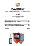
PERSONAL WIRELESS TIMING SYSTEM
CHRONOSPLIT
HL 640
SIMPLIFIED USER MANUAL
Version 5, 04/2008
1.
1. HOW TO USE THE CHRONOSPLIT HL 640 .......................................... Page 2
2.
2. USING THE HL 640-1 TRANSMITTER ................................................... Page 4
3.
3. TECHNICAL SPECIFICATIONS ............................................................. Page 5
4.
4. HL 640-2 USB INTERFACE DRIVER SETUP......................................... Page 6
5.
5. DATA DOWNLOAD SOFTWARE SETUP .............................................. Page 9
6.
6. DATA DOWNLOAD ON PC ..................................................................... Page9
7.
7. SERVICE ............................................................................................... Page 11
1
1. HOW TO USE THE CHRONOSPLIT HL 640
Terminology: "Activate“ refers to pushing and holding the button indicated.
If the ChronoSplit is off (LCD display blank), activate START/STOP and SPLIT/LAP simultaneously with SET
and keep them held for 2 – 3 seconds to turn ON. Use the same method to turn OFF (if not to be used for
long periods). If any abnormal operation is encountered, perform a reset of the ChronoSplit in the same way.
All operating parameters (Time-of-Day set, date, etc.) must be reintroduced when a reset is performed. If the
ChronoSplit will not respond to any button use, open the ChronoSplit and remove and reinsert the battery.
ATTENTION. Make certain you have a real problem with the ChronoSplit before opening the case.
Access to the different timing modes can be seen by using the MODE button. Activate (Hold down) the
MODE button and use the SPLIT/LAP button to scroll through the timing mode options as follows:
TIME
Sets Time of Day. To set, press the SET button until the Hours segment starts to flash. Adjust the hours with
START/STOP (+) or SPLIT/LAP (-). Press SET to confirm the selection and proceed to the same functions
for minutes and seconds. At the exact moment of correct synchronization, press SET again.
DATE
Same as for TIME but affects date setting. Confirm with SET.
AUTO SPLIT
Selects Automatic Timing Mode with SPLIT functions. This mode is driven by remote radio signals from
the transmitters HL 640 - 1 attached to your timing sensors at each timing point (photocells, start gate, etc.. )
(Channel 1 / START - Channel 2 or 3 / INTERMEDIATE - Channel 4 / FINISH - A new timing session is
triggered automatically from any new Channel 1 START signal received by the ChronoSplit. All timing
session must end with a Channel 4 FINISH if you don’t want to be disturbed by other impulses
(intermediates).
AUTO LAP
Selects Automatic Timing Mode with LAP functions. This mode is driven by remote radio signals from the
transmitters HL 640 - 1 attached to your timing sensors at each timing point (photocells, start gate, etc.. )
(Channel 1 / LAP - Channel 2 or 3 / INTERMEDIATE - Channel 4 / FINISH - A new timing session is
triggered by manually activating the SET and START/STOP buttons. (Note: intermediate times are not
shown on the LCD display but they are memorized for download and review later).
MAN SPLIT
Manual stopwatch timing mode in SPLIT that takes all timing signals from the ChronoSplit buttons with no
radio connection to remote sensors. Use START to begin timing, SPLIT to effect Intermediate times, and
STOP to finish. RESTART using START. After a STOP, use (hold down) SPLIT to reset the ChronoSplit to
zero and begin a new session.
MAN LAP
Manual timing mode in LAP that takes all timing signals from the ChronoSplit buttons with no radio
connection to remote sensors. Use START to begin timing, LAP to effect lap timing, STOP to finish. After a
STOP, use LAP to reset the ChronoSplit to zero and begin a new session.
REC AUTO SPLIT or REC MAN SPLIT
Recalls data on the ChronoSplit for viewing any of the recorded timing sessions. FIFO (First-in, First Out)
memory recall. Use START/STOP to recall most recent session times. Use SPLIT/LAP to move to other
timing sessions in memory. The best timing session encountered in the memory of all sessions will feature a
“BEST” in the LCD display. To erase the memory activate SET and START/STOP (the LCD display will
indicate REC -- -- -- --).
REC AUTO LAP ou REC MAN LAP
Recalls data on the ChronoSplit for viewing any or the recorded timing sessions. FIFO (First-in, First Out)
memory recall. Use START/STOP to recall most recent session times. Use LAP to move to other timing
sessions in memory. The best lap of each timing session encountered in the memory or all sessions will
feature a “BEST” in the LCD display. To erase the memory activate SET and START/STOP (the LCD display
will indicate REC -- -- -- --).
2
ID
Identification number that can be assigned to each ChronoSplit, or the bib number of the racer being timed.
(from 0001 to 9999). This allows you to track data from each ChronoSplit using separate ID numbers and to
discern between different data sets from multiple ChronoSplit within a group of athletes. To input a new ID
number activates SET until the leftmost digit begins to flash. Input the new number with START/STOP (+) or
SPLIT/LAP (-). Press SET to confirm selection and proceed to the other numbers as required. This ID
number accompanies data downloaded to PC for easy identification of different data sets.
TEAM
Up to 4 different teams can use these systems within the same immediate area by setting each group of
ChronoSplit to one of four different team groups. The HL 640 – 1 transmitter must also be set to the same
team group number as the ChronoSplit associated with those specific timing points. Activate SET to enter
the change Team number function. Use START/STOP (+) ou SPLIT/LAP (-) to select and confirm with SET.
PC
Allows for memory download of all stored timing session data to a PC using the appropriate RF interface and
a USB port on the PC. Place the ChronoSplit within 2 meters / 2 yards of the USB interface kit connected to
your PC. (see "interface" HL 640 - 2). It takes about 10 seconds to download 50 stored times.
Remarks
In AUTO SPLIT mode, each radio signal received from the transmitter programmed on CHANNEL 1
(START) shows 4 dashed ( - - - - ) on the LCD display (control of radio signal reception).
If the ChronoSplit does not receive any transmitted signals for more than 1 hour it will automatically enter
TIME mode to conserve battery power.
The maximum elapse time recordable in any one timing session is 15h 59'59''999.
IMPORTANT
There is a rapid access feature to be able to quickly see the times from the last timing session.
Activate MODE and press START/STOP. All times from the last recorded session are now visible.
This technique can also momentarily black all incoming radio timing signals in AUTO SPLIT or
AUTO LAP while you review the last timing session data on the LCD screen. This feature is
particularly useful as athletes gather again at the start after their last timed run. ATTENTION:
remember to return to AUTO SPLIT or AUTO LAP mode prior to the next timed run.
Warning : a transmitter can’t transmit timing impulses closer than 270ms (i.e. speed measurement – distance
between 2 photocells must be min. 10 meters at 100km/h).
CAUTION !
NEVER press START/STOP, SPLIT/LAP and MODE buttons simultaneously!
Doing so will require you to remove and replace the battery in order to reactivate
the ChronoSplit!
3
2. USING THE HL 640-1 TRANSMITTER
Hardware
1 Input for accessing signals from a timing sensor (start gate, photocell, tape switch, manual
button, and start gun transducer) and 4 programmable TIMING CHANNELS:
In Mode AUTO SPLIT
CHANNEL 1
Must be used for the START channel. This channel triggers all ChronoSplit times to
start from zero. Only the last received start signal is used by the ChronoSplit. When a
valid START impulse is received on channel 1 the ChronoSplit will display ( -- -- -- -- )
to confirm receipt.
CHANNEL 2 and 3 Both have the same function and serve as an intermediate time point. Provides
unlimited intermediate time functions in a sequential numbering system with BEST time
indication for the session..
CHANNEL 4
Must be used for the FINISH of each timing run (session) In AUTO SPLIT mode the
receipt of this channel signal ends the timing session and stops all other timing until
another valid START signal is received. If a timing session does not end with a channel
4 impulse the ChronoSplit will automatically create a new timing session when a new
start is received.
In Mode AUTO LAP
CHANNEL 1
CHANNEL 2
CHANNEL 3
CHANNEL 4
Used as the START on the initial LAP plus is used to signal the end of each successive
lap with sequential numbering of each lap recorded on the LCD display. BEST lap of
each session is indicated
st
For the 1 intermediate time within a LAP (times are memorized but not visible on the
LCD display)
nd
For the 2 intermediate time within a lap (inter 1 / inter 2)
rd
For the 3 intermediate time within a lap (inter 3 / inter 4)
th
A 4 intermediate is also calculated (inter 3 / finish)
TEAM
4 choices of TEAM designation so that up to 4 different sets of timing equipment may be used by 4 different
teams within the same radio reception area without interference. TEAM number on transmitters must match
TEAM number on the ChronoSplit.
LEDs
4 Light Emitting Diodes (LEDs) as indicator lamps to asses battery condition (press BATT) and to select and
confirm TEAM and CHANNEL settings on each transmitter
BEEP
Acoustic confirmation tome emitted with each valid transmission or TEST.
TEST
A TEST button to send and simulate TEST radio signals without triggering by an external sensor on the
inputs, or for manual use at the timing point without a sensor (photocell etc.).
WARINING
Transmitters must be installed in a vertical position with the antenna clear of any
obstruction or mounting device. Optimally install at least 1 meter above the ground or as
high as possible. For start or intermediate locations that are close to the start position you
can restrict transmission distance by placing the transmitters closer to the ground (2030cm). This technique should be tested prior to timing and will depend on the terrain profile
in the timing area between timing points.
4
3. TECHNICAL SPECIFICATIONS
ChronoSplit HL 640
th
Memory for 1000 times at 1,1000
sec.. Display resolution to 1/100ths sec. Up to 99 Sessions in
Memory
Quartz Precision: +/- 5 ppm
Overall system precision better than +/- 0,5 msec.
Internal Battery Power AAA 1200mAh
Battery Power Consumption in Auto Split / Auto Lap modes : 2 mA
Battery Power consumption in Standby mode : 20 µA
Autonomy : about 100 days at 5 hours of timing per day.
Operating temperature range : -15°C à + 60°C
« Low Temperature » LCD display
Battery state indicator
Radio Impulse Indicator
Download data Interface Indicator
Choice of 4 different « Teams »
Adjustable Individual ID number
Sealed ABS red case
Dimensions : 90 x 60 x 19mm
Weight: 87 grams
Transmitter HL 640-1
1 input for timing sensor connection via « banana plugs ». Normally open working contact.
4 programmable channel functions : (start / intermediates / finish)
Choice of up to 4 team codes
Battery State Test (BATT)
Radio Transmission Test (TEST)
Operating Frequency: ISM band, 868,992 MHz
Transmitter power 4 mW, Antenna 1/4 wave. Imp. 50 Ohms
Range : Up to 50m and better than 15m at 130 km/h
Internal Lithium Battery
Battery autonomy of about 3 years
Water resistant Aluminum enclosure
Dimensions : 150 x 82 x 32mm
Weight: 380 grams
USB Interface HL 640-2
Connection to PC’s USB port (Windows 98 / NT / 2000 / XP)
RF timing data transmission frequency: 868.992MHz
Range : about 3 meters
Optional HL 640-3 « Bluetooth » connection for Pocket PC
Data Transmission Software provided by TAG Heuer
Made in Italy
5
4. HL 640-2 USB INTERFACE DRIVER SETUP
In order to download the ChronoSplit data on your PC, you have to install the plug & play interface
drivers and the download software.
Follow carefully the different steps described below and you’ll be able to analyze all the data you collected
during your trainings efficiently on a PC.
1. Plug the USB Interface in a USB port of your computer
The standard Windows plug & play wizard will detect the presence of the new unknown device and will ask
for the setup of the appropriate drivers.
The wizard will detect 4 devices.
1. Dual RS232 (FT2232C Channel A)
2. Dual RS232 (FT2232C Channel B)
3. USB Serial Port
4. USB Serial Port
2. Setup the drivers
You will have to repeat 4 times the procedure described below to install the 4 drivers.
Be careful to follow it step by step.
The screenshots and the procedure described below are valid for Windows XP. On older versions of
Windows, the wizard windows are different but the process is mostly identical.
Device 1 : FT2232C Channel A
Select “No”
Click on “Next”
Select “Install from a list or specific
location (Advanced)
Click on “Next”
6
Select “Search for the best driver in these
locations.”
Select “Include this location in the search:”
Browse to select the folder containing the
drivers : CD drive letter :\drivers
Click on “Next”
For Windows 98 users, select
CD :\drivers98
Click on “Continue Anyway”
Click “Finish” to close the wizard
End of the setup of device 1
Device 2 : FT2232C Channel B
Repeat exactly the same steps as for the device 1.
Device 3 : USB Serial Port
Repeat exactly the same steps as for the device 1.
Device 4 : USB Serial Port
Repeat exactly the same steps as for the device 1.
Note that under Windows 98 the USB Serial Port should not be installed.
7
Troubleshooting
After proper installation of the 4 drivers, you will find new devices (yellow in the picture) in the Device
Manager window:
If you do not see these devices when the USB Interface is plugged, you have to re-install the USB interface
drivers as described before.
Note that the two USB Serial Port can be disabled if necessary.
Windows Plug & Play Wizard will detect a new device if you plug the USB Interface into a different USB port
of your computer than the one for which you installed the drivers, this is normal. You can re-install the drivers
for this port if you whish to do so, otherwise, use always the same USB port on your computer.
8
5. DATA DOWNLOAD SOFTWARE SETUP
Data Download Software Requirements
Computer with USB port
Windows 98, NT, 2000, XP
Microsoft Excel to use ChronoSplitExcel
If Microsoft Excel is not present on your computer you can use the alternate download software that is
delivered.
This software is called ChronoSplitDownloader.exe and is installed in you main installation folder:
eg. c:\program files\tagheuer\chronosplit\.
This software will generate a text file containing all the data downloaded from the ChronoSplit.
Data Download Software Setup
Insert the CD in your computer.
Run setup.exe from your CD and follow the instructions to install the download software on your PC.
6. DATA DOWNLOAD ON PC
Use of ChronoSplitExcel
1) Plug the interface in the dedicated USB port of your
computer. Note that you always should use the same
USB port, otherwise the Windows Plug & Play Wizard
will detect a new device and you will have to setup the
drivers for this port as well.
ChronoSplitExcel
2) Start ChronoSplitExcel from the icon on your desktop or
from the menu
3) Excel will be started and a data sheet will be created to
get the data from the ChronoSplit
4) Set your ChronoSplit in PC mode and press the
“Download data” button in ChronoSplitExcel or leave
your ChronoSplit in Auto Split or Auto Lap mode and
click in “Force to PC mode” before to click on the
“Download” button to force the ChronoSplit to switch
automatically to PC mode and to download the data. If
the communication with the interface is interrupted, the
ChronoSplit will switch back to its initial mode after 20
seconds.
5) The download will start and you’ll be able to follow the
progression in ChronoSplitExcel. If the download
doesn’t start because of the interface USB drivers
troubles, try again, unplug and re-plug the interface and
try again.
6) The data is written in line and columns in Excel. See
below for the description of the downloaded
informations.
9
ChronoSplitExcel Output
Description of the data
Column
A
B
C
D
E
F…
Description of the data
ID number of the ChronoSplit
Serial number of the ChronoSplit
Session date and start time
ChronoSplit mode
Total time of the session (or lap in AUTO LAP) in seconds and thousands of a second
Intermediate / Partial times recorded during the session
Remarks
The decimal time format in seconds and thousands of a second allow you to easily calculate any type of time
calculations to make custom analysis of your training data.
One line per session in AUTO SPLIT and MANUAL SPLIT modes.
One line per LAP in AUTO LAP and MANUAL LAP modes.
If a total time is 0, it means that the session was not ended by an impulse from a transmitter’s CHANNEL 4 in
AUTO SPLIT or CHANNEL1 in AUTO LAP.
CAUTION !
NEVER press START/STOP, SPLIT/LAP and MODE buttons simultaneously!
Doing so will require you to remove and replace the battery in order to reactivate
the ChronoSplit!
10
7. SERVICE
Change the battery
When the battery (standard AAA) need to be change, it is necessary to follow those recommendations.
Procedure:
1. Unscrew with the screwdriver (Torx n°6) the seven
screws on the back side of the ChronoSplit.
Place the ChronoSplit on the Soft Surface (foam) to
prevent any scratch on the window.
2. Remove the seven screws with precaution. On four
screws you find a small joint to insure the sealing.
3. Change the battery and insure the electrical contact is
good.
Warning the polarity.
4. Replace the cover on the ChronoSplit and be aware
that the sealing joint is correctly placed into its groove.
Do not force.
5. Check carefully that both parts of the ChronoSplit are
joints together, and that the frame is well seal.
6. Check the functioning by ON / OFF the ChronoSplit.
7. Screw on the seven screws. Be aware to place the 4
sealing screw on both sides.
Do not tight the screws too much (risk of damage the
plastic covers).
4 screw
with joint
Battery maintenance recommendation:
If your ChronoSplit will be idle for more than
4 weeks, we suggest you turn the power off
completely. To turn the power off, press and
hold the START/STOP, SPLIT/LAP and SET
buttons simultaneously for 3 seconds.
Switch ON/OFF procedure:
To switch ON the ChronoSplit (LCD display blank),
activate START/STOP and SPLIT/LAP
simultaneously with SET and keep them held for 2 –
3 seconds to turn ON. Use the same method to turn
OFF
Sealing joint
(o-ring)
Tag Heuer, is not responsible for bad functioning
after changing the battery or humidly link to the
procedure.
Warning the polarity
and connection
Transmitter HL640-1
Replacement of the battery LITHIUM 3V (CR2430) of the HL640-1 Transmitter
Procedure:
1. With the point of a knife or a "cutter", remove the two small black stoppers located on both sides
of the green connection at the bottom of the transmitter.
2. With a screw driver “torx n°9 “ unscrew both screws.
3. Remove the cover gently. Caution is required with the connections.
4. With a pair of plastic tweezers remove the battery.
Warning to not short-circuit the battery with a metallic tool.
If plastic tweezers are unavailable then insulate a pair of metal tweezers.
5. Replace the battery in the same position taking notice of the polarity.
6. Re-assemble and replace the cover gently.
Do not over-tighten the screws.
7. Replace the black stoppers in their location.
11
WARNING:
The ISM band (industrial, scientific and medical band) are not subjected to national regulations
and can freely used for applications such used by the Tag Heuer Chronosplit. This involves a
possible disturbance owed to other users using the same frequency. The potency of our
transmitters is less than 10mW.
The ChronoSplit is therefore sensitive during programs of bigger potency (up to saturation) or
has harmonic from other frequencies issued by radio transmitters, domestic wireless networks,
TV etc ..
There are no solutions to solve these difficulties which depends of the using place. We are under
no circumstances representatives for these disturbances.
YOUR CONTACTS
Your agent:
Official representative of:
TAG Heuer Professional Timing
6a, Rue Louis-Joseph Chevrolet
2300 La Chaux-de-Fonds / Switzerland
Tel : +41/32 919 8000
Fax : +41/32 919 9026
E-mail: [email protected]
Homepage: www.tagheuer-timing.com
12