1
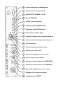
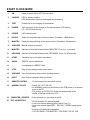
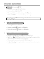
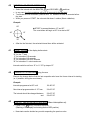
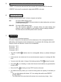
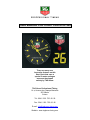
___________________________________________________________
PROFESSIONAL TIMING
USER MANUAL FOR START CLOCK HL 920
There are many new
Innovative features on this
Start Clock that uses a
special 3-motor analogue
movment developed
entirely by TAG Heuer
TAG Heuer Professional Timing
14 a, Avenue des Champs-Montants
2074 Marin
Suisse
Tel : 0041 / 032. 755. 60. 00
Fax : 0041 / 032. 755. 66. 82
E-mail : [email protected]
Website : www.tagheuer-timing.com
START CLOCK PRESENTATION
The operation of the start clock is based on a microprocessor that checks the exact position and
alignment of the clock hands every minute to ensure a total precision and reliability of the Official
Time.
Digital “Count-down” display for every start accompanied with acoustic “beeps” and the color
changes of a rotating disk that indicates valid start periods (red, green and yellow available
depending on sport regulations).
Complete control by the operator for start interval changes during the competition.
START / STOP function for start processes.
An Input for timing signals (from start gates or photocells) allows the HL 920 to take and memorize
every start time in sequential order.
An RS 232 serial data port can be used to connect a dedicated printer (such as the PTB Printer) to
print in hard copy all recorded start times as they happen. The differences between the start times
and the ideal times are also printed.
The RS 232 data port also serves as a way to control the function parameters of the HL 920 start
clock.
A supplementary output provides control signals for signal lights or additional loud speaker.
Rechargeable batteries assure excellent operational duration down to – 25° C.
The start clock can be suspended or mounted on tripod.
OPTIONS
Automated Time Setting is assured by a built-in time management system where the accuracy is
contolled by GPS or other (DCF 77) synchronization signals.
Remote Control
AVAILABLE VERSIONS
For Ski
Start validation from – 5 seconds to + 5 seconds with the ideal starting time
For Rally
Start validation at the ideal starting time
Note that from autumn 2000, it will be possible to programme the HL 920 form a PC (RS 232)
20
25-pin connector for external signals
19
9-pin connector for printer or PC
18
Switch RS 232 "NORMAL" or "IN"
8
12
Manual SYNCHRO
"BEEPS" volume adjustment
7
Positioning of the MINUTES hand.
6
Positioning of the HOURS hands
2
LED for battery condition (ON)
3
Control the charging of the rechargeable batteries
4
4-pin connector for charger or external power
5
LED external power
17
1
15-pin connector for remote control
Switch to power ON or OFF
16
Input for start impulses (working contact)
15
Input for external synchronisation
10
Selection of intervals between start "SECONDS"
9
Selection of intervals between start "MINUTES"
14
Stop of the starting process (count-down)
11
Validation for the start count-down
13
Loudspeaker for "BEEPS"
START CLOCK MODE
1
ON
Switch to power ON or OFF the start clock
2
CHARGE
LED for battery condition
LED flashes when battery is discharged (see autonomy)
3
TEST
Control key for the charging of the batteries
4
POWER
4-pin connector for the charger or for external power (12V battery)
(12 ÷ 24 VDC,see pin-out)
5
POWER
LED external power.
6
HOURS
Switch for the positioning of the hours hand. (Forwards + / Backwards -)
7
MINUTES
Switch for the positioning of the minutes hand. (Forwards + / Backwards -)
8
SYNCHRO
Manual contact for synchro.
9
MINUTES
Selection of intervals between Starts "MINUTES" (From 0 to 11 minutes)
10
SECONDS
Selection of intervals between starts "SECONDS" (From 0 to 55 seconds)
11
START
Validation key for the starts count-down
12
AUDIO
"BEEPS" volume adjustment
13
Loudspeaker for “BEEPS” Start
14
STOP
Stop of the starting process (count-down)
15
SYNCHRO
Input for external synchronisation (working contact)
16
INPUT
Input for start impulses (working contact)
17
REMOTE CONTROL
18
NORMAL / RS 232
15 pin connector for the remote control.
- Switch “IN / OUT” RS 232.
- On NORMAL position to print times on the PTB printer or to transmit
times to the PC.
- The position on RS 232 "IN" allows the programming or the
control of the Start clock from a PC.
19
COMPUTER / PRINTER
- 9-pin connector for the printer or the PC
20
EXT. CONNECTOR
- 25-pin connector for external signals.
- Control for external starting lights (5 lights-Type F1)
- Control for external lights RED – YELLOW – GREEN (same as the
disk)
- Audio line (for external loudspeaker)
- TOP SECONDE / TOP MINUTES / TOP ZERO (TOP OF THE
START)
OPERATING INSTRUCTIONS
1
POWER ON by the switch 1 "ON"
All the hands are moving to “zero” (at 12 o’clock).
In the meantime the digits indicate “88”.
The rotating disk does one rotation and stops on the RED position.
The light “CHARGE” is on and should not flash (see autonomy).
After having switched OFF the Start clock, you should wait 5 seconds before
switching it ON again.
2
TIME - OF - DAY SYNCHRONISATION
Positioning the hands at the desired time.
Hours with the switch 6 Forwards + or Backwards Minutes with the switch
3
7 Forwards + or Backwards -
SYNCHRONISATION AT THE EXACT DAY TIME
Manually, by pressing on the contact
8 SYNCHRO (Starting time).
By the Input 15 SYNCHRO (yellow and black ”banana plugs”) for a synchronisation
with several start clocks in parallel or other timing devices
We recommand to use a manual contactor (HL 18) for this operation.
If other devices have to be synchronised we recommend the use of our impulse
distributors with HL 553.
4.0
CONTROL OF START INTERVALS
Select the interval with the MINUTES 9 and SECONDS 10 switches
In any case, the first countdown will be of 30 seconds for the first start
To activate the first countdown, press START 11 between 45 and 30 seconds before
the start.
While you press on START, the coloured disk does 1 rotation (Starts validation)
Example:
60’’
✴ START is pressed between 15” and 30”.
The count-down will begin at 30” for a start at 60”.
45’’
15’’
✴
30’’
After the the first start, the selected interval time will be activated.
4.1
COUNT-DOWN of the display before starts
st
30” for the 1 start
5” for intervals of 10 seconds
10” for intervals of 15 seconds
15” for intervals of 20 to 55 seconds
30” for intervals of 1 minute and more
Intervals could be set from 10” to 11’ 55” by steps of 5”
4.2
CHANGE OF INTERVALS during the race
Execute the change before that the last competitor who have the former interval is starting
(or, if possible, during the count-down)
Example:
4.3
Intervals programmed at 30" until
12h 06’ 00’’
New interval programmation of 15" from
12h 06’ 00’’
The interval should be changed between
and
12h 05’ 30’’
12h 06’ 00’’
STOP OF THE STARTING PROCESS (Race interruption on)
Press STOP 14 during 2 seconds minimum
(Blanking of the display and rotating disk on RED position)
New starts can be decided as you wish respecting the previous rules.
5
DO NOT FORGET TO ADJUST THE VOLUME AUDIO 12
1 “BEEP” 10” before the start and the 5 last seconds with a sharper BEEP for the start.
5 "BEEPS" for the last 5 seconds with a high-pitchd BEEP for the start.
6
THE ROTATING DISK
Indicates valid start periods with 3 colours (red green and yellow)
7
SKI
The disk is RED between starts.
The disk becomes GREEN 5 seconds before the ideal starting time and return
to RED after 5 seconds.
RALLYE
The disk is RED between starts.
The disk becomes YELLOW 5 seconds before the ideal starting time
(Attention, start) and GREEN for start validation when the display indicates 0.
The disk returns to the RED position after 5 seconds.
AUTONOMY
The HL 920 has an excellent autonomy.
Of course, it depends on the state and on the maintenance of the rechargeable batteries.
With battery well charged and well maintained we can guarantee the following values with 1
Start per minute and maximum volume of the Loudspeaker.
24 hours at 20° C
15 hours at 0° C
10 hours at –20° C
8 hours at –30° C
The LED CHARGE 2 flashes when the rechargeable battery is partially discharged
(~50%)
At this moment, we recommend to use an external power supply or to recharge the Start
clock
You can control the state of charge of the battery pressing TEST 3 during 5 seconds.
If the LED 2
several hours
When the LED
is not flashing, it means that the start clock batteries are guaranteed for
2 is flashing, the key TEST should not be used.
An additional security allows you to save the timing when the capacity of the battery is
low.
- The two digits display will indicate “LO”, the rotating disk and the start “BEEPS”
will stop working
- The official time of the start clock will continue to be correct carry during ~1 hour
8
FIXATION
The start clock can be fixed on a tripod (3/8” camera thread), mounting ball, or support
We recommend to use a high quality tripods to assure the stability
In case of strong wind, we recommend to secure or stabilise the tripod with additional
weight fixed on his base.
9
USE AND FONCTIONS OF THE CHARGER
Connect the charger HL 920-3 to a normal household ac current receptacle
Connect the charger to power
4
RED LED Flashing ⇒
Very fast
The red LED is flashing faster than one flash per
second.
Batteries are totally DISCHGARGED
RED LED ON
⇒
RED LED Flashing ⇒
The LED is continually red
Batteries are CHARGING
The red LED is flashing every second.
Batteries are totally CHARGED
REMARQUE:
The Charger is also an external power supply when the start clock is working.
10
WARNING
Do not clean the plexiglas with a dry or dirty cloth
You must clean it with a wet cloth and a sweet cleaning product. (Soap and water)
If the start clock is OFF, the LED CHARGE 2 is not active when you plug the charger.
11
COMPLETE SET HL 920
1 transport case HL 920-7
1 charger 110 / 220 VAC (Type of plug to be confirmed USA / Europe) HL 920-3
1 Intermediate fixation HL 920-4 depending on the tripod type
1 operating instruction
TECHNICAL SPECIFICATIONS
General
The HL 920 is a multi-function start clock that is very precise and reliable
separate stepping motors make up this sophisticated movement to control the hours,minutes
and seconds hands.
In addition to the analogue movement, two seven-segment numeric indicators countdown the
remaining seconds to each start interval.
Further, another indicator comprised of a rotating red, green and yellow disk provides
information on start validity.
An acoustic signal rounds out the battery of indicators that serve this start clock
Start Intervals
From 10 seconds to 11 min 55 sec in 5 second increments
Time Setting
From internal RTC clock or manually
Time Base
16 MHz Thermocompensated Quartz Crystal
+/– 0,5 ppm at 20° C
+/– 2,5 ppm from –30° to 75° C
Inputs
Timing Impulses
Synchronization
Remote Control
Outputs
1 RS 232 Data output for computer or printer at 9’600 bds
25 Pin Connector with multiple outputs of timing signals for lights, additional audio systems or
other visual indicators
Temperature Range
25° C to + 75° C (without heating)
Power Supply
Internal : 12V DC rechargeable battery
External : 12-18V DC source
Autonomy
18 hours at 20° C
8 hours at – 20° C
Housing
Hot lacquered black aluminum case
Dimensions/Weight
7,3 kg
320 x 500 x 115 mm
Clock face diameter : 270 mm
digit height : 100 mm