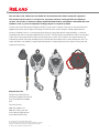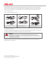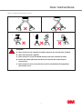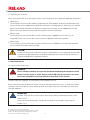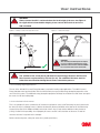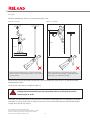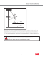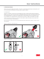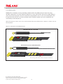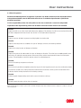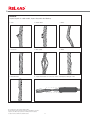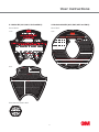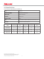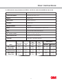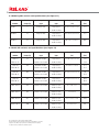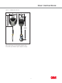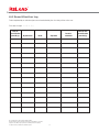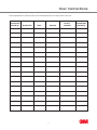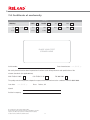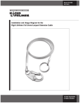
1
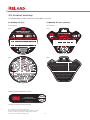
User instructions
ReLoad™ SRL
User instructions
62004-98SW-8
IMPORTANT DOCUMENT—DO NOT THROW AWAY
Mini webbing SRL
Webbing SRL
Standard cable SRL
Sealed SRL
TM
The user must read, understand and follow this instruction manual before using this equipment.
This manual must be kept in a safe place for any future reference and inspection/recertification
records. This manual is written to comply with ANSI Z359.14-2012, CSA Z259.2.2-98 and EN 365, and
should be used as part of an employee training program as required by OSHA.
Fall arrest Personal Fall Protective Equipment (PFPE) is used to arrest a worker in the event of a fall and limit forces
applied to the worker and the point of anchorage. A PFPE fall arrest system comprises a body support element
(fall arrest full body harness), a connecting element (fall arrest lanyard with built in energy absorber), a connector
carabiner/hook) and an anchorage (lifeline/anchor). The 3M™ Self-Retracting Lanyards/Devices (SRLs) are intended
to be used as connecting elements within a personal fall arrest system. SRLs include a self-locking function and
automatically extend and retract providing the user with freedom of movement over a large working area. SRLs are
to be used where user mobility is required and fall protection is needed (inspection work, general construction and
maintenance work etc.).
Manufactured for
3M Personal Safety Division
3M Center Building 235-2W-70
Saint Paul, MN 55144-1000
USA
Technical Service:
800-243-4630 in U.S.
800-267-4414 in Canada
www.3M.com/FallProtection
www.3M.com/PPESafety
© Copyright 2013 3M Company. 62004-98SW-8.
No part of this document may be reproduced or transmitted in any form or
by any means, without prior permission in writing from 3M Company.
Tel: 800-243-4630 www.3m.com/FallProtection
2
User instructions
Copyright© 2013 3M Company
No part of this manual may be reproduced or transmitted in any form or by any means, electronic or mechanical,
including photocopying, recording or any information storage or retrieval system, without prior permission in writing
from 3M Company.
IMPORTANT
You must read the entire document carefully before using this product. Please pay particular attention to all sections
which carry warning symbols and notices below.
WARNING!
This is a Warning symbol. This symbol is used throughout this document whenever
there is a risk of personal injury or death. Ensure that these warnings are read and
understood at all times.
CAUTION!
This is a Caution symbol. This symbol is used throughout this document whenever there is
a risk of damaging the 3M product. Ensure that these cautions are read and understood at
all times.
MANDATORY
This is a Mandatory symbol. This symbol is used throughout this document whenever there is
a specific instruction for the 3M product. Ensure that these mandatory instructions are read,
understood and followed at all times.
Attestation of Conformity –
Notified Body Number 0321
SATRA Technology Centre Ltd,
Wyndham Way, Telford Way,
Kettering,
Northamptonshire NN16 8SD,
United Kingdom
Tel: +44 (0)1536 410000
Production Control Phase –
Notified Body Number 0194
INSPEC Certification Services,
56 Leslie Hough Way,
Greater Manchester,
M6 6AJ,
United Kingdom
Tel: +44 (0)1617 370699
3
TM
WARNING!
This device is part of a personal fall arrest system. The user must be provided with,
read, understand and follow this instruction manual before using this equipment.
This equipment must be used and maintained as instructed. Before and during use an
emergency rescue plan must be in place, to be implemented in the event of a fall. Failure
to follow these instructions, alterations to or misuse of this equipment may result in
serious injury or death.
IMPORTANT
Contact 3M Technical Service if you have any concerns regarding the use, maintenance, applications or operation
of this device.
IMPORTANT
It is important before using this device that the product serial number on the device matches the number in
the certificate of conformity (see Section 7) and the first date of usage is recorded in the Recertification log
(see Section 6).
WARNING!
It is essential for the safety of the user that if the SRL is resold outside the original
country of destination the reseller shall provide instructions for use, for maintenance,
for periodic examination and for repair in the language of the country in which the
device is to be used.
DESCRIPTIONS:
Webbing self retracting lanyard:
Includes eyelet, integral energy absorber, self locking snap hook, and polyester webbing lanyards in lengths of 7 feet
and 12 feet x 25/32 inch, and 23 feet x 1 inch.
Cable self retracting lanyard:
Includes eyelet, integral coil energy absorber, self locking swivel snap hook, and 3/16 inch (7x19) cable (wire rope)
lanyard in a choice of galvanized or stainless steel in lengths of 23, 30, 40 and 50 feet.
Sealed cable self retracting lanyard:
Ingress protected to IP69k. Includes attachment point, integral coil energy absorber, self locking swivel snap hook
and 3/16 inch (7x19) stainless steel cable (wire rope) lanyard in lengths of 30, 50, 85 and 130 feet.
© Copyright 2013 3M Company. 62004-98SW-8.
No part of this document may be reproduced or transmitted in any form or
by any means, without prior permission in writing from 3M Company.
Tel: 800-243-4630 www.3m.com/FallProtection
4
User instructions
Contents:
1.0
2.0
3.0
4.0
5.0
Instructions for use
6
1.1
6
Applications
1.2
System requirements
1.3
Operation and use
9
12
Instructions for inspection/recertification
18
2.1
Frequency
18
2.2
Visual load indicators
19
2.3
Visual inspection
21
2.4
Action
24
2.5
Working life
24
Maintenance and storage
25
3.1
Cleaning
25
3.2
System components
25
3.3
3.4
Storage
Transportation
25
25
Product Marking
26
4.1
4.2
Webbing SRLs (7 ft)
Webbing SRLs (12 ft and 23 ft)
26
26
4.3
Cable SRLs (23 ft, 30 ft, 40 ft and 50 ft)
27
4.4
Sealed cable SRLs (30 ft, 50 ft, 85 ft and 130 ft)
27
Specifications
28
5.1
SRL materials and performance for REW-7 only
28
5.2
5.3
SRL materials and performance for REW-12, 23, REC-23, 30, 40, 50 and SREC 30, 50, 85, 130
Webbing SRL variants and specifications
29
30
5.4
Cable SRL variants and specifications
30
6.0
Recertification log
32
7.0
Certificate of conformity
34
5
TM
1.0 Instructions for use
1.1 Applications
1.1.1 Intended purpose:
The Self Retracting Lanyard (SRL) is intended to be used as a connecting element within a personal fall arrest system.
The SRL must be used vertically in situations where user mobility is required and fall protection is needed (inspection
work, general construction and maintenance work etc.). A PFPE fall arrest system comprises of a body support
element or fall arrest full body harness), a connecting element (SRL or energy absorbing lanyard), a connector
(carabiner/hook) and an anchorage (lifeline/anchor).
WARNING!
This product is intended for overhead applications only. For applications below
shoulder height, please contact 3M Technical Service.
WARNING!
Ensure there is a rescue plan in place and you are aware of the procedure before
attempting any work at height.
WARNING!
Do not modify or alter the SRL. All maintenance work is to be conducted by a 3M
authorized person.
WARNING!
If this device has been issued for your personal use only, you must read and fully
understand this manual. Once you have read this manual, if you have any concerns
regarding the use of this device contact 3M. You must ensure this manual is
fully maintained and all inspections and recertifications of this device are recorded
in the logs found at the back of this manual.
NOTE: Authorized person means a person who is trained and approved by 3M to identify hazards or dangerous conditions of the self
retracting lanyard.
© Copyright 2013 3M Company. 62004-98SW-8.
No part of this document may be reproduced or transmitted in any form or
by any means, without prior permission in writing from 3M Company.
Tel: 800-243-4630 www.3m.com/FallProtection
6
User instructions
1.1.2 Product limitations:
SRL performance may be affected by the following:
1.1.2.1 Corrosion:
Sewage and fertilizers. Do not leave the SRL in environments with exposure to sewage or fertilizers.
Corrosive environments (e.g. near seawater). More frequent inspections and recertification will be required to
ensure continued safe working use of the SRL.
1.1.2.2 Chemicals:
Chlorine environment (i.e. near swimming pool or swimming pool ventilation systems). It is recommended that
the lanyard is replaced regularly.
Acidic or caustic solutions. Do not leave the SRL in environments with exposure to acidic or caustic solutions.
If you have any concerns about using this equipment near chemical hazards, contact 3M Technical Service.
WARNING!
In the above environments it is difficult to identify defects because they may not show
on the external surface of the lanyard. It is strongly recommended that the lanyard be
replaced more frequently by an authorized person.
1.1.2.3 Direct sunlight:
The lanyard within webbing models when subjected to prolonged periods outside may deteriorate and
require replacement.
UV rays can cause the color of the lanyard to fade and may reduce its strength.
If severe discoloration is visible the lanyard must be replaced by an authorized person.
NOTE: Authorized person means a person who is trained and approved by 3M to identify hazards or dangerous conditions
of the self retracting lanyard.
1.1.2.4 High temperature environments:
3M SRLs are not designed for use in high temperatures above 130°F. Use in such environments may result in
product failure.
Use caution when using this equipment near metal cutting or similar activities.
If you have concerns regarding the use of this equipment in high temperature environments,
contact 3M Technical Service.
1.1.2.5 Environmental exposures:
3M Sealed SRL products are rated to IP69K and are able to withstand high-pressure and steam cleaning.
7
TM
1.1.2.6 Electrical dangers:
WARNING!
This product must not be used if there is any risk of the SRL contacting high voltage
power lines. This warning also includes webbing type devices because moisture can be
absorbed by the lanyard providing a path for electrical current.
1.1.2.7 Capacity:
SRLs are only to be used by those of a combined mass (person, clothing, tools, etc.) of 310 pounds (140 kg)
maximum (webbing SRLs) or 400 pounds (181 kg) maximum (cable and Sealed SRLs).
An SRL is for the use of a single user only. No more than one person can connect to an SRL.
1.1.2.8 Locking speed:
To ensure positive locking of the SRL, a clear, unobstructed fall path is necessary.
Do not use an SRL if the fall path is obstructed.
Do not use the SRL when working on materials such as sand or grain because this may not allow sufficient speed
to cause the SRL to lock in the event of a fall.
1.1.2.9 Health:
WARNING!
Fitness and age significantly affect a person’s ability to safely withstand
fall arrest loads.
The following are among the medical conditions that could affect the safety of
the user:
Heart disease/chest pain.
High blood pressure.
Epilepsy, fits, blackouts.
Fear of heights/vertigo.
Impaired limb function.
Alcohol or drug dependence.
Psychiatric illness.
Diabetes.
If you are uncertain about your ability, consult your doctor.
3M SRLs must not be used by pregnant women or minors.
© Copyright 2013 3M Company. 62004-98SW-8.
No part of this document may be reproduced or transmitted in any form or
by any means, without prior permission in writing from 3M Company.
Tel: 800-243-4630 www.3m.com/FallProtection
8
User instructions
1.1.2.10 Training:
Both the user and purchaser of this equipment are responsible for ensuring they read and understand these
instructions in full. They should be trained in the correct care and use of this equipment, and should be aware of
the operation, the limitations, and the consequences of incorrect use of this equipment.
IMPORTANT
Never expose a trainee to a fall hazard. Training must be repeated on a periodic basis.
WARNING!
Only persons who have undergone the necessary work at height training and have read
and understood this manual may use the 3M SRL.
1.2 System requirements
1.2.1 Suitability of components:
The 3M SRLs are designed for use with compatible components and subsystems or approved components and
subsystems. The integration of unapproved components can lessen the safety of the complete system.
1.2.2 Suitability of connectors:
All connectors (such as hooks, carabiners and D-rings) must be compatible with the anchorage point and other
system components. To ensure connectors are suitable to be used with other system components they must be
able to connect in such a way that their size and shape do not affect the performance and safety of the connectors.
Contact 3M Technical Service if you have any concerns about connector compatibility.
WARNING!
Do not use equipment that is not suitable (See Figure 1). All connectors must
be capable of supporting loads of at least 5,000 lbs (22 kN). All snap hooks and
carabiners must be self locking (refer to relevant national standards).
9
TM
Attachment points with an unusual shape or attachment points that are undersized, when used in conjunction with
connectors, can be orientated in such a way that allows forces to be applied to the gate of a snap hook or carabiner.
This force may cause the connector to open allowing the connector to unlock from the attachment point. Figure 1
shows unintentional ‘rollout’.
Figure 1—Unintentional disengagement (rollout).
1. Load is applied to the connector.
2. The attachment point presses
against connector gate.
3. The gate is now open allowing the
snap hook to disengage.
1.2.3 Making connections:
It is the user’s responsibility to ensure that the correct connector is used for the intended application, by making sure
that all of the connectors are compatible with each other in size, shape and strength.
WARNING!
Always ensure all connectors are correctly engaged and locked. Do not use
combinations of components or subsystems that may affect or interfere with the
safe function of each other.
3M approved connectors (snap hooks and carabiners) are designed to be used only as they are specified in the
relevant product’s user instructions.
© Copyright 2013 3M Company. 62004-98SW-8.
No part of this document may be reproduced or transmitted in any form or
by any means, without prior permission in writing from 3M Company.
Tel: 800-243-4630 www.3m.com/FallProtection
10
User instructions
Figure 2—Inappropriate anchorage connections
A
C
B
D
E
WARNING!
A. Never connect to a D-ring where another connector has already been attached.
B. Never link connectors together.
C. Never connect in a way that would load the gate of the carabiner or hook.
D. Ensure the anchor point does not obstruct or prevent the connector gate
from closing.
E. Never connect in such a way that may result in unintentional disengagement
(See Section 1.2.2).
11
TM
1.2.4 Anchorage structure:
When connecting the SRL to an anchorage structure, the anchorage used must comply with applicable requirements.
Within the US
The anchorage structure must be capable of supporting static loads applied in all direction permitted by the fall
arrest system of at least 3,600 pounds (16 kN) with certification of a qualified person. Alternatively, if a qualified
person cannot provide certification, the minimum strength of the anchorage must be 5,000 pounds (22 kN).
Refer to local, state, governmental or jurisdictional agencies for further information.
Within Canada
The anchorage structure must be able to sustain a minimum force of 5,000 pounds (22.5 kN). It is the
responsibility of the user to ensure that anchors conform to applicable government regulations.
Within Europe
The anchorage structure must be able to sustain a minimum force of 2,700 pounds (12 kN). 3M recommends
using a certified anchor point. Refer to EN 795.
CAUTION!
If more than one personal fall arrest system is attached to the same supporting structure then
the former strength requirements have to be multiplied by the number of personal fall arrest
systems attached to the supporting structure.
1.3 Operation and use
1.3.1 Preparation before use:
WARNING!
Do not attempt to modify or repair the equipment. Modifying the equipment could
result in serious injury or death. Always consult 3M Technical Service if you need
to use this equipment in any way other than described in this manual.
Carefully inspect this equipment as instructed in Section 2.0 before each use.
Before connecting to your fall protection system, ensure you fully understand how to use it, an inspection has been
carried out and a rescue plan is in place. Always be aware of any other factors that could affect your safety while
using the equipment.
MANDATORY
Rescue: There must be a rescue plan in place and an ability to implement the plan in the
event of a fall.
Always ensure the anchorage is capable of sustaining fall arrest loads. Please refer to
Section 1.2.4.
© Copyright 2013 3M Company. 62004-98SW-8.
No part of this document may be reproduced or transmitted in any form or
by any means, without prior permission in writing from 3M Company.
Tel: 800-243-4630 www.3m.com/FallProtection
12
User instructions
WARNING!
Always ensure the SRL is anchored above the head height of the user. See Figure 3.
For applications below shoulder height, please contact 3M Technical Service at
800-243-4630.
Figure 3—Always locate anchorage above user.
Figure 4—Sealed anchorage.
Main anchor
connection
30°
MAX
Secondary
retention point
WARNING!
The secondary retention point can only be
used as a method of tethering the Sealed
SRL back to the structure and must NEVER
be used as the main anchor connection.
WARNING
The addition of the 2 foot (0.6 m) 3M 3012 Personal Energy Absorber will increase
the clearance requirements by 5½ feet (1.6 m). The additional distance must be
taken into consideration during the clearance calculation process.
1.3.1.1 Leading edge applications:
The use of the 3M 3012 Personal Energy Absorber is required in leading edge applications. The 3012 Personal
Energy Absorber must be placed inline with the Self Retracting Lanyard to add energy absorption properties at the
user end of the system. The additional energy absorption properties will keep forces below the cable sheer strength in
the event of a fall over leading edge.
1.3.1.2 Calculate fall clearance:
This is an example of how to calculate the fall clearance requirements using a Self Retracting Lanyard connected to
the dorsal D-ring of a full body harness. Add the deceleration distance identified on the label of the Self Retracting
Lanyard (3 feet per OSHA 1910 and 1926) to the slide of the D-ring (1 foot) and the additional safety clearance
(2 feet), to allow for the possibility of an improperly fit harness and/or a miscalculation of distances. A total fall
clearance of 6 feet is required for this example.
Before commencing work, always be aware of any moving machinery.
13
TM
WARNING
Always ensure that you work a safe distance from moving machinery, and that all
components in a system cannot be damaged by any moving machinery.
1.3.2 Using the SRL:
Attach the SRL overhead to a suitable anchorage or anchorage connector. Ensure that rollout cannot occur when
using a hook or carabiner to make a connection as specified in Section 1.2.2 and 1.2.3.
Perform an operational check of the device before connecting the self locking snap hook to the harness. To check
operation pull smoothly on the lanyard and listen for the audible signal (clicking), then pull sharply on the lanyard to
engage the locking mechanism.
A full body harness must be worn when using the SRL. Always ensure that you attach to a designated fall arrest
attachment point on the harness. Situations where fall paths are obstructed must be avoided.
WARNING!
Never use a body belt for any fall arrest applications.
Always use a full body harness.
REW – 23, REC – 23, 30, 40, 50 and SREC 30, 50, 85, 130—connect the self locking snap hook on the end of the
lanyard to the designated fall arrest attachment point of a full body harness.
REW – 7, 12—the self locking snap hook can be attached to either the designated fall arrest attachment point of a
full body harness or the anchorage/anchorage connector.
Figure 5—Only REW -7, 12 have the option to attach to the designated fall arrest attachment point or attachment point on the full
body harness. All other SRLs must connect to anchorage / anchorage connector
Anchorage /
Anchorage
Connector
SRL
Connector
Anchorage /
Anchorage
Connector
SRL
Connector
© Copyright 2013 3M Company. 62004-98SW-8.
No part of this document may be reproduced or transmitted in any form or
by any means, without prior permission in writing from 3M Company.
Tel: 800-243-4630 www.3m.com/FallProtection
Anchorage /
Anchorage
Connector
SRL
Connector
14
Anchorage /
Anchorage
Connector
SRL
Connector
User instructions
Ensure all connections are compatible in size, shape, and strength. Make sure the snap hook or carabiner gate
is securely closed and locked. Always ensure that you follow the manufacturer’s supplied instructions with each
component of a system.
Once connected to the SRL the user is free to move about the working area. The lanyard will extract and retract
without hesitation. If the lanyard is prevented from retracting during normal use, extract the lanyard fully and allow
it to retract under tension. Then check the locking function of the device. If the lanyard continues not to retract fully,
then return the SRL to an authorized person for inspection and recertification.
An increase in fall distance can occur if the lanyard is prevented from retracting. This must be avoided. Therefore,
always ensure that the lanyard can extract and retract without hesitation, and never prevent the lanyard from
retracting (see Figure 6).
During use, sudden or quick movements can cause the SRL to lock up, and should, therefore, be avoided.
Never attach an additional lanyard or similar component to lengthen the lanyard.
Do not allow the lanyard to pass through legs or under arms.
In the event of a fall, the SRL will lock, arrest the fall, and deploy the energy absorber when used properly.
After rescue the SRL should be removed from use and recertified by an authorized person.
MANDATORY
In the event of a fall: If a fall has occurred on an SRL, it must be removed from service and
recertified by an authorized person.
WARNING! Do not allow the lanyard to be in contact with or rub against sharp edges or
abrasive surfaces.
WARNING!
It is essential to safety that the anchor device and anchor point should always be
positioned, and work carried out in such a way, as to minimize the potential for a fall.
See examples of free fall situations to be avoided in Figures 6 and 7.
WARNING!
An increase in fall distance can occur if the lanyard is prevented from retracting.
This must be avoided.
NOTE: Authorized person means a person who is trained and approved by 3M to identify hazards or dangerous conditions of the self
retracting lanyard.
15
TM
Free fall
Maximum allowable free fall for a self retracting lanyard is 2 feet.
Figure 6—Free falls
Figure 7—Free falls
Freefall
Freefall
Always ensure the lanyard retracts correctly. If the lanyard
does not retract correctly a freefall situation could occur and
must be avoided.
Always ensure the SRL is anchored above your head.
If anchored below shoulder height, a freefall greater than
2 feet could occur and must be avoided.
Always ensure that free fall situations greater than 2 feet are avoided (see Figures 6 and 7) in order to help avoid
potential product failure.
Always ensure swing falls are avoided (see Figure 8).
WARNING!
Striking objects horizontally due to the pendulum affect of a swing fall may cause
serious injury or death.
Swing falls must be prevented by ensuring that work is conducted as directly below the anchorage point as possible.
Swing falls can cause serious injury. A swing fall can result in an increased freefall distance requiring more distance
to safely arrest the fall. See Figure 8.
© Copyright 2013 3M Company. 62004-98SW-8.
No part of this document may be reproduced or transmitted in any form or
by any means, without prior permission in writing from 3M Company.
Tel: 800-243-4630 www.3m.com/FallProtection
16
User instructions
Figure 8—Swing falls
Swing
fall
hazard
Working
level
Lower
level
When the SRL is not in use, do not allow the lanyard to be fully extracted for long periods of time because this may
cause weakening of the retraction spring. Do not let go of the lanyard because it will retract at high speed potentially
damaging internal parts. Instead, allow the device to retract back into the SRL slowly and under controlled tension.
If the SRL is positioned high above the users head, the use of a tag line/second line is acceptable to allow the SRL to
fully retract.
WARNING!
Tag lines/second lines must be removed from the device before use.
Never use a tag line other than as described in this manual.
17
TM
2.0 Instructions for inspection/recertification
WARNING!
Regular and periodic examinations of the SRL are required to ensure the safety of
the user, which is dependent on the continued efficiency and durability of the SRL.
If inspection reveals any defect, inadequate maintenance, or unsafe condition,
immediately remove SRL from service for authorized repairs or disposal.
2.1 Frequency:
2.1.1 Before each use:
The user must carry out a pre-use inspection of the equipment to ensure that it operates correctly before use.
See Sections 2.2, 2.3 and 2.4 for inspection guidelines.
2.1.2 Periodically:
An inspection should be completed by an authorized person other than the user. See Sections 2.2, 2.3 and 2.4.
It is the responsibility of the site safety officer or the user to maintain a record of each periodic
inspection in the inspection log, which can be found at the back of this manual. See Section 6.
2.1.3 Annually:
A. An inspection of the SRL must be completed by a competent person other than the user. Contact 3M Technical
Service for additional information.
B. Every recertification must be recorded in the recertification log. It is mandatory that a factory authorized
recertification of this product be completed within 2 years of manufacture and annually thereafter. However, local
legislation may indicate more frequent recertification intervals. It is the responsibility of the site safety officer
or the user to comply with all local or jurisdictional safety requirements, including to maintain a record
of each annual recertification in the recertification log, which can be found in the back of this manual.
See Section 7.
NOTE: Authorized person means a person who is trained and approved by 3M to identify hazards or dangerous conditions of the self
retracting lanyard.
WARNING!
Only 3M, or parties authorized by 3M in writing, may make repairs or undertake
recertification of this equipment.
WARNING!
If the SRL has been subjected to fall arrest or impact forces, or you are in any doubt
concerning the safety or condition of the device, it must be removed from service
immediately and recertified by an authorized person.
© Copyright 2013 3M Company. 62004-98SW-8.
No part of this document may be reproduced or transmitted in any form or
by any means, without prior permission in writing from 3M Company.
Tel: 800-243-4630 www.3m.com/FallProtection
18
User instructions
2.2 Visual load indicator:
3M manufactures both webbing and cable SRLs. These SRLs contain different load indicators to indicate when a fall
has occurred. Different load indicators will require different inspection methods.
2.2.1 Cable SRL:
Cable SRLs incorporate a constant force energy absorbing coil and/or an impact indicating snap hook designed to
deploy in the event of a fall. This will result in the coil protruding from the top of the SRL or the impact indicator on the
hook showing deployment. To inspect the visual load indicator, visually examine the SRL for any exposed red color
on the absorber coil or snap hook indicator. (See Figure 9). If any red color is visible on the absorber coil or impact
indicator snap hook, then loading has occurred. SRLs that have been subjected to loading must be removed from
service and recertified by an authorized person.
NOTE: Authorized person means a person who is trained and approved by 3M to identify hazards or dangerous conditions of the self
retracting lanyard.
Figure 9a—Deployment of cable energy absorber
Figure 9b—Impact indicating snap hooks showing exposed red
warning color once deployed
19
TM
2.2.2 Webbing SRL:
Webbing SRLs incorporate an energy absorbing component within the webbing lanyard. Inspect the energy
absorber to determine if it has been deployed. Deployment is clearly indicated by a red warning symbol displayed
on the lanyard (See Figure 10). Ensure the clear plastic energy absorber cover is secure and not damaged or torn.
If inspection reveals the SRL has received an impact load it should be removed from service immediately and
recertified by an authorized person.
NOTE: Authorized person means a person who is trained and approved by 3M to identify hazards or dangerous conditions of the self
retracting lanyard.
Figure 10—Deployment of tear webbing absorber
BEFORE USE/AS SUPPLIED
DEPLOYED VISUAL LOAD INDICATOR
Red warning symbol visible, indicates deployment/fall arrest
© Copyright 2013 3M Company. 62004-98SW-8.
No part of this document may be reproduced or transmitted in any form or
by any means, without prior permission in writing from 3M Company.
Tel: 800-243-4630 www.3m.com/FallProtection
20
User instructions
2.3 Visual inspection:
Perform the following checks in sequence. If you have any doubts about any of the inspection checks
to be performed below, consult 3M Technical Service or an authorized person who is qualified to
perform inspections.
It is the responsibility of the site safety officer or the user to maintain a record of each periodic
inspection in the inspection log, which can be found at the back of this manual. See Section 6.
Check 1.
Inspect the SRL to see if the visual load indicator has deployed. This indicates if a fall has occurred and if the SRL
has been subjected to fall arrest loads. See Section 2.2 for load indicator inspection.
Check 2.
Inspect to ensure all labels are present and fully legible. See Section 4.0.
Check 3.
Inspect connecting hooks or carabiners for signs of damage, corrosion, and working condition.
Check 4.
Inspect the casing for signs of damage or distortion.
Check 5.
Inspect the eyelet on all cable models for signs of damage or distortion. The swivel eye on webbing models must
turn freely, the spiral pin must be present and securely fixed, and the fastening bolt must be flush with eyelet
surface. If fastening bolt is sub-flush, please contact an authorized person.
Check 6.
Ensure all fastenings are present and secure.
Check 7.
Ensure that it is possible to completely extract the lanyard. As the lanyard retracts it must do so without hesitation
(no slack line should occur). During extraction and retraction ensure that a clicking sound can be heard which
indicates that the locking mechanism is functioning correctly.
Check 8.
Pull the lanyard sharply making sure that this causes the device to lock up.
Check 9.
Visually inspect the entire unit for signs of corrosion.
NOTE: Authorized person means a person who is trained and approved by 3M to identify hazards or dangerous conditions of the self
retracting lanyard.
21
TM
Check 10.
Inspect lanyard. On cable models, inspect lanyard for the following:
1. Cuts
2. Broken wires
3. Kinks
4. Corrosion
5. Bird-caging
6. Weld
7. Abraded areas
8. Inspect the ferrules for corrosion, cracks or damage by sliding up cable.
© Copyright 2013 3M Company. 62004-98SW-8.
No part of this document may be reproduced or transmitted in any form or
by any means, without prior permission in writing from 3M Company.
Tel: 800-243-4630 www.3m.com/FallProtection
22
User instructions
Check 11.
Inspect lanyard. On web models, inspect lanyard for the following:
1. Broken stitching
2. Frayed strands
3. Cut/sliced
4. Excessive soiling
5. Localized wearing
6. Burnt web
7. Deteriorated sections
Also inspect for discoloration of the lanyard, possibly caused by chemical
attack, heat, or ultraviolet light. Regularly check lanyard for the presence
of metal or wood splinters on its surface, metal splinters will reduce the
wear resistance of the lanyard.
23
TM
2.4 Action:
If a defect is revealed during inspection or operation, the SRL must be removed from service and an authorized
person should be contacted for recertification.
NOTE: Authorized person means a person who is trained and approved by 3M to identify hazards or dangerous conditions of the self
retracting lanyard.
2.5 Working life:
The lanyard within webbing models when subjected to prolonged periods outside may deteriorate. UV rays can cause
the color of the lanyard to fade and may reduce its strength. If significant discoloration is visible, the lanyard must be
replaced by an authorized person.
The life of the product can be affected by environmental conditions. If, during periodic inspection by a competent
person, the product is deemed unsafe it should be removed from service. Under the proper conditions and with
proper use, the service life of SRL webbing has been evaluated to be up to 10 years.
WARNING!
The following factors such as (but not limited to): environmental conditions
(e.g. contact with chemicals, exposure to temperatures >60°C (>140°F)), incorrect
storage, frequency of use, may reduce service life. If the lanyard fails inspection,
it must be replaced by an authorized person.
© Copyright 2013 3M Company. 62004-98SW-8.
No part of this document may be reproduced or transmitted in any form or
by any means, without prior permission in writing from 3M Company.
Tel: 800-243-4630 www.3m.com/FallProtection
24
User instructions
3.0 Maintenance, servicing and storage
3.1 Cleaning:
If required, clean the SRL’s exterior with warm water (<100ºF) and non biological detergent. Position the SRL
such that any excess water can drain out. Clean labels as required in order to maintain legibility.
Clean the lanyard with water and non biological detergent. Rinse and towell dry lanyard leaving fully retracted device
to dry naturally in a sheltered and ventilated place. Do not place near sources of heat. An excessive buildup of dust,
dirt and paint etc, may compromise the retraction of the lanyard. If there is an excessive dirt build up ensure that the
lanyard is replaced by an authorized person.
WARNING!
If the lanyard comes into contact with acids, remove the unit from service and return
the SRL to an authorized person for lanyard replacement.
Lanyard replacement and any further maintenance must be completed by an authorized person. DO NOT
disassemble the SRL. For inspection intervals please refer to Section 2.1.
3.2 System components:
The full body harness and any other system components should be cleaned and stored according to manufacturer’s
instructions.
NOTE: Authorized person means a person who is trained and approved by 3M to identify hazards or dangerous conditions of the self
retracting lanyard.
3.3 Storage:
Store the SRL in a cool, dry, clean environment. Ensure SRL is away from dust and oil and direct sunlight. Inspect the
SRL after long periods of storage.
3.4 Transportation:
During transportation of this device, protection must be provided in order to prevent damage or contamination.
25
TM
4.0 Product marking
The following labels should be attached and fully legible on each SRL.
4.1 Webbing SRL (7 ft)
4.2 Webbing SRL (12 ft and 23 ft)
Case labels:
Case labels:
Front
Front
N/A
N/A
N/A
N/A
Rear
Rear
TO STRUCTURAL
ANCHOR POINT
Warning: Follow the manufacturer’s instructions included with this product at
the time of shipment. Only one user to be connected to this device at any time.
Alteration or misuse of this product, or failure to follow instructions may result in
serious injury or death. This device must be removed from service immediately
when the visual load indicator is deployed. See other markings. Avertissement:
Observer les consignes du fabricant accompagnant ce produit. Ne jamais
relier plus d’un seul utilisateur à cet appareil. Toute modification ou mauvais
usage du produit, ou non-observation des consignes, peut entraîner
blessure grave ou mort d'homme. Retirer le produitdu service dès que
l'indicateur de charge est déployé. Voir les autres marquages.
Use: Minimum rigid anchor strength 5000 lbs
(22 kN). Anchor device directly above working
area at an angle no greater than 30º from vertical.
For anchorages below shoulder level refer to
user manual. Always ensure lifeline is in
tension when in use. Full body harness
must be used when connected to this
device. Use caution when lifeline is
used near sharp edges. For use
by trained personnel only.
Inspection: Inspect before use. This must include: activating the audible clicking
mechanism, testing the locking and retracting function, lifeline, condition of connectors,
housing and fasteners, legibility of labels, and any evidence of defects damage or
missing parts. Inspection by a competent / authorized person is required at least
annually. Do not use if inspection reveals an unsafe condition. Contact
3M for service / repair. The manufacturer or manufacturer-approved
service agent shall record the findings of this service and label the
product with the next annual service date / Le fabricant ou
réparateur agréé devra enregistrer les résultats de cet entretien
et devra apposer une étiquette sur le produit mentionnant
la date du prochain entretien annuel.
62007-30SW_Issue 7
Webbing Shock Absorber Label:
N
Tel: 800-243-4630
www.3m.com/FallProtection
S
F
15 16 A
A
62004-41SW_Issue 4
D J
13 14 M
O
J
J
M
The date of manufacture will be indicated.
© Copyright 2013 3M Company. 62004-98SW-8.
No part of this document may be reproduced or transmitted in any form or
by any means, without prior permission in writing from 3M Company.
Tel: 800-243-4630 www.3m.com/FallProtection
26
User instructions
4.3 Cable SRL (23 ft, 30 ft, 40 ft and 50 ft)
4.4 Sealed cable SRL (30 ft, 50 ft, 85 ft and 130 ft)
Case labels:
Case label:
Front
Front
Tel: 800-243-4630 www.3M.com/FallProtection
Made in UK / Fabriqué au Royaume-Uni
Lifeline Material/Matériau de longe: Ø3/16 in.(Ø5mm) Stainless Steel Cable/Câble en acier inoxydable
ANSI
CLASS B
Z359.14-2012
OSHA
29 CFR
1910.66
1926.502
CSA
TYPE 2
Z259.2.2-98
Arrest Distance/
Distance d’arrêt
max
54 in.
(1372mm)
42 in.
(1067mm)
55 in.
(1.4m)
Free Fall Limit/
Distance max.
de chute libre
24 in.
(610mm)
24 in.
(610mm)
24 in.
(0.6m)
Max Arresting Force/
Force d’arrêt max
1800 lbs
(8kN)
1800 lbs
(8kN)
1800 lbs
(8kN)
Meets/
Remplit
Avg. Arresting Force/
Force d’arrêt moyenne
Max Capacity/
Capacité
N/A
900 lbs
(4kN)
N/A
N/A
130 - 310 lbs
(59 - 141 kg)
310 lbs
(141 kg)
310 lbs
(141 kg)
:
Serial #/
N° de série:
Inspection: Inspect before use. This must
include: activating the audiable clicking mechanism,
testing the locking and retracting function, lifeline,
condition of connectors, housing and fastenersand
any evidence of defects damage or missing parts.
Inspection by a competent / authorised person is
required at least annually. Do not use if
inspection reveals an unsafe condition. Contact
3M for service / repair. The manufacturer or
manufacturer approved service agent shall
record the findings of this service and label the
product with the next annual service date.
Le fabricant ou répareur agréé devra
enregistrer les résultats de cet entretien et
devra apposer une étiquette sur le produit
mentionnant la date du prochain entretien
annuel.
Warning: Follow the manufacturer’s
instructions included with this product
at the time of shipment. Alteration or misuse of
this product, or failure to follow instructions may
result in serious injury or death. This device must
be removed from service immediately when the
visual load indicator is deployed. See other
markings.
Avertissement: Observer les consignes du fabricant
accompagnant ce produit. Ne jamais relier plus d’un
seul utilisateur à cet appareil. Toute modification ou
mauvais usage du produit, ou non-observation des
consignes, peut entraîner blessure grave ou mort
d’homme. Retirer le produit du service dès que
l’indicateur de charge est déployé. Voir les autres
marquages.
N/A
Part #/Réf. de
pièce: SREC-30-SS
3M ID: 70071605904
Use: Minimum rigid anchor strength 5000 lbs (22
kN). Only one user to be connected to this device
at any time. Anchor device directly above working
area at an angle no greater than 30° from vertical.
For anchorages below shoulder level refer to user
manual. Always ensure lifeline is in tension when in
use. Full body harness must be used when connected
to this device. Use caution when lifeline is used near
sharp edges. For use by trained personnel only.
WARNING - This device is for overhead use only. Not suitable for horizontal use. Suitable for
use with approved 3M Horizontal Lifelines. AVERTISSEMENT - Cet appareil ne doit s’utiliser
qu’en hauteur. Ne convient pas à une utilisation horizontale.
Visual Load Indicator:
Inspect hook for any exposed red color.
If any red color is visible on the hook
then loading has occurred. The device
must be removed from service.
DO NOT USE.
Rear
TO
Warning: Follow the
STRUCTURAL
manufacturer’s instruction
ANCHOR POINT
included with this
product at the time of shipment. Only one user to be connected to this
device at any time. Alteration or misuse of this product, or failure to
follow instructions may result in serious injury or death. This device must
be removed from service immediately when the visual load indicator is
deployed. See other markings. Avertissement: Observer les consignes
du fabricant accompagnant ce produit. Ne jamais relier plus d’un seul utilisateur
à cet appareil. Toute modification ou mauvais usage du produit, ou non-observation
des consignes, peut entraîner blessure grave ou mort d'homme. Retirer le produit du service dès que
l'indicateur de charge est déployé. Voir les autres marquages.
Use: Minimum rigid anchor strength
5000 lbs (22 kN). Anchor device
directly above working area at an
angle no greater than 30º from
vertical. For anchorages below
shoulder level refer to user
manual. Always ensure
lifeline is in tension when in
use. Full body harness must
be used when connected
to this device. Use caution
when lifeline is used
near sharp edges.
For use by trained
personnel only.
Inspection: Inspect before use. This must include: activating
the audible clicking mechanism, testing the locking and retracting
function, lifeline, condition of connectors, housing and fasteners,
legibility of labels, and any evidence of defects damage or
missing parts. Inspection by a competent /authorized person
is required at least annually. Do not use if inspection reveals
an unsafe condition. Contact 3M for service / repair.
The manufacturer or manufacturer-approved service
agent shall record the findings of this service and
label the product with the next annual service date /
Le fabricant ou réparateur agréé devra enregistrer
les résultats de cet entretien et devra apposer
une étiquette sur le produit mentionnant la date
du prochain entretien
-43SW_Issue 7
annuel.
62207
Next Service Date Label:
Da
t
t se
f nex rvice
eo D J
N
F
14 15 M
O
S
16 17 A
A
62
002
J
J
M
-50_Iss ue
1
27
TM
5.0 Specifications
5.1 SRL materials and performance for REW-7 only
Case
Aluminium
Pawl/ratchet module
Hard lubricated stainless steel
Motor spring
Stainless spring steel
Fasteners
Stainless steel
Hub/drum module
Nylon
Web
25/32 (20 mm) x 1/16 Inch (1.6 mm) Polyester with Vectran™ core
Pawl type
Full Contact™ anti-ratchet (patented)
Meets
Max
arrest distance
Free
fall limit
Max
arresting force
Avg.
arresting force
Max
capacity
ANSI - CLASS B
Z359.14-2012
54 in.
(1372 mm)
24 in.
(610 mm)
1800 lbs
(8 kN)
900 lbs
(4 kN)
130 - 310 lbs
(59 - 141 kg)
OSHA 29 CFR
1910.66/1926.502
42 in.
(1067 mm)
24in.
(610mm)
1800 lbs
(8 kN)
N/A
310 lbs
(141 kg)
CSA - TYPE 1
Z259.2.2-98
55 in.
(1.4 m)
24 in.
(0.6 m)
1800 lbs
(8 kN)
N/A
310 lbs
(141 kg)
© Copyright 2013 3M Company. 62004-98SW-8.
No part of this document may be reproduced or transmitted in any form or
by any means, without prior permission in writing from 3M Company.
Tel: 800-243-4630 www.3m.com/FallProtection
28
User instructions
5.2 SRL materials and performance for REW-12, 23, REC-23, 30, 40, 50 and SREC 30, 50, 85, 130
Case
Impact modified nylon or aluminium (sealed)
Pawl/ratchet module
Hard lubricated stainless steel
Chassis
Stainless steel
Motor spring
Stainless spring steel
Fasteners
Stainless steel
Hub/drum module
Aluminium
Cable
3/16 inch (5 mm) (7x19) Galvanized or stainless steel
Web
1 inch (25 mm) x 5/64 (2 mm) Polyester
CF® absorber module
Stainless steel/nylon (patented)
Energy absorber type
Constant Force® in-line (patented)
Pawl type
Full Contact™ anti-ratchet (patented)
Max capacity
Meets
Max arrest
distance
Free fall
limit
Max
arresting
torce
Avg.
arresting
force
Web SRL
Cable SRL
ANSI - CLASS B
Z359.14-2012
54 in.
(1372 mm)
24 in.
(610 mm)
1800 lbs
(8 kN)
900 lbs
(4 kN)
130 - 310 lbs
(59 - 141 kg)
130 - 310 lbs
(59 - 141 kg)
OSHA 29 CFR
1910.66/1926.502
42 in.
(1067 mm)
24in.
(610mm)
1800 lbs
(8 kN)
N/A
310 lbs
(141 kg)
400 lbs
(181 kg)
CSA - TYPE 2
Z259.2.2-98
55 in.
(1.4 m)
24 in.
(0.6 m)
1800 lbs
(8 kN)
N/A
310 lbs
(141 kg)
310 lbs
(141 kg)
29
TM
5.3 Webbing SRL variants and specifications (See Figure 11)
Model
number
Working
range (ft)
Lanyard
type
Hook
type
Size (L x W x D)
(in)
Weight
(lbs)
REW-7
7
Vectran™ web
Forged steel,
double locking
4 3 /8 x 3 11/16 x 2 3 /8
3.4
REW-12
12
Polyester web
Forged steel,
double locking
8 11/16 x 5 9 /16 x 3 7/8
5.3
REW-23
23
Polyester web
Forged steel,
double locking
10 13 /16 x 7 5 /16 x 5
9.6
5.4 Cable SRL variants and specifications (See Figure 11)
Model
number
Working
range (ft)
Lanyard
type
Hook
type
Size (L x W x D)
(in)
Weight
(lbs)
REC-23
REC-23-SS
23
Galvanized cable
Stainless steel cable
Forged steel,
double locking
13 x 6 11/16 x 4 13 /16
11.5
11.4
REC-30
REC-30-SS
30
Galvanized cable
Stainless steel cable
Forged steel,
double locking
14 1/16 x 7 5 /16 x 5
13.3
13.2
REC-40
REC-40-SS
40
Galvanized cable
Stainless steel cable
Forged steel,
double locking
15 9 /16 x 8 7/16 x 5 1/8
16
15.8
REC-50
REC-50-SS
50
Galvanized cable
Stainless steel cable
Forged steel,
double locking
15 9 /16 x 8 7/16 x 5 1/8
16.6
16.4
SREC-30-SS
30
Stainless steel cable
Stainless steel,
double locking
9 1/ 2 x 9 1/ 2 x 7
21.4
SREC-50-SS
50
Stainless steel cable
Stainless steel,
double locking
11 x 11 x 8
27.7
SREC-85-SS
85
Stainless steel cable
Stainless steel,
double locking
13 1/4 x 13 1/4 x 8
48.3
SREC-130-SS
130
Stainless steel cable
Stainless steel,
double locking
15 x 15 x 8 1/2
62
© Copyright 2013 3M Company. 62004-98SW-8.
No part of this document may be reproduced or transmitted in any form or
by any means, without prior permission in writing from 3M Company.
Tel: 800-243-4630 www.3m.com/FallProtection
30
User instructions
Figure 11 – webbing and cable SRLs.
W
D
L
WORKING
RANGE
Note: Hook shown is for illustration purposes only.
Exact hook specification may be subject to change.
31
TM
6.0 Recertification log
To be completed by an authorized person and maintained by the site safety officer or the user.
First date of usage: mm / dd / yy
Date of
recertification
(mm/dd/yy)
Organization
Name
© Copyright 2013 3M Company. 62004-98SW-8.
No part of this document may be reproduced or transmitted in any form or
by any means, without prior permission in writing from 3M Company.
Tel: 800-243-4630 www.3m.com/FallProtection
Signature
32
Results/
comments
Date of next
recertification
(mm/dd/yy)
User instructions
To be completed by an authorized person and maintained by the site safety officer or the user.
Date of
recertification
(mm/dd/yy)
Organization
Name
Signature
33
Results/
comments
Date of next
recertification
(mm/dd/yy)
TM
7.0 Certificate of conformity
Product
Webbing
7 ft
12 ft
23 ft
Cable
Sealed
S/S
Galv
23 ft
30 ft
40 ft
50 ft
85 ft
130 ft
PLACE LOCK TEST
STICKER HERE
Serial number:
Date of manufacture: mm / dd / yy
We certify that this item has been inspected and conforms to the full requirements and specifications of the
relevant Standards: (tick applicable box)
ANSI Z359.14-2012
CSA Z259.2.2-98
EN 360:2002
The quality control arrangements adopted in respect of this item conforms to the conditions of EN ISO 9001:2000.
Issue date:
mm / dd / yy
Place:
Devizes, UK
Signed:
Position in company:
© Copyright 2013 3M Company. 62004-98SW-8.
No part of this document may be reproduced or transmitted in any form or
by any means, without prior permission in writing from 3M Company.
Tel: 800-243-4630 www.3m.com/FallProtection
34
User instructions
Notes
35
Webbing
Cable
Sealed
0
10
20
30
40
50
60 length ft 70
80
90
100
110
120
130
For more information on the full ReLoad range, visit www.3M.com/FallProtection
Constant Force® is a registered trademark and Full Contact™ is a trademark of Latchways plc.
3M and ReLoad are trademarks of 3M Company, used under license in Canada.
Vectran is a trademark of Kuraray Co., Ltd.
All rights reserved. Please recycle. © 3M 2013
3M, 4451 Raceway Drive SW, Concord, NC 28027
Tel: 800-243-4630 or Web: www.3M.com/FallProtection
62004-98SW-8