1
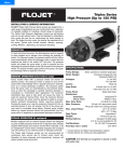
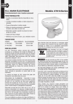
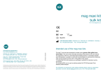
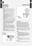
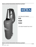
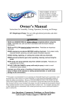
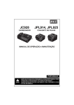
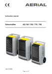
Menu
Model R3521 / 03521 Series
High Flow Triplex Pump
INSTALLATION & SERVICE INFORMATION
FLOJET Triplex High Flow Series pumps are designed for a wide
range of applications and are constructed from a selection of
materials suitable for handling a broad range of chemicals. The
Triplex High Flow pumps are self-priming and can run dry
without harm. They are intended for intermittent duty cycles but
can be run continuously for a short periods of time. The higher
the duty cycle, the shorter the expected life of the pump. Typical
uses include transfer, delivery, spraying, cooling, filtration,
dispensing, and pressure boosting.
OPERATION
Allow pump to prime with discharge line (or spray valve) open, to
avoid airlock. Built-in pressure switch will shut off pump
automatically when discharge valve is closed and will restart
pump when valve is opened. When pump runs out of liquid, it
will continue to operate. Running dry will not damage the pump.
Turn off manually.
SPECIFICATIONS
DEMAND OPERATION (intermittent duty)
Pump models fitted with a pressure switch are known as
demand pumps. The pressure switch is preset to shut off the
pump motor automatically when a specific pressure is reached,
such as in closed discharge conditions. The pressure switch
turns the pump motor on automatically as the pressure drops,
such as when the discharge is opened. Demand operation is
considered an “intermittent duty” application. The maximum
intermittent duty cycle is that which will cause the motor to
reach its maximum thermal limits. Once the maximum thermal
limit is reached, the motor must be allowed to settle to a lower
(ideally ambient) temperature, before resuming operation.
Running the pump at or near the maximum thermal limit for an
extended period of time will shorten the life of the pump and
may result in immediate pump failure. Demand pump models
feature an integral pressure switch that automatically turns the
pump off/on in response to open/closed discharge conditions.
BYPASS OPERATION (if equipped)
Models equipped with an external bypass system are designed
to pump at high pressures while at low or high flow rates. Models
equiped with bypass only must be turned off/on manually, or by
an independent control device. Models equipped with a bypass
only will continue to run until the power is manually turned off.
The Triplex High Pressure pumps are not recommended for
continuous duty service due to limited motor brush life.
Operation at lower pressures and temperatures, however, will
extend overall pump service life.
Pump Design:
Motor Design:
Voltages:
Pump Rating:
Amp Draw:
Pump Head:
Elastomers:
5
3
9
6
9
6
3 chamber diaphragm
Permanent magnet DC
12, 24 VDC
IP 54 (splash proof)
amps @ 10 psi for 12 VDC
amps @ 10 psi for 24 VDC
amps @ 10 psi for 12 VDC
amps @ 10 psi for 24 VDC
amps @ 40 psi for 12 VDC
amps @ 40 psi for 24 VDC
Polypropylene
SantopreneTM
Viton
Max. Flow Rate:
4 GPM (15.1 LPM)
Max. Pressure:
60 psi (4.1 bar) switch cutoff
50 psi (3.4 bar) max running pressure
Max. Liquid Temp:
40° F (4° C) Min*
140° F (60° C) Max*
Duty Cycle:
Intermittent**
Weight:
5.05 lbs ( 2.29 kg) max.
Wiring Options:
Standard 18 AWG leads
Port Size inlet / outlet:
3/4” (19 mm), 3/8” NPTF
Diaphragm
Check valves
* Consult factory for higher fluid temperature options
** Consult factory for continuous duty application
DIMENSIONAL DRAWINGS - inches (mm)
MOUNTING
WIRING
FLOJET Triplex 3521 Series pumps are self-priming. They may
Suggested wiring information is given as a reference only.
be located several feet from the tank, above or below the liquid
level (they are not submersible pumps).
PLUMBING
For best performance, flexible hose is recommended instead of
rigid piping at the pump. Flojet Triplex 3521 Series ports are a
push-in type retained by a “C” clip. To install the required ports
move “C” clip forward to front of pump. Do not install pump
such that plumbing causes excessive stress on either port.
It is essential that a 20 mesh (min.) strainer or filter be installed
in the tank or in the pump inlet line to keep large foreign
particles out of the system. The use of check valves in the
plumbing system may interfere with the priming ability of the
pump. Check valves, if used, must have cracking (opening)
pressure of no more than 2 PSI.
STEP 1
Determine the distance from the power source to the pump
and then double the measurement. Wire gauge installation is
determined on the entire run length, to the pump and back.
STEP 2
Connect to power supply lead (red (+)) to the positive (+)
terminal on the battery or through a properly installed
fuse/circuit breaker panel. Then run the length of wire to the
pump, connecting the red wire through a switch appropriately
rated to the pump’s current requirements.
STEP 3
Route the wire so as not to create hazards in operation of the
engine, movement of steering components or human traffic.
STEP 4
Connect the red lead to the red/orange lead on the pump.
WARNING
Risk of an electrical shock!
STEP 5
Connect the black lead from the pump to the ground or
negative power side (-) of the vessel.
HEAD-FLOW CURVE (12 & 24 VDC)
AMPS (A)
HEAD - PSI (bar)
STEP 6
Turn the system off when not in use for extended periods of
time or when the water supply tank is empty.
STEP 7
After installation, check voltage at the pump motor.
Voltage should be checked when pump is operating. Full
voltage must be available at the pump motor at all times for
proper pump operation and pump motor life.
flow
amp
IF YOU ARE NOT FAMILIAR WITH
APPLICABLE ELECTRICAL STANDARDS,
HAVE THE UNIT INSTALLED BY A
QUALIFIED ELECTRICIAN
FLOW RATE GPM (LPM)
DO NOT USE TO PUMP FLAMMABLE FLUIDS, GASOLINE, KEROSENE, OR ANY FUEL OIL
DO NOT USE PUMP IN AN EXPLOSIVE ENVIRONMENT
EXPLODED VIEW DRAWING
1
2
3
9
8
9
ITEM
4
5
6
7
10
DESCRIPTION
QUANTITY
PART NUMBER
1
Pressure Switch
1
02091060
2
Port Clips
1
21000407A
3
Valve Chamber Subassembly
1
20419015
4
Lower Housing Subassembly
1
20407021
5
??
1
??
6
??
1
??
7
long screws
1
??
8
short screws
1
??
9
??
1
??
DISASSEMBLE
REASSEMBLE
Pump Housing
(For numbers, refer to exploded view)
1. Disconnect power to the pump motor (5).
2. Remove the pressure switch cover (1) and remove the two
wire leads from the switch spade connectors.
3. Remove the six screws from the upper housing (7,8).
4. Remove the upper housing (6) from the check valve and
diaphragm/lower housing assemblies (3,4).
Check Valve Assembly
(To replace check valve only follow steps 1 through 6)
5. The check valve chamber and o-ring are located on the
diaphragm/lower housing assembly (3,4).
6. Remove the check valve chamber subassembly (3) from
the diaphragm/lower housing subassembly (pull the valve
chamber from the diaphragm) (3,4).
Diaphragm / Cam / Lower Housing Assembly
7. Remove the diaphragm/lower housing assembly (3,4) from
the motor front end bell adapter.
Motor Replacement
8. To replace the motor only, follow steps 1 and 2, then
disconnect 3 screws (7), and pull the pump head out.
Replace the motor with washer and gasket (9).
Pressure Switch Assembly
1. Install the switch diaphragm into upper housing (6).
Note: Check the old diaphragm for the material mark located
in the center of the new diaphragms. V is for VITON, and E
is for EPDM. Select the correct material for the installation.
2. Install the switch body over the diaphragm, align the screw
holes and install the two mounting screws.
3. Reinstall the two wires onto the spade connectors, then install
the switch cover and screw.
Check Valve Assembly
4. Install the o-ring into the o-ring groove located on the
discharge side of the check valve chamber assembly (3).
5. Install the check valve chamber assembly into the
diaphragm, thus aligning the check valve chamber with the
diaphragm seal walls (push in to secure to the diaphragm).
Upper Housing Assembly
6. With the check valve chamber sub assembly (3,4) installed
on the diaphragm, place the upper housing assembly (6)
onto the pre-assembled lower housing sub assembly (3,4).
7. Align the cam with the motor "D" shaft and motor list, then
slide the cam onto the motor shaft (lube the motor shaft
with a small amount of light grease).
8. Check the discharge location (see arrow on front of port) for
correct port orientation (discharge right is the standard position).
9. Install the six pump head screws (7,8) through the upper
housing (6), 3 screws (8) will engage to lower housing (4).
The other 3 screws (7) will go through the lower housing (5)
into the front end bell assembly aligning the three pins on
the front end bell with the 3 holes on the lower housing and
tighten securely.
Motor Assembly
10. Install the pump head by following steps 6 through 9.
PUMP TROUBLESHOOTING CHART
Failure to prime - motor operates, but no pump discharge
• Restricted intake or discharge line. Open all line valves,
check for "jammed" check valves, and clean clogged lines.
• Air leak in intake line.
• Punctured pump diaphragm.
• Defective pump check valves.
• Crack in pump housing.
• Debris in check valves.
• Missing or damaged o-ring of control valve chamber.
• Pinched/kinked hose.
• Damaged inlet or outlet check valve.
Motor fails to turn on
• Pump or equipment not plugged in electrically.
• Loose wiring connection.
• Pressure switch failure.
• Defective motor or rectifier.
• Frozen cam/bearing.
Pump fails to turn off after discharge valves are closed
• Depletion of available liquid supply.
• Punctured pump diaphragm.
• Discharge line leak.
• Defective pressure switch.
• Insufficient voltage to pump.
• Debris in check valves.
Low flow and pressure
• Defective check valves (most cases).
• Air leak at pump intake.
• Accumulation of debris inside pump and plumbing.
• Worn pump bearing (excessive noise).
• Punctured pump diaphragm.
• Defective rectifier or motor.
• Insufficient voltage to pump.
Pulsating flow - pump cycling on and off
• Restricted pump delivery. Check discharge lines, fittings,
valves and spray nozzles for clogging or undersizing.
AVAILABLE MODELS
PRODUCT WARRANTY
Visit www.flojet.com for a complete list model numbers.
FLOJET warrants this product to be free of defects in material
and/or workmanship for a period of one year after purchase by
the customer from FLOJET. During this one year warranty
period, FLOJET will, at its option and at no charge to the
customer, repair or replace this product if found defective. No
product will be accepted for return without a return material
authorization number. All return goods must be shipped with
transportation charges prepaid. This is only a summary of our
Limited Warranty. For a copy of our complete warranty, please
request Form No. 100-101.
PREVENTATIVE MAINTENANCE TIPS
If pumping a liquid other than water, the pump should be
flushed with water (if applicable) after each use. Sealers and
Teflon tape acting as a lubricant can cause cracked housings or
stripped threads due to over-tightening. Care should be used
when applying sealers; the tape may enter the pump, thus
inhibiting valve action and causing no prime or no shut-off
conditions. Failures due to foreign debris are not covered under
warranty.
Before freezing conditions occur, the pump must be liquid free
or winterized with proper anti-freezing chemicals. If mounting
the pump in an outdoor environment, the pump should be
shielded from water, dust, sunlight, and washdown spray. Do
not assume chemical compatibility. If the fluid is improperly
matched to the pump’s elastomers, the pump may fail to prime,
have low pressures, or the pressure switch may not shut off.
Contact your supplier for advice.
SERVICE KITS
Kits are readily available to repair standard Triplex High Pressure
Series pumps. To insure that the correct kits are received, the
model number and all name plate data must be included with
the order. Contact a FLOJET distributor to order the necessary
repair kits.
RETURN PROCEDURE
Prior to returning any product to FLOJET, call customer service
for an authorization number. This number must be written on the
outside of the shipping package. Place a note inside the
package with an explanation for return as well as the
authorization number. Include your name, address and phone
number. MSDS required.
www.flojet.com
U.S.A.
Flojet
666 E. Dyer Rd.
Santa Ana, CA 92705
Phone: 714.557.4700
Fax:
714.628.8478
UNITED KINGDOM
Flojet
Bingley Road, Hoddesdon
Hertfordshire EN11 OBU
Tel: +44 (0) 1992 450145
Fax: +44 (0) 1992 467132
Copyright 2006, ITT Industries
CANADA
Fluid Products Canada
55 Royal Road
Guelph, Ontario N1H 1T1
Tel: 519 821.1900
Fax: 519 821.2569
Printed in U.S.A.
JAPAN
NHK Jabsco Company Ltd.
3-21-10, Shin-Yokohama
Kohoku-Ku, Yokohama, 222
Tel: 045.475.8906
Fax: 045.475.8908
All Rights Reserved
GERMANY
Jabsco GmbH
Oststrasse 28
22840 Norderstedt
Tel: +49-40-53 53 73 -0
Fax: +49-40-53 53 73 -11
Form: 81000-417
ITALY
Jabsco Marine Italia
Via Tommaseo, 6
20059 Vimercate, Milano
Tel: +39 039 685 2323
Fax: +39 039 666 307
Rev. B 08/2006