1
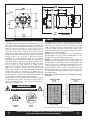
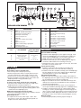
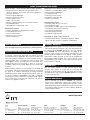
Menu
Triplex Series
High Pressure (Up to 150 PSI)
INSTALLATION & SERVICE INFORMATION
Triplex Series, High Pressure
FLOJET Triplex High Pressure Series pumps are designed for a
wide range of applications and are constructed from a selection
of materials suitable for handling a broad range of chemicals.
The Triplex High Pressure diaphragm pumps are self-priming
and can run dry without harm. They are intended for intermittent
duty cycles but can be run continuously for short periods of
time. The higher the duty cycle, the shorter the expected life of
the pump. Typical uses include transfer, delivery, spraying,
cooling, filtration, dispensing, and pressure boosting.
OPERATION
To start and prime the pump, the discharge line must be opened
to allow trapped air to escape, thus avoiding the potential of
airlock. For demand models, the pressure switch will shut off the
pump automatically when the discharge valve is closed and the
pressure has risen to the switch OFF set point. The pressure
switch will restart the pump when a valve is opened and the
discharge line pressure drops to the ON set point of the pressure
switch. For bypass models, apply power to the pump, and open
the discharge valve to expel air in the line.
SPECIFICATIONS
Pump Design:
Motor Design:
DEMAND OPERATION (intermittent duty)
Pump models fitted with a pressure switch are known as
demand pumps. The pressure switch is preset to shut off the
pump motor automatically when a specific pressure is reached,
such as in closed discharge conditions. The pressure switch
turns the pump motor on automatically as the pressure drops,
such as when the discharge is opened. Demand operation is
considered an “intermittent duty” application. The maximum
intermittent duty cycle is that which will cause the motor to
reach its maximum thermal limits. Once the maximum thermal
limit is reached, the motor must be allowed to settle to a lower
(ideally ambient) temperature, before resuming operation.
Running the pump at or near the maximum thermal limit for an
extended period of time will shorten the life of the pump and
may result in immediate pump failure. Demand pump models
feature an integral pressure switch that automatically turns the
pump off/on in response to open/closed discharge conditions.
BYPASS OPERATION (if equipped)
Models equipped with an external bypass system are designed
to pump at high pressures while at low or high flow rates. Models
equiped with bypass only must be turned off/on manually, or by
an independent control device. Models equipped with a bypass
only will continue to run until the power is manually turned off.
The Triplex High Pressure pumps are not recommended for
continuous duty service due to limited motor brush life.
Operation at lower pressures and temperatures, however, will
extend overall pump service life.
Voltages:
Cycles:
Amp Draw:
Pump Head:
Elastomers:
Motor operated 3 chamber diaphragm
Permanent magnet DC and
Rectified (PMDC) AC
12, 24 VDC
115, 230 VAC
50/60 Hz
9 amps max. for 12 VDC
0.95 amps max for 115 VAC
Glass filled Nylon
SantopreneTM
EPDM or Viton
Max. Flow Rate:
2.0 GPM (7.6 LPM)
Max. Pressure:
150 psi (10.3 bar) switch cutoff
140 psi (9.7 bar) max running pressure
Max. Liquid Temp:
40° F (4° C) Min*
160° F (71° C) Max
Duty Cycle:
Intermittent**
Weight:
7.6 lbs (3.5 kg) max.
Wiring Options:
Standard 18 AWG leads
6 ft. (2 m) cord available for AC
Certifications:
UL, CE, NSF Components
Port Size inlet / outlet:
3/8” NPTF
Diaphragm
Check valves
* Consult factory for higher fluid temperature options
** Consult factory for continuous duty application
CAUTION (115 Volt AC) UL recognition is based on tests
with water only
150 PSI Model
DIMENSIONAL DRAWINGS - inches (mm)
10.07
(256)
3.60
(91)
1.62
(41)
2.25
(57)
3.08
(78)
3/8" NPTF
3.67
(93)
1.9
(48)
3.18
(81)
9.44
(240)
3.93
(100)
100 PSI Model
MOUNTING
PLUMBING
FLOJET Triplex High Pressure Series pumps are self-priming.
Use flexible hose with the correct pressure rating that is
compatible with the fluid to be pumped. Tubing should be a
minimum of 3/8” (10 mm) ID and at least 20 inches (51 cm) in
length to avoid excess stress on the pump ports. Do not crimp
or kink the tubing. The pump head may be rotated in 120°
increments. Or reverse the flow (180°) by using other optional
lower housing to simplify plumbing.
FLOJET does not recommend the use of metal fittings;
standard plastic male and female threaded fittings can be
acquired at commercial plumbing supply stores.
FLOJET also distributes plastic barb fittings through our
distributors (form no. F100-001). The use of check valves in the
plumbing system could interfere with the priming ability of the
pump. If a check valve is installed in the plumbing, it must have
a cracking pressure of no more than 2 PSI (.14 bar). Use of a
minimum 40-mesh strainer or filter in the pump inlet line will
prevent foreign debris from entering the system. Failures due
to foreign debris entering the pump will not be covered under
the limited warranty.
Note: Inlet pressure must not exceed 30 PSI (2.1 bar)
maximum.
Vertical prime may vary depending on the fluid viscosity, suction
tube size, foot valve, and pump configuration. The pump should
be mounted in a dry and adequately ventilated area. If mounted
within an enclosure, provisions to cool the motor may be
necessary. When wiring electrically driven pumps, follow all
electrical and safety codes, as well as the most recent National
Electrical Code (NEC) and Occupational Safety and Health Act
(OSHA). Make certain the power source conforms to the pump
voltage, and be sure all power is disconnected before
installation. The pump should be wired into an individual
(dedicated) circuit, controlled with an UL/C-UL certified double
pole switch rated at or above the fuse ampere indicated on the
pump motor label. On 115-volt AC pumps, the black wire lead is
live or common, the white lead wire is neutral and the
green/yellow is ground. On 230-volt AC pumps the brown wire
lead is live or common, the blue wire is neutral and the
green/yellow is ground. On 12 and 24 volt pumps the red lead is
positive and should be connected to the battery plus (+)
terminal. The black lead is ground and should be connected to
the battery minus (-) terminal. Use T6 AWG wire minimum. Use
a fuse to protect the system wiring and components.
Improper duty cycle and/or rapid start/stop conditions caused
by undersized spray nozzles will cause the internal thermal
breaker (if equipped) to trip, or can cause premature motor
failure due to excessive heat.
HEAD-FLOW CURVE
100 psi
HEAD-FLOW CURVE
150 psi
FLOW RATE
110 (7.7)
5.5
100 (7.0)
5.0
90 (6.3)
4.5
4.0
70 (4.9)
3.5
60 (4.2)
3.0
50 (3.5)
2.5
40 (2.8)
2.0
30 (2.1)
1.5
20 (1.4)
1.0
0.5
10 (0.7)
.0
FLEXIBLE
HOSE
RIGID
PIPE
.5 (1.9)
1.0 (3.8)
1.5 (5.7)
2.0 (7.6)
170 (11.9)
160 (11.2)
150 (10.5)
140 (9.8)
130 (9.1)
120 (8.4)
110 (7.7)
100 (7.0)
90 (6.3)
80 (5.6)
70 (4.9)
60 (4.2)
50 (3.5)
40 (2.8)
30 (2.1)
20 (1.4)
10 (0.7)
0
.0
*FLOW RATE - GPM (LPM)
5.0
4.5
4.0
3.5
3.0
2.5
2.0
1.5
1.0
0.5
0.0
.5 (1.9)
1.0 (3.8)
1.5 (5.7)
FLOW RATE GPM (LPM)
* Some bypass models rated to 2.0 GPM (7.6 LPM)
DO NOT USE TO PUMP FLAMMABLE FLUIDS, GASOLINE, KEROSENE, OR ANY FUEL OIL
DO NOT USE PUMP IN AN EXPLOSIVE ENVIRONMENT
6.0
5.5
2.0 (7.6)
AMPS (A)
80 (5.6)
AMPS (A)
HEAD - PSI (bar)
Risk of an electrical shock!
6.0
HEAD - PSI (bar)
WARNING
FLOW RATE
120 (8.4)
A
B
C
17 16
15
14 13 12 11 10
9
8
7
6
5
4
3
2
18
22
19
23
D
20
E
1
21
24
EXPLODED VIEW DRAWING
ITEM
1
2
3
4
5
6
7
8
9
10
11
12
DESCRIPTION
Motor
Washer Ø .320 X Ø .620 X .040 ST
Screw #8-18 X 7/8 pan head (3)
Wobble plate subassembly
Lower housing, die cast
Diaphragm
Check valve chamber subassembly
O-ring
Upper housing, nylon
Backflow subassembly, polypropylene
Compression spring
Pulse dampener disc, nylon
KIT
KITS OFFERED
PARTS INCLUDED
ITEM
13
14
15
16
17
18
19
20
21
22
23
24
DESCRIPTION
Switch diaphragm, molded
Pressure switch
Screw #8-18 X 5/8 pan head (2)
Switch cover
Screw # 6-19 x .25 pan head (1)
Screw #10-32 x 1.5 pan head (3)
Screw #10-32 x 1.0 pan head (3)
Screw #4-20 X .52 pan head (2)
Bypass subassembly
Motor baseplate
Screw #10-32 x .38 pan head (2)
Grommets (4)
REASSEMBLE
(Bullet number)
A
B
C
D
P/N list
Pressure switch list
Check valve list
Lower housing subassy
1 thru 19
14, 15, 16, 17
7, 8
3, 4, 5, 6
E
Motor list
1, 2, 22, 23, 24
DISASSEMBLE
Pump Housing
(For numbers, refer to exploded view)
1. Disconnect power to the pump motor (1).
2. Remove the pressure switch cover (16) and remove the
two wire leads from the switch spade connectors (14).
3. Remove the six screws from the upper housing (18, 19).
4. Remove the upper housing (9) from the check valve and
diaphragm/lower housing assemblies (5,6).
Check Valve Assembly
(To replace check valve only follow steps 1 through 6)
5. The check valve chamber and o-ring are located on the
diaphragm/lower housing assembly (5, 6).
6. Remove the check valve chamber subassembly (7) from
the diaphragm/lower housing subassembly (pull the valve
chamber from the diaphragm) (5, 6).
Diaphragm / Cam / Lower Housing Assembly
7. Remove the diaphragm/lower housing assembly (5, 6) from
the motor front end bell adapter (1).
Motor Replacement
8. To replace the motor only, follow steps 1 and 2, then
disconnect 3 screws (18), and pull the pump head out.
Replace the motor with washer (2).
Pressure Switch Assembly
1. Install the switch diaphragm (13) into upper housing (9). Note:
Check the old diaphragm for the material mark located in the
center of the new diaphragms. V is for VITON, and E is for
EPDM. Select the correct material for the installation.
2. Install the switch body (14) over the diaphragm (13), align the
screw holes and install the two mounting screws (15).
3. Reinstall the two wires onto the spade connectors (14), then install
the switch cover and screw (16, 17).
Check Valve Assembly
4. Install the o-ring (8) into the o-ring groove located on the
discharge side of the check valve chamber assembly (7).
5. Install the check valve chamber assembly (7) into the diaphragm
(6), thus aligning the check valve chamber with the diaphragm
seal walls (push in to secure to the diaphragm).
Upper Housing Assembly
6. With the check valve chamber sub assembly (7-8) installed on
the diaphragm, place the upper housing assembly (9-21) onto the
pre-assembled lower housing sub assembly (D).
7. Align the cam with the motor "D" shaft and motor list (E), then
slide the cam onto the motor shaft (lube the motor shaft with a
small amount of light grease).
8. Check the discharge location (see arrow on front of port) for
correct port orientation (discharge right is the standard position).
9. Install the six pump head screws (18, 19) through the upper
housing (9), 3 screws (19) will engage to lower housing (5). The
other 3 screws (18) will go through the lower housing (5) into the
front end bell assembly aligning the three pins on the front end
bell with the 3 holes on the lower housing and tighten securely.
Motor Assembly
10. Install the pump head by following steps 6 through 9.
PUMP TROUBLESHOOTING CHART
Failure to prime - motor operates, but no pump discharge
• Restricted intake or discharge line. Open all line valves,
check for "jammed" check valves, and clean clogged lines.
• Air leak in intake line.
• Punctured pump diaphragm.
• Defective pump check valves.
• Crack in pump housing.
• Debris in check valves.
• Missing or damaged o-ring of control valve chamber.
• Pinched/kinked hose.
• Damaged inlet or outlet check valve.
Motor fails to turn on
• Pump or equipment not plugged in electrically.
• Loose wiring connection.
• Pressure switch failure.
• Defective motor or rectifier.
• Frozen cam/bearing.
Pump fails to turn off after discharge valves are closed
• Depletion of available liquid supply.
• Punctured pump diaphragm.
• Discharge line leak.
• Defective pressure switch.
• Insufficient voltage to pump.
• Debris in check valves.
Low flow and pressure
• Defective check valves (most cases).
• Air leak at pump intake.
• Accumulation of debris inside pump and plumbing.
• Worn pump bearing (excessive noise).
• Punctured pump diaphragm.
• Defective rectifier or motor.
• Insufficient voltage to pump.
Pulsating flow - pump cycling on and off
• Restricted pump delivery. Check discharge lines, fittings,
valves and spray nozzles for clogging or undersizing.
AVAILABLE MODELS
PRODUCT WARRANTY
Visit www.flojet.com for a complete list model numbers.
FLOJET warrants this product to be free of defects in material
and/or workmanship for a period of one year after purchase by
the customer from FLOJET. During this one year warranty
period, FLOJET will, at its option and at no charge to the
customer, repair or replace this product if found defective. No
product will be accepted for return without a return material
authorization number. All return goods must be shipped with
transportation charges prepaid. This is only a summary of our
Limited Warranty. For a copy of our complete warranty, please
request Form No. 100-101.
PREVENTATIVE MAINTENANCE TIPS
If pumping a liquid other than water, the pump should be
flushed with water (if applicable) after each use. Sealers and
Teflon tape acting as a lubricant can cause cracked housings or
stripped threads due to over-tightening. Care should be used
when applying sealers; the tape may enter the pump, thus
inhibiting valve action and causing no prime or no shut-off
conditions. Failures due to foreign debris are not covered under
warranty.
Before freezing conditions occur, the pump must be liquid free
or winterized with proper anti-freezing chemicals. If mounting
the pump in an outdoor environment, the pump should be
shielded from water, dust, sunlight, and washdown spray. Do
not assume chemical compatibility. If the fluid is improperly
matched to the pump’s elastomers, the pump may fail to prime,
have low pressures, or the pressure switch may not shut off.
Contact your supplier for advice.
SERVICE KITS
Kits are readily available to repair standard Triplex High
Pressure Series pumps. To insure that the correct kits are
received, the model number and all name plate data must be
included with the order. Contact a FLOJET distributor to order
the necessary repair kits.
RETURN PROCEDURE
Prior to returning any product to FLOJET, call customer
service for an authorization number. This number must be
written on the outside of the shipping package. Place a note
inside the package with an explanation for return as well as the
authorization number. Include your name, address and phone
number. MSDS required.
www.flojet.com
U.S.A.
Flojet
20 Icon
Foothill Ranch, CA 92610
Tel: 949.859.4945
Fax: 949.859.1153
UNITED KINGDOM
Flojet
Bingley Road, Hoddesdon
Hertfordshire EN11 OBU
Tel: +44 (0) 1992 450145
Fax: +44 (0) 1992 467132
Copyright 2006, ITT Industries
CANADA
Fluid Products Canada
55 Royal Road
Guelph, Ontario N1H 1T1
Tel: 519.821.1900
Fax: 519.821.2569
Printed in U.S.A.
JAPAN
NHK Jabsco Company Ltd.
3-21-10, Shin-Yokohama
Kohoku-Ku, Yokohama, 222-0033
Tel: 045.475.8906
Fax: 045.477.1162
All Rights Reserved
GERMANY
Jabsco GmbH
Oststrasse 28
22840 Norderstedt
Tel: +49-40-53 53 73 -0
Fax: +49-40-53 53 73 -11
Form: 81000-409
ITALY
Jabsco Marine Italia
Via Tommaseo, 6
20059 Vimercate, Milano
Tel: +39 039 685 2323
Fax: +39 039 666 307
Rev. A 02/2006