1
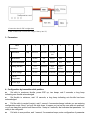
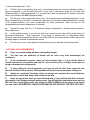
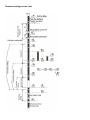
Turnigy DP 3A 1S 1g Brushless Speed Controller User Manual Hobbyking # 7184 1. Functional features: Supply voltage: 2.9V~4.2V (1 cell Li-poly Battery). Working continuous current: 2.5A; 30+ sec on 3A load; Instantaneous peak current: 3.5A. Motor rotation can be changed by switching the connection of any two of the three wires. Advanced heuristic algorithm to meet the requirements of motors with different numbers of magnetic poles. Secure arming Once powered, the motor will not arm unless the throttle position of the remote controller is at minimum. Lost signal protection If the signal received is bad or unstable, power to the motor will be cut off gradually by the protection program after 2 seconds. If the signal is restored within 2 seconds, the ESC will resume previous operation. High temperature protection A high temperature protection circuit will gradually limit output power . Abnormal voltage protection When the input voltage is lower than 2.9V or higher than 4.4v, the ESC runs a protection program. Li-Battery protection Motor power will be cut off gradually when the voltage on the battery is found lower than the setting value. Halted run protection If the propeller becomes locked-up, the max power output will be limited to 36%. Configurable Parameters Internal parameters may be configured with the Configuration card or by stick position on the transmitter. 2. Connection illustration (Connection chart for normal ESC usage) (Connection chart for ESC configuration) (UBEC module used to convert the voltage of battery into 5V) 3. Parameters Value 0 1 2 3 4 skip Fast start Soft start Very soft start Disable Soft Normal Hard Faster Fast Normal Slow Low advance Standard High advance Higher advance Disable 2.9V/Cell 3.0V/Cell 3.1V/Cell 80ºC 90ºC 100ºC 110ºC Soft cut-off Cut-off 5 6 Parameters 1 Start Mode 2 Break Force 3 Acceleration Mode 4 Timing Advance 5 Cut-off Voltage 6 Cut-off Temperature 7 Protect Type skip skip skip skip skip skip Slower 3.2V/Cell 3.3V/Cell 4. Configuration by transmitter stick position: ● Set stick to maximum throttle, power ESC up, two beeps, wait 3 seconds, a long beep indicating max throttle acknowledged. Set throttle to minimum, wait 1.5 seconds, a long beep indicating min throttle has been acknowledged. ● ● Pull the stick to neutral (center), wait 1 second, 4 successive beeps indicate you are entering configuration mode. Now if you pull the stick down, it means you just set the max and min positions, or you can keep this position and there will be 1 beep in 2 seconds, that indicates that parameter 1 is ready to be configured. ● Pull stick to max position, wait 1 second, 2 successive beeps, enter configuration of parameter 1, and now set parameter 1 as 0. Pull the stick to min position from max, 2 successive beeps for one time indicating adding 1 value to parameter 1; pull the stick from min to max, also 2 successive beeps for one time, also indicating adding 1 value to parameter 1. If you add value when the parameter is already at the max value, your operation will NOT change anything. ● ● Pull the stick to the neutral from max or min, 3 successive beeps indicating parameter 1 is set. Keep this position for 2 seconds, 2 successive beeps every 2 seconds indicating parameter 2 is ready to be configured.(Before you enter configuration for other parameters, there will also be the corresponding successive beeps every 2 seconds) ● Repeat the steps from 4 to 6 to finish the setting of parameter 2, and the same process for other parameters. ● In the setting process, if you pull the stick from neutral to min, there will be some beeps (3 successive beeps plus 1 short beep plus 1 long beep) to indicate end of configuration mode. However, when all the parameters are set, even if the stick is in the neutral position, there will also be the same beeps to indicate all parameters are set. ● Pull the stick to min, a long beep will indicate that you have entered normal flying mode. CAUTION! (VITAL INFORMATION) A) Every successful setting will have confirmation beep(s). B) The max and min positions of throttle will be reset every time parameter(s) are configured. C) In the configuration process, when you have finished step 3, if you pull the stick to neutral from max or min position and wait for 1 second at any time, it always means you are trying to terminate the configuration. D) To skip setting of current parameter, you have to pull the stick from neutral to max position and then back to neutral. That operation will set the current parameter setting to 0. E) Values are consistent. Parameter values are always even numbers if you pull stick from max position to neutral and always odd numbers from min. F) In the set up process, when you have finished step 3, if you pull the stick from neutral to min position it will always terminate setting mode. You will hear the termination beeps and the ESC will enter normal flying mode. You need to be VERY CAREFUL as the motor is armed and can now rotate! SUGGESTION: ALWAYS PROGRAM THE ESC WITHOUT THE PROP IN PLACE. 5. Parameter setting chart Command legends Parameters settings chart Parameter setting process chart 6. Abnormal Condition Protection Notes The Protection program will be triggered and the ESC will beep alert(s) tones when an abnormal condition is found: Lost signal protection: beep once a second High temperature protection: 3 beeps once a second Abnormal voltages, battery protection: 1 beep every 2 seconds Stick NOT on min throttle position when powered up: beep once a second Caution: When the protection program is triggered, the motor will cut off gradually and then the program will check throttle position; if it’s on Min position, the ESC will go into Standby status.