1
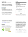
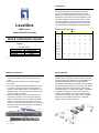
Introduction LevelOne Secure WLAN Controller is the most advanced yet simple deployment and cost-effective wireless solution; it is an ideal security solution for small to larger-scale WLAN deployments, including campuses, enterprises, hotels and Telco hotspot application. This Controller integrates “secure access control”, “visitor account provisioning”, “flexible accounting and billing”, and “centralized WLAN management” into one box to provide simplified manageability and instant mobility. LevelOne Product Comparison Table WHG series Secure WLAN Controller Capacity WHG-311 WHG-315 WHG-401 WHG-505 WHG-515 Size 13" 19”(1U) 19”(1U) 19”(1U) 19”(1U) WAN Quick Installation Guide English Default Settings IP (Mgmt Access*) IP (LAN Access) Username Password 172.30.0.1 192.168.1.254 admin admin * Mgmt port is only available on certain models 2 x GbE 2 x GbE 2 x GbE 2 x GbE 2 x GbE WHG-707 19”(1U) 2 x GbE, 2 x SFP 4 x GbE, LAN 8 x GbE 8 x GbE 2 x GbE 2 x GbE 4 x GbE Management n/a n/a Yes Yes Yes n/a Account 3000 4000 5000 6000 10000 15000 2 x SFP Managed AP 30 50 150 200 250 500 Monitored IP 100 100 200 200 250 500 Service Zones 9 9 9 9 9 9 User Groups 8 8 16 24 24 24 User Policies Global + 12 Global +12 Global + 24 Global + 40 Global + 40 Global + 40 Local VPN 80 120 240 500 600 1000 Concurrent User 100 150 300 500 800 1500 V1.4 2 1 Hardware Installation Getting Started Please follow the following steps to install WHG 1. Connect the power to the power socket on the rear panel. 2. The Power LED should be on to indicate a proper connection. 3. Connect an Ethernet cable to the WAN1 Port on the front panel. Connect the other end of the Ethernet cable to a xDSL/cable modem, or a switch/hub of an internal network. The LED of this port should be on to indicate a proper connection. 4. Connect an Ethernet cable to any LAN Port on the front panel. Connect the other end of the Ethernet cable to an administrator PC to configure the WHG system, an AP for extending wireless coverage, a switch for connecting more wired clients, or a client PC. The LED of this LAN port should be on to indicate a proper connection. xDSL Modem The WHG Controller is capable of managing user authentication, authorization and accounting. The user account information is stored in the local database or a specified external database server (AAA Server). It features an external payment gateway with integrated user authentication, allowing users to easily pay the fee and enjoy the Internet service by using credit cards through Authorize.net, PayPal, SecurePay, or WorldPay. The WHG introduces the concept of Service Zones multiple virtual networks, each with its own definable Access Control profiles. This is very useful for hotspot owners to provide different customers or staff with different levels of network services. Internet Managed Switch 3 4 Web Management Interface The default user login page will then appear in the browser. The WHG supports web-based configuration. Upon the completion of hardware installation, it can be configured via web browsers with JavaScript enabled such as Internet Explorer version 6.0 and above or Firefox. 1. To access the Web Management Interface, connect a PC to any LAN Port. Make sure you have set DHCP in TCP/IP of your PC to get an IP address automatically. Start your Browser to access the Web Management Interface 2. Enter the gateway IP address of the WHG in the address field of your Browser. The default gateway IP address is https://192.168.1.254 (“https” is used for a secured connection). 3. The administrator login page will appear. Enter “admin” as the default username, and “admin” as the default password in the User Name and Password fields respectively. Click Enter to log in. 4. After a successful login, a System Home page will appear on the screen. From the Home Page, network administrator can navigate to “Setup Wizard”, “Quick Links”, “System Overview” and “Main Menu”. 5 Note: On first time use, if you connect to the WHG without a trusted SSL certificate, the Browser will treat the WHG as an untrusted website and throw a “Certificate Error”. This can be safely ignored. Just press “Continue to this website” to continue. If you can’t get to the login screen, the reasons may be: 1) The PC is configured incorrectly so that the PC can’t obtain the IP address automatically from the LAN port 2) The IP address and the default gateway are not under the same network segment. In that case configure your PC to have a fixed IP address such as 192.168.1.xxx and try again. 6 Setup Wizard WHG provides a Setup Wizard for quick configuration. Click on the Setup Wizard button to start the configuration process. Step 1: General Enter a new password in the New Password field, and re-enter it again in the Verify Password field (a maximum of 20 characters and no spaces allowed in between). Select an appropriate time zone from the Time Zone drop-down list box to set up the system time. Click Next to continue. Note For security concern, it is strongly recommended to change the administrator password 7 Step 2: WAN1 Interface For setting up both wired WAN and wireless LAN functions: Select a proper type of Internet connection for WAN1 interface from the following three available connections: Static, Dynamic, or PPPoE. Your ISP or network administrator can advise on the connection type available to you. Above depicts an example for Dynamic. Click Next to continue. Step 3: Local User Account (Optional) New local accounts can be created and added into the database via this optional function. If local user accounts are not required, click Skip to go directly to Step 4. However, it is recommended to create at least one local user account in order to verify the system‘s readiness upon completion of this Setup Wizard. Enter the Username (e.g. “testuser) and Password (e.g. “testuser”) to create a new local account. 8 Click Next to continue. More local accounts can be added by clicking the Back button in Step 4. Step 4: Confirm and Restart Click Finish to save current settings and restart the system. A confirmation dialog box will then appear. Click OK to continue. A Confirm and Restart message will appear on the screen during the restarting process. Please do not interrupt the system until the Administrator Login Page appears. User Login To verify whether the configuration of the new local user account(s) created via the Setup Wizard has been completed successfully: 1. Connect a client device (e.g. laptop, PC) to any LAN Port of WHG. The device will obtain an IP address automatically via DHCP. 2. Open a web browser on a client device, access any URL, and then the default User Login Page will appear. 3. Enter the Username and Password of a local user account previously generated via Setup Wizard (e.g. “testuser@local” as the Username and “testuser” as the Password); then Click Login. Note: The system is trying to locate a DNS server at this stage. Therefore, a longer startup time is required if the configured DNS cannot be found. When the following Administrator Login Page appears, it means the restart process is now completed. Note: 1. WHG supports multiple authentication options including built-in local user database and external authentication database (e.g. RADIUS). The system will automatically identify which authentication option is used from the full username entered. 9 2. The format of a full (valid) username is userid@postfix, where “userid” is the user ID and “postfix” is the name of the selected authentication option. 3. Exception: The postfix can be omitted only when the default authentication option is used. For example, “LOCAL” is the default authentication option at this system; therefore, you may enter either “testuser” or “testuser@local” in the Username field. Congratulations! The Login Success Page will appear after a client has successfully logged into WHG and has been authenticated by the system. The appearance of Login Success Page means that WHG has been installed and configured properly. 11 10 Service Zone LevelOne Service Zones are virtual machines that has its’ own network interface, DHCP server, authentication configuration, user pages as well as security and user policy settings. By associating a unique VLAN Tag and SSID with a Service Zone, administrators can separate wired network and wireless network into different logical networks isolated from one another. Users attempting to access the resources within the Service Zone will be controlled based on the access control profile of the Service Zone, such as authentication, security feature, wireless encryption method, traffic control, and etc. There are nine Service Zone profiles in total, Default Service Zone and Service Zones 1 ~ 8. 12 Simple network environment Multiple subnet network environment For most simple internal network, there are just two subnets for example. Using Port-Based model is an easy and better way. In Port-Based mode (configurable in Port Location Mapping tab page), each LAN port can only serve traffic from one Service Zone. An example of network application diagram is shown as below: one Service Zone for Employees and one for Guests. On the other hand, if the internal network is a multiple subnets network environment, Tag-Based model will satisfy to your demands. In Tag-Based mode, each LAN port will serve traffics from different Service Zones; a VLAN switch or VLAN AP is required to take care of the VLAN tags carried within the message frames. An example of network application diagram is shown as below: more than two Service Zones for different departments. 13 14 Go to System => Service Zones => Service Zone Configuration Additional to hide the IP address of a Service Zone’s network interface and to some degree, provide protection from possible attacks from LAN clients. DHCP Server: From the drop down menu, DHCP server for this particular service zone may be Disabled, Enabled or Relayed. Please note that when “Enable DHCP Relay” is enabled, fill in the IP address of the external DHCP Server, and the IP address of clients will be assigned by an external DHCP server. The system will only relay DHCP information from the external DHCP server to downstream clients of this service zone. Please note that Controller should be in the same subnet as the DHCP server. Service Zone Status: Each service zone can be enabled or disabled except for the default service zone. Service Zone Name: The name of service zone could be input here. Network Interface: o VLAN Tag (Tag Base Only): The VLAN tag number that is mapped to the Service Zone. o Inter LAN Port Isolation (Port Base Only): Select Enable, Auth Required or Disable. When the o When the option is “Enabled”, clients under different LAN ports cannot ping each other. When the option is “Disabled”, clients under different LAN ports can ping each other. When the option is “Auth Required”, clients under different LAN ports cannot ping each other unless both of them has successfully authenticated. o Operation Mode: Contains NAT mode and Router mode. When NAT mode is chosen, service zone runs in NAT mode o When the NAT mode is chosen, Service Zone runs in NAT mode. When Router mode is chosen, Service Zone runs in Router mode. o IP Address: The IP Address of this service zone. o Subnet Mask: The subnet Mask of this service zone. o IPv6 Settings: The IPv6 Address and configuration of this service zone (when IPv6 is enabled). o Network Alias List: Administrator may optionally set many alias network segments for a service zone. This feature can allow a single service zone to be seen as many service zones. 15 16 AP Management Setting up APs The Controller detects supported APs and push configuration to batch APs at the same time. Features are included: AP Discovery Add AP Manually Apply Settings Reboot, Enable, Disable and Remove the AP Firmware upgrade and management The system supports up to three templates which contains set of pre-defined settings of AP. The administrator can configure the setting together in the template instead of logging the AP management interface to set the configurations one by one. Select the AP type (if available) and one of the three available templates, and then click Edit to have the Template Editing page. The basic rules for setting up managed APs are: 1. Configure AP Template: includes Subnet Mask, Default Gateway IP, Time Zone, SSID Broadcast, WiFi Frequency, etc. 2. Discover APs 3. Apply the AP Template to discovered APs Go to Access Point => Enter Local Area AP Management => Templates => Select Template1 => Edit => Configure 17 18 AP Discovery Discovery Results After AP template configuration is complete, use this function to detect and scan for all of the APs connected under the managed network. Note that in Local Area AP Management the WHG Controller can only manage APs that are connected to its LAN ports. Therefore, the AP discovery function is for adding locally connected APs to its management list. The administrator must know the local IP addresses of the APs he/she wishes to discover. Or the alternative is to reset the AP to default setting for discovery. The newly discovered APs will be listed here. After clicking Add, the current management page is directed to AP List, where the newly added APs will show up in the AP List with a status of “configuring”. It may take a few minutes to complete the process until showing “online” status. Go to Access Point => Enter Local Area AP Management => Discovery Once all APs are showed “online” status, the AP configuration is complete. You can also perform other things under AP Management section such as “Firmware Upgrade”, “Add AP Manually” or Apply different “Template” etc. For more details, please refer to User Manual. 19 20 Note: For the optional ticket printer, it’s required to be added & configured at [Terminal Server] before it can operate with Controller. Create Billing Plan WHG has built-in billing plan for temporary accounts for guest usage with free or paid wireless Internet access in the hotspot environment. In order to set billing rules for on-demand users, we need to create at least one billing plan. Go to Billing Plans, click [Edit] from Plan 1, Go to Main Menu => Users => Authentication => On-demand User Under [General Settings] contains generated on-demand users and all accounts related information such as Currency, Group Name, ESSID, etc. Select [Account Type] based by time or data usage, and then define all necessary settings to meet the requirement 21 22 Create On-demand User Account Print On-demand Account from Ticket Printer After at least one plan is enabled, the administrator can generate on-demand user accounts here. Click on the Create button of the desired plan and an on-demand user account will be created. After the account is created, you can print the ticket with all of the necessary user’s information, including the username and password. Terminal Server and at least one Billing Plan must be created before it can operate properly. The Ticket Printer kit is optional accessory for the WHG Controller. Main Menu => Users => Authentication => On-demand User : General Settings => Terminal Server Billing Plans Switch PRT-1000 DAS-1000 WHG Controller Now operator can print out on-demand user ticket easily by pressing [Enter] key. Also change different pre-defined billing plan by pressing [Up] and [Down] keys accordingly Note: Please refer to User Manual for more details 23 24