1
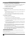
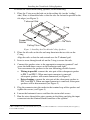
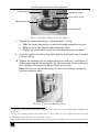
Kramer Electronics, Ltd.
USER MANUAL
Models:
SPK-CC688, Closed-back Ceiling Speakers
SPK-CC448, Closed-back Ceiling Speakers
SPK-CC444, Closed-back Ceiling Speakers
SPK-CC348F, Closed-back Ceiling Speakers
Contents
Contents
1
2
3
4
5
5.1
5.2
5.3
6
Introduction
Getting Started
Overview
Your Closed-back Ceiling Speakers
Installing the Closed-back Ceiling Speakers
Choosing the Best Location
Cutting the Ceiling Tile
Painting the Speaker
Technical Specifications
1
1
2
3
5
5
5
8
9
Figures
Figure 1: Closed-back Ceiling Speaker
Figure 2: Closed-back Ceiling Speaker Schematic Diagram
Figure 3: Installing the Closed-back Ceiling Speakers
Figure 4: Plugging and Securing the Cables
Figure 5: Tighten the Mounting Tabs
Figure 6: Adjust Tap Selector (for the SPK-CC688)
3
4
6
7
7
8
Tables
Table 1: Closed-back Ceiling Speakers – Definition
Table 2: Closed-back Ceiling Speakers Hardware Items
Table 3: Ceiling Mounting Kit Items
Table 4: Technical Specifications of the SPK-CC688
Table 5: Technical Specifications of the SPK-CC448 and the SPK-CC444
Table 6: Technical Specifications of the SPK-CC348F
2
3
4
9
9
10
i
Introduction
1
Introduction
Welcome to Kramer Electronics! Since 1981, Kramer Electronics has been
providing a world of unique, creative, and affordable solutions to the vast
range of problems that confront the video, audio, presentation, and
broadcasting professional on a daily basis. In recent years, we have
redesigned and upgraded most of our line, making the best even better! Our
500-plus different models now appear in eight groups1 that are clearly defined
by function.
Congratulations on purchasing your Kramer Closed-back Ceiling Speakers,
available in four models: SPK-CC688, SPK-CC448, SPK-CC444 and/or
SPK-CC348F, which are ideal for:
Home theater sound systems
Multimedia systems
The package includes the following items:
Closed-back Ceiling Speakers SPK-CC688, and/or SPK-CC448 and/or
SPK-CC444 and/or SPK-CC348F
Mounting kit
This user manual2
2
Getting Started
We recommend that you:
Unpack the equipment carefully and save the original box and packaging
materials for possible future shipment
Review the contents of this user manual
Use Kramer high performance cables3
1 GROUP 1: Distribution Amplifiers; GROUP 2: Video and Audio Switchers, Matrix Switchers and Controllers; GROUP 3:
Video, Audio, VGA/XGA Processors; GROUP 4: Interfaces and Sync Processors; GROUP 5: Twisted Pair Interfaces;
GROUP 6: Accessories and Rack Adapters; GROUP 7: Scan Converters and Scalers; and GROUP 8: Cables and Connectors
2 Download up-to-date Kramer user manuals from the Internet at this URL: http://www.kramerelectronics.com
3 The complete list of Kramer cables is on our Web site at http://www.kramerelectronics.com
1
Overview
3
Overview
The Closed-back Ceiling Speakers include a pair of high performance closed
back speakers that can be mounted on the ceiling, as well as a ceiling
mounting kit for safely securing the speakers to the ceiling. Table 1 defines
the closed-back ceiling speakers:
Table 1: Closed-back Ceiling Speakers – Definition
Name
Diameter [“]
SPK-CC688
SPK-CC448
SPK-CC444
SPK-CC348F
6.5
4
4
3
Resistance [ ]
8
8
4
8
Closed-back Depth [“]
8
4
4
4
To achieve the best performance:
Connect only good quality connection cables1, thus avoiding interference,
deterioration in signal quality due to poor matching, and elevated noiselevels (often associated with low quality cables)
Avoid interference from neighboring electrical appliances and position your
Kramer Closed-back Ceiling Speakers away from moisture, excessive
sunlight and dust
1 Such as the Kramer BC-2S cable
2
KRAMER: SIMPLE CREATIVE TECHNOLOGY
Your Closed-back Ceiling Speakers
4
Your Closed-back Ceiling Speakers
Figure 1 and Table 2 define the closed-back ceiling speakers:
Figure 1: Closed-back Ceiling Speaker
Table 2: Closed-back Ceiling Speakers Hardware Items
Description
A pair of
ceiling
speakers
(one shown)
Two grilles
(one shown)
Cutout
template
3
Your Closed-back Ceiling Speakers
Table 3 defines the ceiling mounting kit items
Table 3: Ceiling Mounting Kit Items
Four
support
ring screws
Two
ceiling
support
rings
(C-ring) –
one shown
Two pairs of
tile rails – one
of a pair
shown
Each closed-back ceiling speaker is supported by a C-ring and two tile rails1.
When mounting onto the ceiling tiles2, use both supports. When mounting onto
a sheetrock ceiling, the C-ring alone is used to reinforce the ceiling material.
Figure 2 shows a schematic diagram of the closed-back ceiling speaker:
Figure 2: Closed-back Ceiling Speaker Schematic Diagram
1 The tile rails prevent the speakers from falling if the tile itself comes out or falls apart, as their ends catch onto the T-grid
2 Be sure that the tiles can support the speaker. Smaller sized tiles or fiberglass-type tiles cannot support the weight of the
speakers. When this is the case, the speakers will need additional support
4
KRAMER: SIMPLE CREATIVE TECHNOLOGY
Installing the Closed-back Ceiling Speakers
5
Installing the Closed-back Ceiling Speakers
This section explains how to install the closed-back ceiling speakers, that is:
Choosing the best place to locate your speakers (see section 5.1)
Cutting the ceiling tile (see section 5.2)
Painting the speakers (see section 5.3)
5.1 Choosing the Best Location
Ideally, locate the speakers above the main listening area. Before doing so, be
sure that:
The desired location is free of obstructions, such as electrical piping, AC
ducts or water lines, and so on
There is enough space behind the mounting surface for the speakers
Rear side of the speaker is not blocked by wall studs or other objects
5.2 Cutting the Ceiling Tile
To cut the ceiling tile, do the following:
1. Remove the circle in the supplied cardboard template1.
2. Mark the opening in the correct location by tracing the hole in the template.
3. Cut out the hole according to the template or with a circular cutter set to
the appropriate cutout size2.
4. Route the wiring from the amplifier to the speakers’ cutout holes, taking
care not to place them next to electrical wires or at least at a distance of
about two feet from an AC line3.
If you are mounting the speakers onto a ceiling tile, remove the ceiling tiles
where you plan to install the speakers. Use the template to trace and then
cutout the speaker hole over an empty box.
The closed-back ceiling speakers are supported by the ceiling mounting kit
(two C-rings and two pairs of tile rails4). When mounting onto the ceiling
tiles5, use both supports. When mounting onto a sheetrock ceiling, the C-ring
alone is used to reinforce the ceiling material.
1 Keep this circular piece of cardboard for later use as a mask, as you may want to paint the speakers (see section 5.3)
2 Initially, you can cut a smaller area inside the marked hole just to be sure that the space above the speakers is clear
3 Do not nail or staple the speaker wires
4 The tile rails prevent the speakers from falling if the tile itself comes out or falls apart, as their ends catch onto the T-grid
5 Be sure that the tiles can support the speaker. Smaller sized tiles or fiberglass-type tiles cannot support the weight of the
speakers. When this is the case, the speakers will need additional support
5
Installing the Closed-back Ceiling Speakers
To install the closed-back ceiling speakers, do the following:
1. Place the C-ring over the hole cut in the ceiling tile (on the “ceiling”
side). Place it around the hole so that the tabs are located in parallel to the
tile edges (see Figure 3).
T-channel Grid
C-ring
Support Ring
Screws
Ceiling Tile
Tile Rails
Figure 3: Installing the Closed-back Ceiling Speakers
2. Place the tile rails on the tile and snap them into the two tabs on the
C-ring.
Align the rails so that the ends extend over the T-channel grid.
3. Insert a screw through each tab on the C-ring to secure the rails.
4. Connect the speaker wires to the appropriate connector terminals1 and
screw the hold-down screws on the connector until tight2.
You can connect the speakers in the two following possible layouts:
Wiring in parallel: connect the wire pair of the subsequent speaker
to PIN 2 and PIN 3. When one input connector is removed,
subsequent speakers will remain connected (see Figure 2)
Daisy-chaining: connect the wire pair of the subsequent speaker to
PIN 1 and PIN 4. When one input connector is removed, subsequent
speakers will be disconnected (see Figure 2)
5. Plug the connector into the socket in the terminal cup of the speaker and
tighten the screws (see Figure 4).
6. Loosen the horizontal screws and then the strain relief screws.
7. Run the wires through the wires opening in the fitting and plug the input
connector into the terminal block connector of the speaker.
1 PIN 1 and PIN 2 are connected internally and are positive (+). PIN 3 and PIN 4 are connected internally and are negative (-)
2 Use a small screwdriver
6
KRAMER: SIMPLE CREATIVE TECHNOLOGY
Installing the Closed-back Ceiling Speakers
Wires opening
Horizontal screw
Strain relief screw
Hold down screw
Terminal block
Figure 4: Plugging and Securing the Cables
8. Tighten the strain relief fitting, if plenum cable1 is used:
Slide the wiring through the strain relief on the terminal cover plate
Hold the strain relief fitting tight around the cable
Tighten the strain relief screws first and then the horizontal screw2
9. Push the speaker into the ceiling hole until the front baffle rim is leveled
with the ceiling.
10. Tighten the mounting tabs by turning the screw clockwise3 (see Figure 5).
When tightening the mounting tabs, the tabs automatically turn outward,
thus clamping the speaker to the wall from its rear side.
Note: Do not over-tighten the screws. It may cause damage to both the
speakers and the surface.
Figure 5: Tighten the Mounting Tabs
1 If other types of cables are used, an alternate conduit fitting can be used by removing the existing fitting and replacing with
an alternate one
2 In cases of an insulated speaker wire and plenum cable, it is often possible to provide acceptable strain relief force simply
by tightening the strain relief screws onto the terminal cover plate
3 The first quarter turn, rotates the tab outwards, and the following turns the tabs tighten to the rear side of the ceiling surface
7
Installing the Closed-back Ceiling Speakers
11. If required, you can further secure the speaker by connecting the speaker
support ring to an independent secure anchor point.
12. Adjust each speaker to the appropriate tap setting1 before installing the
grille2 (see Figure 6).
Figure 6: Adjust Tap Selector (for the SPK-CC688)
13. Install the grilles to the speakers:
Push the grille fastener into the hole in front of the baffle
Press the grille into place until the front of the grille is flush with the
rim of the baffle
Check that the grille is securely seated3
5.3 Painting the Speaker
You can paint the speakers before or after the speaker is installed.
When painting before installation:
Clean the rim and grille with mineral spirits or other light solvent that is
unlikely to damage the surface
Spray with color by holding the spray can at an angle of 45
Note: When spraying the grille, take care not to clog the holes in the grille
as this will greatly reduce the sound quality of the speakers
1 The tap selector has different values depending on the model. For example, Figure 6 shows the Tap Selector for the
SPK-CC688
2 In addition to the 8
setting, the power taps are 30W, 15W, 7.5W and 3.7W at both 70.7V and 100V, with a 1.8W tap for
70.7V only
3 To remove the grille, insert two bent paper clips into the holes in the grille and carefully pull it down. Repeat this around the
perimeter of the grille until it is completely removed
8
KRAMER: SIMPLE CREATIVE TECHNOLOGY
Technical Specifications
When painting after installation:
Use the circle that you cut out of the template as a paint mask
After you finish painting, remove the paint mask
6
Technical Specifications1
Table 4, Table 5, and Table 6 include the technical specifications of the
closed-back ceiling speakers:
Table 4: Technical Specifications of the SPK-CC688
DESCRIPTION:
HIGH FREQUENCY DRIVER:
LOW FREQUENCY DRIVER:
IMPEDANCE:
CROSSOVER FREQUENCY:
SENSITIVITY:
FREQUENCY RESPONSE:
POWER RATING:
RECOMMENDED AMPLIFIER POWER:
WEIGHT PER SINGLE SPEAKER:
SHIPPING WEIGHT (FOR PAIR):
DIMENSIONS (OD):
CUT OUT SIZE (MOUNT DIMENSION):
MOUNT DEPTH:
ACCESSORIES:
2-way co-axial speaker
1” dome silk tweeter
6.5” Polypropylene cone woofer
8
2.9kHz
89dB
30Hz to 20KHz
30W nominal, 90W Max.
30W
3.4kg (7.05lbs) approx.
9.7kg (21.38lbs) approx.
25cm (9.84")
22.1cm (8.7")
24.4cm (9.61”)
Ceiling mounting kit
Table 5: Technical Specifications of the SPK-CC448 and the SPK-CC444
SPK-CC448
DESCRIPTION:
HIGH FREQUENCY DRIVER:
LOW FREQUENCY DRIVER:
IMPEDANCE:
CROSSOVER FREQUENCY:
SENSITIVITY:
FREQUENCY RESPONSE:
POWER RATING:
RECOMMENDED AMPLIFIER POWER:
WEIGHT PER SINGLE SPEAKER:
SHIPPING WEIGHT (FOR PAIR):
DIMENSIONS (OD):
CUT OUT SIZE (MOUNT DIMENSION):
MOUNT DEPTH:
ACCESSORIES:
SPK-CC444
2-way co-axial speaker
0.5” PEI tweeter
4” Polypropylene cone woofer
8
4
2.9kHz
86dB
20Hz to 20KHz
30W nominal, 90W Max.
30W
1.9kg (4.18lbs) approx.
6.8kg (14.97lbs) approx.
21cm (8.27")
18.1cm (7.13")
14.3cm (5.63”)
Ceiling mounting kit
1 Specifications are subject to change without notice
9
Technical Specifications
Table 6: Technical Specifications of the SPK-CC348F
DESCRIPTION:
LOW FREQUENCY DRIVER:
IMPEDANCE:
SENSITIVITY:
FREQUENCY RESPONSE:
POWER RATING:
RECOMMENDED AMPLIFIER POWER:
WEIGHT PER SINGLE SPEAKER:
SHIPPING WEIGHT (FOR PAIR):
DIMENSIONS(OD):
CUT OUT SIZE(MOUNT DIMENSION):
MOUNT DEPTH:
ACCESSORIES:
10
Full Range - only one woofer
3” Paper cone woofer
8
85dB
20Hz to 20KHz
15W nominal,30W Max
15W
1.5kg (3.52lbs) approx.
6kg (13.21lbs) approx.
21cm (8.27")
18.1cm (7.13")
14.3cm (5.63”)
Ceiling mounting kit
KRAMER: SIMPLE CREATIVE TECHNOLOGY
LIMITED WARRANTY
Kramer Electronics (hereafter Kramer) warrants this product free from defects in material and workmanship under the
following terms.
HOW LONG IS THE WARRANTY
Labor and parts are warranted for one year from the date of the first customer purchase.
WHO IS PROTECTED?
Only the first purchase customer may enforce this warranty.
WHAT IS COVERED AND WHAT IS NOT COVERED
Except as below, this warranty covers all defects in material or workmanship in this product. The following are not covered
by the warranty:
1. Any product which is not distributed by Kramer, or which is not purchased from an authorized Kramer dealer. If you are
uncertain as to whether a dealer is authorized, please contact Kramer at one of the agents listed in the Web site
www.kramerelectronics.com.
2. Any product, on which the serial number has been defaced, modified or removed.
3. Damage, deterioration or malfunction resulting from:
i) Accident, misuse, abuse, neglect, fire, water, lightning or other acts of nature
ii) Product modification, or failure to follow instructions supplied with the product
iii) Repair or attempted repair by anyone not authorized by Kramer
iv) Any shipment of the product (claims must be presented to the carrier)
v) Removal or installation of the product
vi) Any other cause, which does not relate to a product defect
vii) Cartons, equipment enclosures, cables or accessories used in conjunction with the product
WHAT WE WILL PAY FOR AND WHAT WE WILL NOT PAY FOR
We will pay labor and material expenses for covered items. We will not pay for the following:
1. Removal or installations charges.
2. Costs of initial technical adjustments (set-up), including adjustment of user controls or programming. These costs are the
responsibility of the Kramer dealer from whom the product was purchased.
3. Shipping charges.
HOW YOU CAN GET WARRANTY SERVICE
1. To obtain service on you product, you must take or ship it prepaid to any authorized Kramer service center.
2. Whenever warranty service is required, the original dated invoice (or a copy) must be presented as proof of warranty
coverage, and should be included in any shipment of the product. Please also include in any mailing a contact name,
company, address, and a description of the problem(s).
3. For the name of the nearest Kramer authorized service center, consult your authorized dealer.
LIMITATION OF IMPLIED WARRANTIES
All implied warranties, including warranties of merchantability and fitness for a particular purpose, are limited in duration to
the length of this warranty.
EXCLUSION OF DAMAGES
The liability of Kramer for any effective products is limited to the repair or replacement of the product at our option. Kramer shall
not be liable for:
1. Damage to other property caused by defects in this product, damages based upon inconvenience, loss of use of the product, loss
of time, commercial loss; or:
2. Any other damages, whether incidental, consequential or otherwise. Some countries may not allow limitations on how long an
implied warranty lasts and/or do not allow the exclusion or limitation of incidental or consequential damages, so the above
limitations and exclusions may not apply to you.
This warranty gives you specific legal rights, and you may also have other rights, which vary from place to place.
NOTE: All products returned to Kramer for service must have prior approval. This may be obtained from your dealer.
This equipment has been tested to determine compliance with the requirements of:
EN-50081:
EN-50082:
CFR-47:
"Electromagnetic compatibility (EMC);
generic emission standard.
Part 1: Residential, commercial and light industry"
"Electromagnetic compatibility (EMC) generic immunity standard.
Part 1: Residential, commercial and light industry environment".
FCC Rules and Regulations:
Part 15: “Radio frequency devices
Subpart B Unintentional radiators”
CAUTION!
Servicing the machines can only be done by an authorized Kramer technician. Any user who makes changes or
modifications to the unit without the expressed approval of the manufacturer will void user authority to operate the
equipment.
Use the supplied DC power supply to feed power to the machine.
Please use recommended interconnection cables to connect the machine to other components.
11
For the latest information on our products and a list of Kramer
distributors, visit our Web site: www.kramerelectronics.com,
where updates to this user manual may be found.
We welcome your questions, comments and feedback.
Kramer Electronics, Ltd.
Web site: www.kramerelectronics.com
E-mail: [email protected]
P/N: 2900-000472 REV 1