1
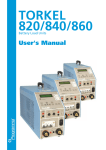
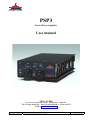
PSP3
Stereo M/S preamplifier
User manual
AETA AUDIO
361, avenue du Général de Gaulle – 92140 Clamart – FRANCE
Tél. +33 (0)1 41361212 – Fax +33 (0)1 41361213 – Telex 631178
Web : http://www.aetausa.com
55 000 020 – Ed. B
PSP3 – User manual
Ce document est la propriété d'AETA, et ne peut être reproduit ou communiqué sans autorisation
October 2002
55 000 020-B PSP3 (Engl.).doc
Table of contents
1.
Introduction....................................................................................................................... 1
2.
Connections ....................................................................................................................... 2
2.1. Microphone or line inputs ............................................................................................................ 2
2.2. Line outputs.................................................................................................................................. 2
2.3. Headphone or unbalanced line outputs (3.5 mm stereo mini-jack) .............................................. 2
2.4. External DC socket....................................................................................................................... 3
3.
Front panel controls.......................................................................................................... 4
3.1. “ON/OFF” switch......................................................................................................................... 4
3.2. Power indicator, “BAT.” .............................................................................................................. 4
3.3. Overload indicators, “OVLD”...................................................................................................... 4
3.4. Sensitivity setting, “GAIN”.......................................................................................................... 4
3.5. Selection of the microphone powering mode, “PHANTOM”...................................................... 5
3.6. High pass filter, “FILTER” .......................................................................................................... 5
3.7. Output level setting, “MASTER”................................................................................................. 5
3.8. L/R balance adjustment, “BALANCE”........................................................................................ 5
3.9. Output level setting, “PHONE”.................................................................................................... 5
3.10. “Sound image width” setting for M/S recording........................................................................ 5
3.11. “L/R - M/S” mode selector (for headphone monitoring or mini jack outputs) .......................... 6
4.
Other control elements ..................................................................................................... 7
4.1. “L/R - M/S” switch on the connector panel ................................................................................. 7
4.2. “R/S” signal phase inverter on the bottom panel.......................................................................... 7
5.
Power supply ..................................................................................................................... 8
5.1. External power supply.................................................................................................................. 8
5.2. Disposable and rechargeable batteries.......................................................................................... 8
6.
Annexes .............................................................................................................................. 9
6.1. Using L/R - M/S matrixing .......................................................................................................... 9
6.2. Product specifications (data sheet) ............................................................................................. 10
55 000 020 – Ed. B
PSP3 – User manual
Ce document est la propriété d'AETA, et ne peut être reproduit ou communiqué sans autorisation
October 2002
55 000 020-B PSP3 (Engl.).doc
1. Introduction
The PSP3 is a professional quality stereo microphone/line preamplifier; it also integrates functions
making it suitable for M/S recording.
This preamplifier features a range of sensitivity and microphone powering capabilities that is wide
enough to fit all types of professional microphones.
The PSP3 operates either from internal disposable or rechargeable batteries, or from an external DC
source.
In addition, users of M/S stereo microphones are offered the capability to tune the stereophonic image and
to monitor the signal in an appropriate mode.
With its performance and its audio correction functions (high pass filter, balance…), the PSP3 ideally
complements a portable audio recorder such as a DAT or an MD recorder.
UNPACKING AND INSPECTION
The PSP3 products are carefully checked for good condition before being shipped from the
factory. Despite the protective carton and rugged design, shipping may damage the unit.
Check for possible carton damage when unpacking the unit. Please save the carton for return
shipment if required.
AETA AUDIO does not warrant against damage caused by returning products in other
cartons than the original ones or improperly packing the products.
If shipping damage is evident, notify the transportation company immediately. Only the
consignee can file a claim with the carrier for shipping damage. AETA AUDIO will fully cooperate in such an event.
Be sure to save the carton for the shipper to inspect.
55 000 020 – Ed. B
PSP3 – User manual
Ce document est la propriété d'AETA, et ne peut être reproduit ou communiqué sans autorisation
October 2002
1
55 000 020-B PSP3 (Engl.).doc
2. Connections
All connectors are grouped on one single panel of the PSP3:
Figure 1 – PSP3 “Connector panel”
2.1. Microphone or line inputs
Transformerless symmetrical inputs; can be used with unbalanced sources.
Required plugs: Cannon axr-3.12, Neutrik nc3mx, or Switchcraft a3m.
Wiring :
•
1 – Ground or shield
•
2 – “Hot”, +
•
3 – “Cold”, - (to be connected to ground for unbalanced sources)
2.2. Line outputs
Transformerless balanced outputs; can be connected to asymmetrical loads.
Required plugs: Cannon axr-3.11, Neutrik nc3fx, or Switchcraft a3f
Wiring :
•
1 -- Ground or shield
•
2 -- “Hot”, +
•
3 -- “Cold”, - (to be connected to ground for asymmetrical loads)
2.3. Headphone or unbalanced line outputs (3.5 mm stereo mini-jack)
Unbalanced low impedance outputs (50 Ohm).
Wiring :
•
Jack Tip = + of LEFT channel
•
Jack Ring = + of RIGHT channel
•
Jack Sleeve (body) = Ground for both channels
55 000 020 – Ed. B
PSP3 – User manual
Ce document est la propriété d'AETA, et ne peut être reproduit ou communiqué sans autorisation
October 2002
2
55 000 020-B PSP3 (Engl.).doc
2.4. External DC socket
The PSP3 can be powered from an external DC power source with a 6 V to 12 V voltage (15 V
maximum), using the power socket located on the “connector panel”, near the “R” female XLR socket.
Before connecting an external source, check that its polarity is as specified on the unit: centre
pin = positive voltage, outside ring = negative voltage.
55 000 020 – Ed. B
PSP3 – User manual
Ce document est la propriété d'AETA, et ne peut être reproduit ou communiqué sans autorisation
October 2002
3
55 000 020-B PSP3 (Engl.).doc
3. Front panel controls
Figure 2 –PSP3 “control panel”
3.1. “ON/OFF” switch
Put this switch on the “OFF” position when the unit is not used.
3.2. Power indicator, “BATT.”
This indicator is normally green; it switches to red and blinks when the power voltage decreases beneath
+5 V. In such event, the batteries must be replaced for a new set, or (if operating from an external DC
source) the external DC voltage must be increased to more than +5 V.
However, immediate battery replacement is not mandatory, as the DC/DC converter inside the PSP3
maintains full performance until the power voltage reaches 3.5 V.
3.3. Overload indicators, “OVLD”
The “L” and “R” red LEDs warn the operator when the signal level is too high on the corresponding input
channel. The LED lights red when the signal reaches –3 dB below the clipping level. In such situation, it
is advisable to reduce the input sensitivity by setting the slide switch accordingly, until the LED
indicators stay permanently off.
3.4. Sensitivity setting, “GAIN”
Select the appropriate sensitivity depending on the type of microphone and/or source:
•
“70dB” position: suitable for dynamic or ribbon microphones, also for static or electret
microphones when used far from the sound source.
•
“40dB” position : suitable for high output level static or electret microphones when used at
average distance from the sound source.
•
“20dB /LINE” position : suitable for static or electret microphones used at close distance from the
sound source, or for external devices with line level outputs (such as e.g. CD players, DAT
recorders, etc.).
55 000 020 – Ed. B
PSP3 – User manual
Ce document est la propriété d'AETA, et ne peut être reproduit ou communiqué sans autorisation
October 2002
4
55 000 020-B PSP3 (Engl.).doc
3.5. Selection of the microphone powering mode, “PHANTOM”
The “PHANTOM” 3-position slide switch allows selecting the powering mode used for the microphones
or sources connected to the PSP3:
•
48V : for powering static or electret microphones using 48 V phantom supply.
•
------- : for dynamic or ribbon low sensitivity microphones; to be used also for line level (-20dBu
to +18dBu) balanced or unbalanced inputs.
•
12V : for powering static or electret microphones using 12 V phantom supply.
3.6. High pass filter, “FILTER”
This filter can be used for eliminating undesirable low or very low frequency noise, like is often
encountered on field recordings (microphone handling noise, wind noise, engine or exhaust pipe noise,
ground vibrations, etc.).
A –12dB/octave filter can be inserted on both L and R channels by setting the “Filter” slide switch to the
desired position: “Off” (full bandwidth), 80Hz or 120Hz cut-off frequency.
3.7. Output level setting, “MASTER”
The centre knob of the Master/Balance coaxial potentiometer is used for adjusting the level of the
balanced L and R outputs (XLR male sockets); this setting also influences the maximum level on the
“Phone” outputs on the 3.5 mm stereo mini-jack.
3.8. L/R balance adjustment, “BALANCE”
The outside ring of the Master/Balance coaxial potentiometer is used for balancing the level between the
L and R sources. Up to 16 dB compensation (6:1 ratio) is available, as the level on each channel can be
shifted by –4 dB to +12 dB.
Correcting for a possible level mismatch is even more important when recording in M/S mode, as most
often a bi-directional transducer is used for the “Side” signal while a much more sensitive cardioid
microphone produces the “Mid” signal.
3.9. Output level setting, “PHONE”
The centre knob of the “Phone / M/S” coaxial potentiometer is used for adjusting the level of the
unbalanced L and R outputs on the 3.5 mm stereo mini-jack. These outputs can be used either for
connecting a stereo headphone, or for driving the stereo input of a recorder (or other device) not fitted
with XLR symmetrical inputs.
Remember this is a “post master” setting which comes after the “Master” stage, so the output level also
depends on the Master potentiometer setting.
3.10. “Sound image width” setting for M/S recording
The outside ring of the “Phone / M/S” coaxial potentiometer is used for continuously adjusting the
“stereo width”, from a pure mono image (on “M” position) to an artificially extended stereo image (on
“S” position). The centre position (with detent) yields a “normalised” 110° angle.
This setting comes in addition to the previously described sensitivity balance adjustment.
55 000 020 – Ed. B
PSP3 – User manual
Ce document est la propriété d'AETA, et ne peut être reproduit ou communiqué sans autorisation
October 2002
5
55 000 020-B PSP3 (Engl.).doc
3.11. “L/R - M/S” mode selector (for headphone monitoring or mini jack
outputs)
When set in “M/S” position, this switch inserts an M/S - L/R encoder/decoder on the path to the stereo
mini-jack, so allowing the monitoring in conventional stereo mode while recording in M/S mode. For
normal stereo recording, leave this switch in its “L/R” position.
55 000 020 – Ed. B
PSP3 – User manual
Ce document est la propriété d'AETA, et ne peut être reproduit ou communiqué sans autorisation
October 2002
6
55 000 020-B PSP3 (Engl.).doc
4. Other control elements
4.1. “L/R - M/S” switch on the connector panel
This switch is purposely difficult to access; it optionally inserts an M/S - L/R encoder/decoder on the path
to the balanced outputs (male XLR sockets):
•
In the “L/R” position, no matrixing takes place on the input signals; it is then possible to record
either a conventional stereo signal, or to record “M/S” sources “as they are” (however, it is
possible on a later stage to adjust the stereo image, using the PSP3 at playback time for inserting
the M/S-L/R decoder and adjusting the above described image width setting).
•
In the “M/S” position, the “M/S” signal is decoded and converted to conventional L/R stereo; the
image width can be adjusted from mono to “super-stereo” using (as described previously) the
outside ring of the “Phone / M/S” coaxial potentiometer.
4.2. “R/S” signal phase inverter on the bottom panel
The “R/S” signal phase inverter, located on the bottom panel of the PSP3, enables to invert the phase of
the signal on the “R” input (which corresponds to “S” signal when using an M/S stereo microphone
couple). Inverting the “S” signal phase exchanges the L and R channels (inverted stereo), after decoding
by the “M/S – L/R” matrix in the PSP3.
As an example, if an M/S microphone couple is mounted on a boom, the phase inverter may be used for
recovering the same proper L and R “positions” in both cases when the microphones are above or beneath
the boom.
55 000 020 – Ed. B
PSP3 – User manual
Ce document est la propriété d'AETA, et ne peut être reproduit ou communiqué sans autorisation
October 2002
7
55 000 020-B PSP3 (Engl.).doc
5. Power supply
5.1. External power supply
Do not use small cheap AC adapters; these can be a source of noise and failures.
For powering the PSP3, a filtered and regulated DC source is required, capable to supply up to 500 mA.
Its voltage should be in the 6 V to 12 V range (NOT MORE THAN 15 V).
The PSP3 automatically switches between the batteries and the external supply, with no noise or drop-out.
The external supply has a priority over the batteries as long as its voltage overcomes that of the 6 batteries
in series.
Before connecting a power source, check that its polarity is compliant with that specified on the PSP3
(see above 2.4, External DC socket, p. 3).
CAUTION : The negative pole of the PSP3 power supply is connected to its metal case. If
powering the unit from the battery of a vehicle with “+” connected to the vehicle chassis,
especially keep the PSP3 and linked devices isolated from the vehicle chassis, and always
unplug the power cable when not using the PSP3.
5.2. Disposable and rechargeable batteries
To get the best results and autonomy from the PSP3, it is required to use only alkaline AA-type batteries;
the batteries must be new or recent and homogenous.
•
Never mix new and used batteries in the battery compartment.
•
Never leave used batteries in the device after use.
THE ABOVE IS ESPECIALLY IMPORTANT WHEN THE WEATHER IS HOT OR VERY WET.
5.2.1. Ni-Cd or Ni-MH rechargeable batteries
As an alternate source, using such batteries is more economic, at the cost of a lower autonomy.
The batteries must be removed from the PSP3 for recharging.
5.2.2. Low-cost disposable batteries
Using such batteries is highly questionable, as they may leak and cause major damage to the device.
Moreover, very low autonomy can be expected from such batteries (at most 20% that of alkaline
batteries).
If such batteries have to be used for emergency, remove them from the device just after use or as soon as
the “BAT” battery indicator goes red.
The warranty does not cover damage induced by using such type of batteries.
55 000 020 – Ed. B
PSP3 – User manual
Ce document est la propriété d'AETA, et ne peut être reproduit ou communiqué sans autorisation
October 2002
8
55 000 020-B PSP3 (Engl.).doc
6. Annexes
6.1. Using L/R - M/S matrixing
This chapter shows examples of situations where L/R↔M/S matrixing can be used and the effect of
matrixing in these situations.
6.1.1. Case 1: standard stereo engineering
This is the most common application. In this case, mono microphones or normal (L/R) stereo microphone
couples are used, and the output of the PSP3 is in standard stereo format.
L/R↔M/S matrixing is not needed in such an operating mode.
6.1.2. Case 2: stereo recording using MS microphones
In this case, M/S stereo microphone couples are used, and the output of the PSP3 is in standard stereo
format.
Instead of left and right, the mixer buses actually process M (Mid) and S (Side) signals. In order to output
normal stereo signals, L/R↔M/S matrixing must be applied at the output (switch of the connector panel
on the “M/S” position). Matrixing is also needed for monitoring a normal stereo signal on the headphones
(front panel switch on the “M/S” position).
55 000 020 – Ed. B
PSP3 – User manual
Ce document est la propriété d'AETA, et ne peut être reproduit ou communiqué sans autorisation
October 2002
9
55 000 020-B PSP3 (Engl.).doc
6.1.3. Case 3: MS recording using MS microphones
In this case, M/S stereo microphone couples are used, and the output is kept in M/S format for recording.
In this way, further stereo image processing is made possible with studio equipment in later production.
The PSP3 channels process M (Mid) and S (Side) signals. L/R↔M/S matrixing is not applied at the
output (switch kept on the “L/R” position). However, matrixing is needed for monitoring a normal stereo
signal on the headphones (front panel switch on the “M/S” position). The stereo image width setting can
be used for changing the stereo image.
6.1.4. Case 4: MS recording using classical microphones
In this case, mono microphones or normal (L/R) stereo microphone couples are used, but the output is
encoded in M/S format for recording. In this way, further stereo image processing is made possible with
studio equipment in later production.
In order to encode the outputs in M/S format, L/R↔M/S matrixing is applied at the MAIN output
(connector panel switch on the “M/S” position).
6.2. Product specifications (data sheet)
The characteristics and performance of the product are detailed in the attached data sheet.
55 000 020 – Ed. B
PSP3 – User manual
Ce document est la propriété d'AETA, et ne peut être reproduit ou communiqué sans autorisation
October 2002
10
55 000 020-B PSP3 (Engl.).doc